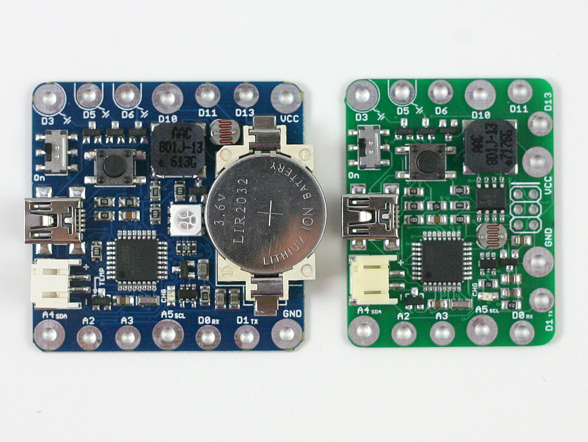
Liked how SquareWear 2.0 has so many built-in components and yet so compact in size? Introducing SquareWear Mini — the little sister of SquareWear that has the same capabilities (and more!) but is 25% smaler in size!

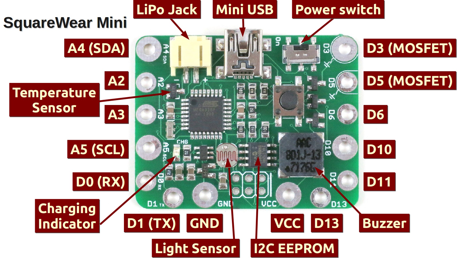
SquareWear Mini
Available for purchase at Rayshobby Shop.
So what is SquareWear Mini? Similar to SquareWear 2.0, the SquareWear Mini is essentially an Arduino running at 3.3V and 12MHz. It is based on the ATmega328 microcontroller, and it has a load of build-in components, including USB port, power switch, pushbutton, buzzer, temperature sensor, light sensor, MOSFETs, lithium battery jack, and lithium battery charger. The pins have enlarged sizes for sewing with conductive threads, for soldering sew-on snaps, and they are great for touch sensing too.
How did I shrink it to be smaller than the original SquareWear? Well, by removing the on-board rechargable coin battery and color LED, and routing some pins to the side. With the space saved, I was even able to add a 16KB I2C EEPROM for storing extra data. Shortly you will see how this is useful. These changes were made because SquareWear designed specially to be attached to a chainable color LED matrix. This will enable a whole new set of exciting projects, as you can see from the video above.
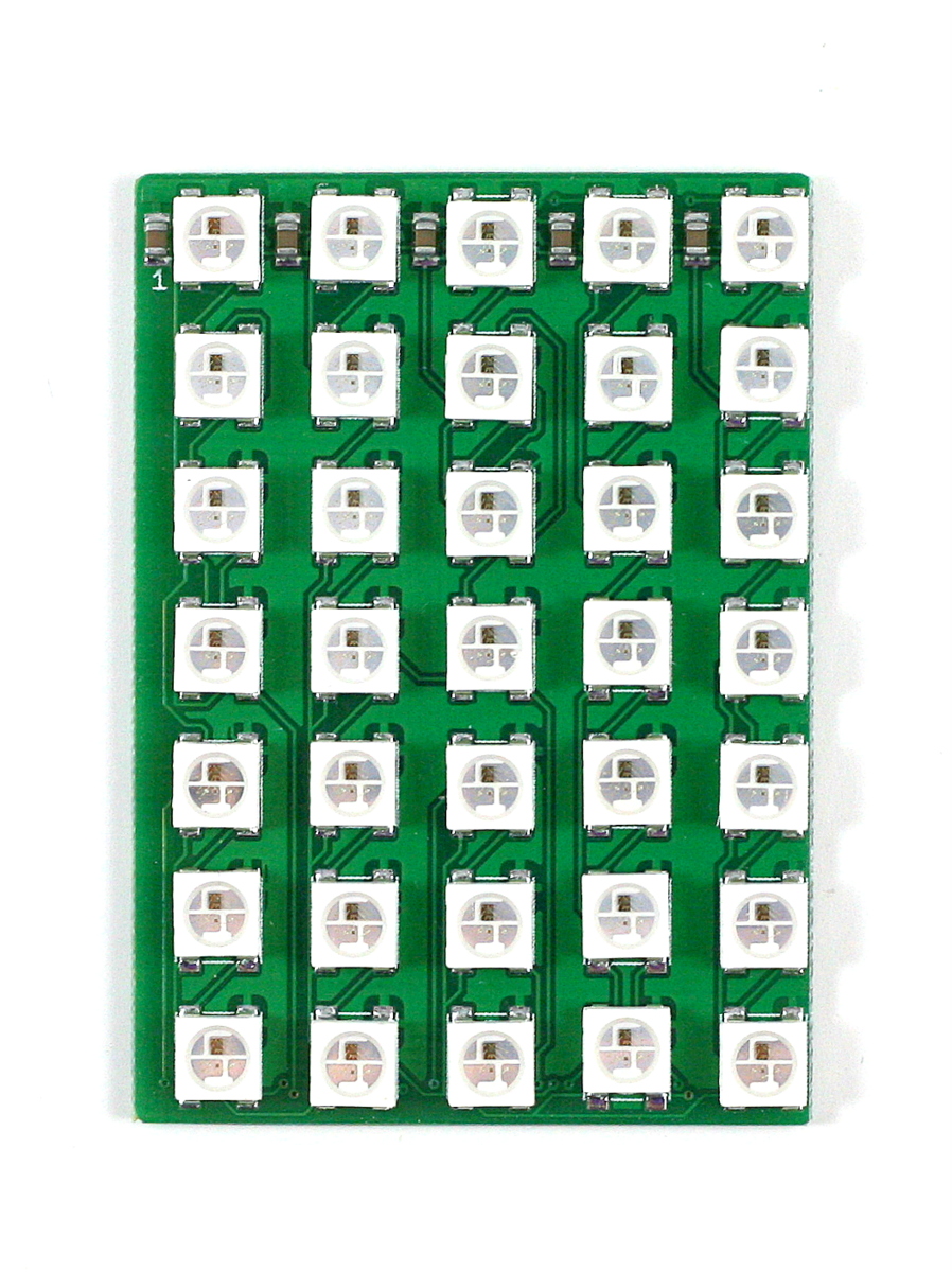
Color LED Matrix
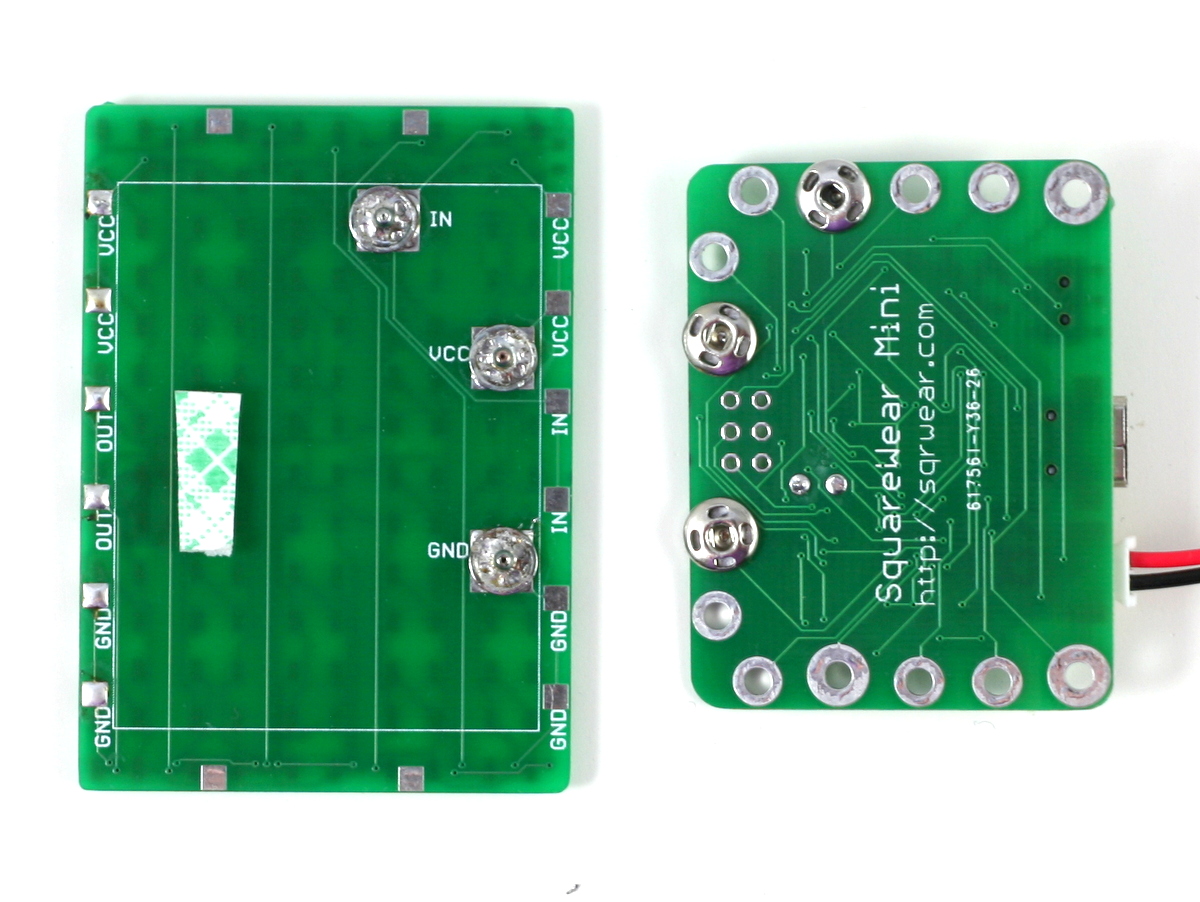
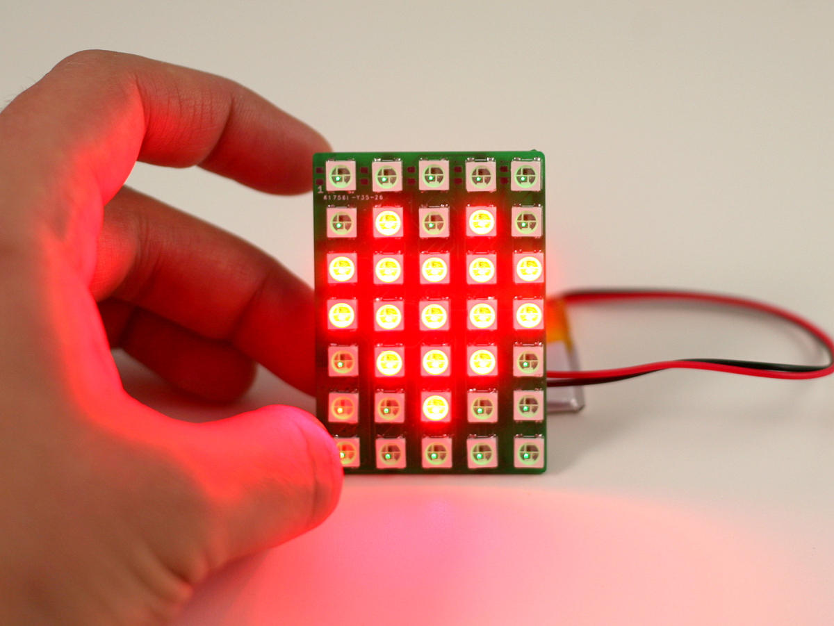
So let me briefly explain the LED matrix. Each matrix contains 35 LEDs arranged on a 5×7 grid with 8mm spacing. It uses the WS2812B color LEDs. These are great because the LED has a built-in chip that allows you to daisey chain them in bulk and still be able to individually set the color of any LED with only one microcontorller pin. Adafruit gave them a name calle the Neopixels. No matter how many LEDs you have, you only need 3 pins to get them to work, namely the VCC, GND, and DATA_IN pins.
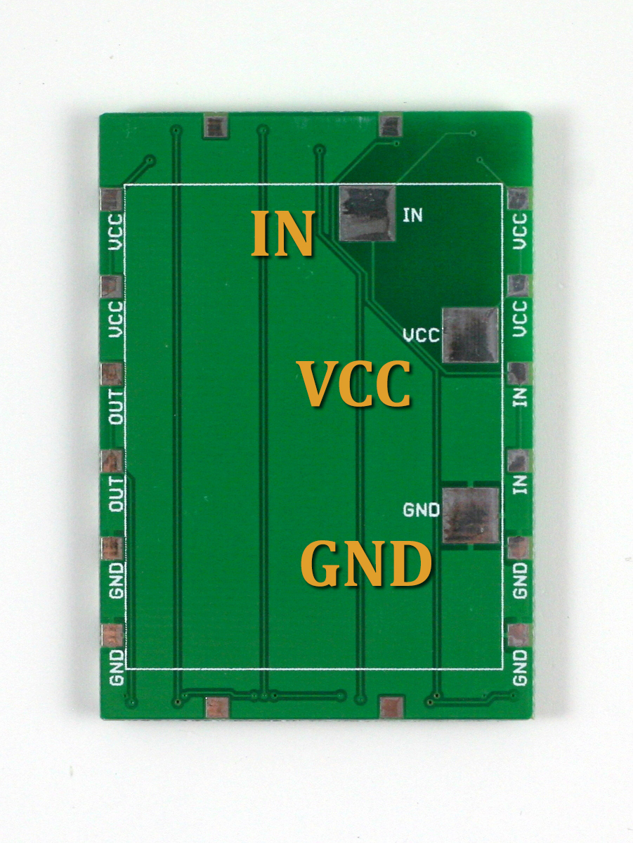
These pins are mapped out at the back of the LED matrix. The locations of these pins exactly match the VCC, GND, and digital D10 pins on SquareWear Mini, so you can easily attach SquareWear Mini with the LED matrix by either soldering some sew-on snaps, or directly soldering the two boards together.

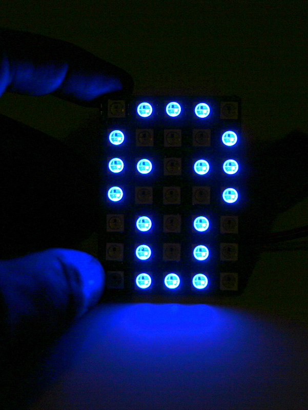
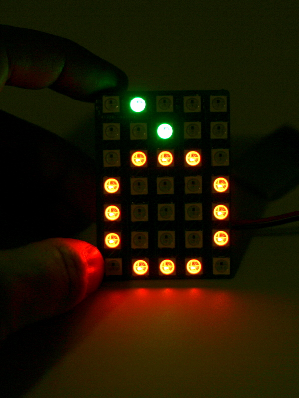
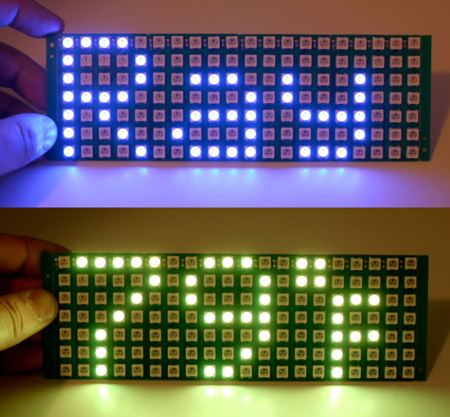
The resolution 5×7 is not a whole lot, but it is sufficient to display ASCII characters and a lot of cute icons:

The LED matrix is designed to be chainable too. Each board has DATAIND pins on one side, and DATAOUT on the other side. To extend the number of boards in the X direction, just place two matrices side by side and solder across the 6 pins on the boundary. The solder will get the two boards firmly attached to each other. Chain several boards together to make a large display panel, and it’s great for showing text and messages in any color you want. For example, you can use it as a name tag, or a thermometer (remember, SquareWear Mini has a built-in temperature sensor!)
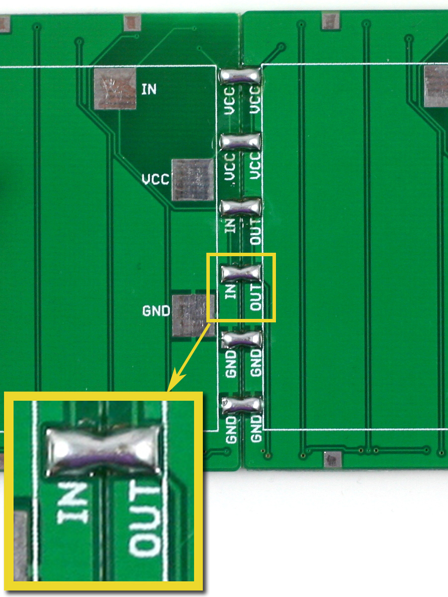
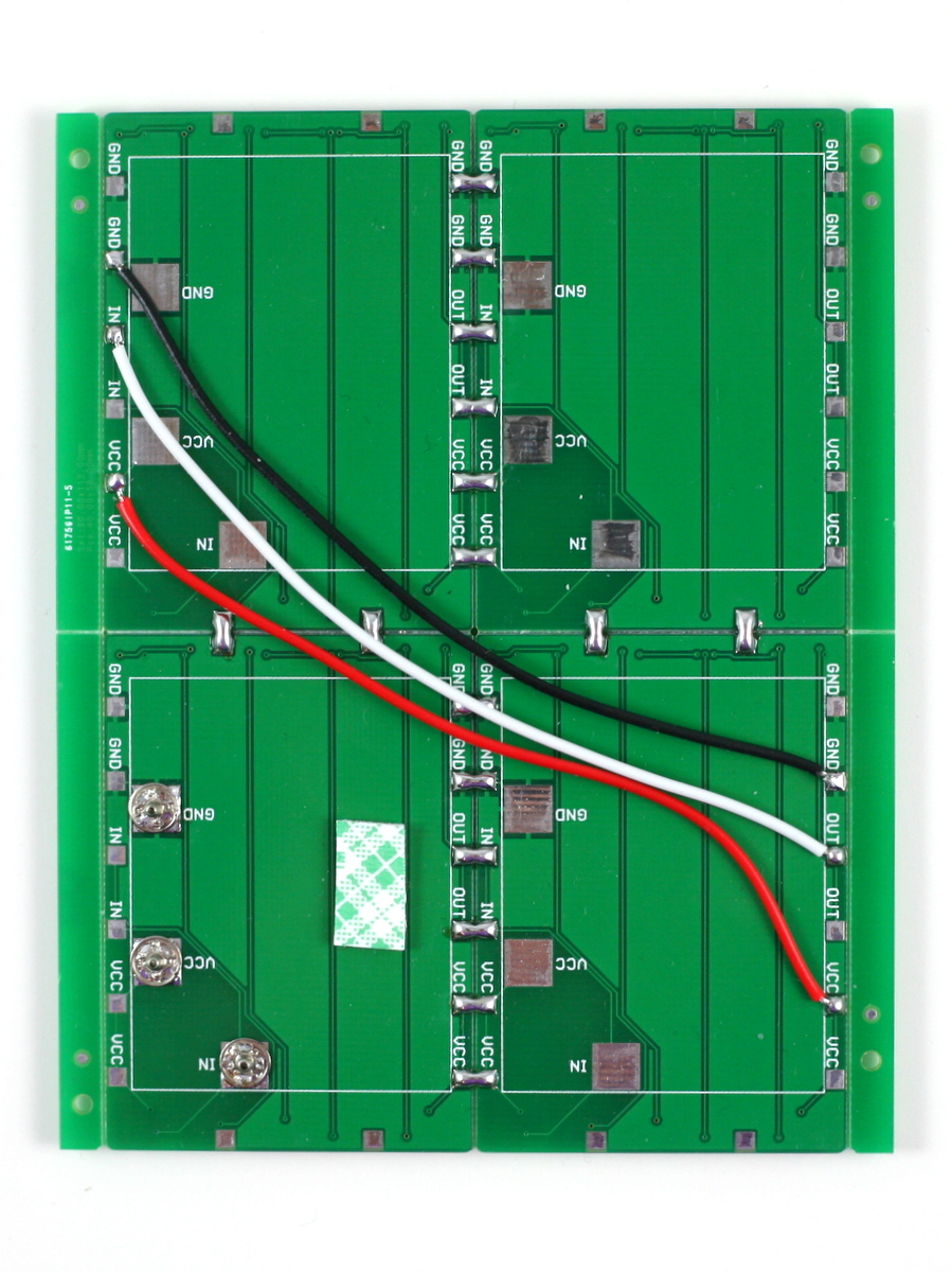
You can also extend the panel in the Y direction. To do so, use three wires to connect the VCC, GND, and DATA_OUT pins of the previous row to the VCC, GND, DATA_IN pins of the next row. Also solder across the pins on the vertical direction to firmly attach the two rows of boards together. There you go, a bigger panel to display more detailed graphics!

Software Demos
We’ve re-worked the SquareWear software library to include LED matrix demos. These demos work on both the original SquareWear 2.0 and SquareWear Mini. Check the video above for selected examples. The demos are included in the pre-configured software package, and are also available for downloaded individually at the SquareWear Github repository.
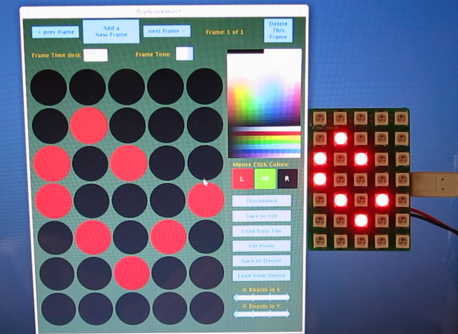
What I want to highlight here is the Flipbook Animation demo. It’s a great demo that allows you to interactively design pixel patterns and even an animation. SquareWear Mini can store the frame data into the I2C EEPROM and play it back later. Even better, it comes with sounds too! So how does this work? First, you upload the Flipbook Arduino code to SquareWear. Then, run the Flipbook host software. The host software is written in Processing and is cross-platform. It uses the HID Serial interface to communicate with SquareWear. In the host software you can click on pixels and assign them color values. These values are immediately transferred to SquareWear so you can preview the frame in real-time. For each frame you can specify the frame time and optionally a music note to play. You can create multiple frames, navigate through each frame, make modifications, save the animation to a disk file etc. At last, when you are satisfied with it, click on ‘Transfer to Device’ and the data will be stored into EEPROM. Next time you turn on SquareWear, just click the pushbutton and it will play back the stored animation. Isn’t that cool? With this tool, you never have to think about converting pixel patterns to programming code any more. Let your creativity and imagination take over!

Hope you like SquareWear Mini, and let us know your cool project ideas!
