Feed on
Posts
Comments

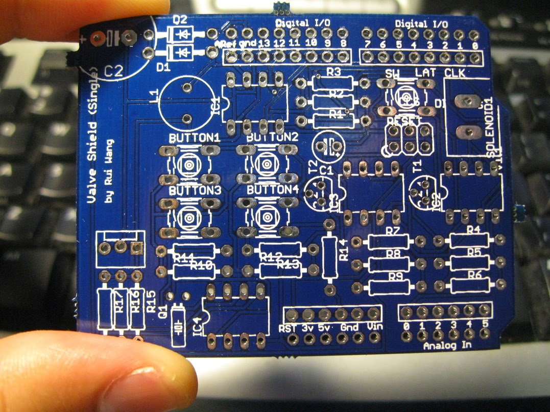
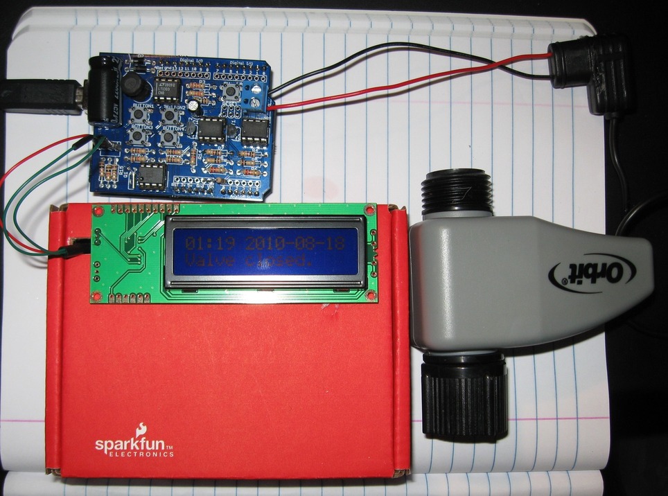
After finishing the previous minty water valve controller, I decided to make it an Arduino shield. This way, I can easily stack it onto other shields and extend its capability. I also added a few input buttons, and a DS1337 real-time clock, so that it can keep up with accurate time. Now the circuit has become much smaller, so I can’t produce it with home-made PCB any more(sadly…). Instead, I ordered professionally made PCBs from Laen, and here you are, meet the Arduino WaterValveShield!

PCB board:

Components soldered:

Close-up view:

Connected to a serial LCD display

The schematic:

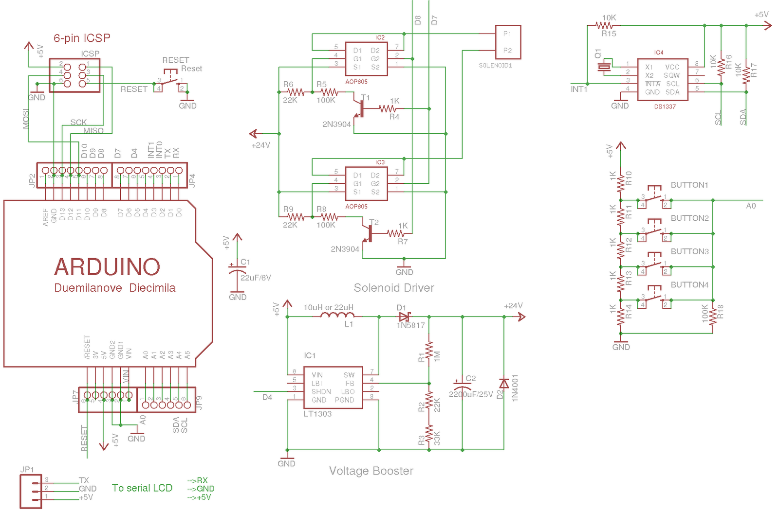
You can download Eagle schematic and PCB design here. Feel free to use it and/or modify it, but be kind to give me some credit for it 🙂

Parts list with Mouser/Digi-key links: valve_shield_parts.zip 

As for sketch code, refer to my previous posts for code to control the valve and read input buttons. To interface with DS1337 RTC, I use this excellent RTC library.

Next steps:

8 Responses to “Meet the Arduino WaterValveShield”

  1. Laen says:

    This looks like it would match really well with the Draculino, a micropower Arduino variant.

  2. Rik says:

    Ray — Great work. This is needed as many people want to have more ability to get away from the standard timer units that come with these units. One question, I have used 24 volt DC power supply and gravity flow out of a tank and can not get the value to open. Have you played with how much water pressure is needed to get the value to open? I would like to use this type setup in an aquaponics situation with only a sump pump sending water back into the fish tank that is above my grow beds.

    Thanks,

    Rik Kretzinger

  3. Ray says:

    To Laen, yes, a low-power Arduino variant is exactly what I am looking for. Thanks for letting me know.

  4. Ray says:

    Rik, there is probably a minimum water pressure required to open the valve. It should be on the product box which I've thrown away. Have you considered using a small water pump such as mentioned in this Garduino project: http://garduino.dirtnail.com/

  5. plumbing says:

    It is a great option to have a different timer and switch from standard units which are very common. This is needed to get away from what is common as many people have the ability to do it.

  6. pex plumbing says:

    I fully agree with you its very important!

  7. Chris says:

    Could this be modified to work at 12 Volts for Orbit’s 13V Latching Solenoid? I found them at both Lowe’s and Home Depot. http://www.orbitonline.com/lib/media/57861-03%20rA(5)1.pdf is the most Info I found on them but testing one I picked up seems to work fine on 12 volts from a computer power supply. Current flowing one way opens it and the other closes it.

    • ray says:

      Yes, to change from 24V to 12V is just a matter of changing a resistor value. But I believe I have the same solenoid as you have, so this exact circuit should work on yours too. Note that since the circuit uses capacitative charge, even though it’s at 24V initially, it won’t damage your solenoid because the capacitor only has a limited amount of charge and the voltage will drop instantly as it dumps the charge to the solenoid. This is different from using your computer supply, which provides persistent 12V, so a prolonged connection may end up damaging the solenoid.

Leave a Reply