Getting Started
Warning: battery quality and condition vary. Severe discharging may cause some batteries to leak and/or become hot. In case such problems occur, please remove the battery from AASaver immediately. We are not responsible for damage caused by leaking battery.
v2.1
Please follow the AASaver 2.1 User Manual for assembly and usage instructions.
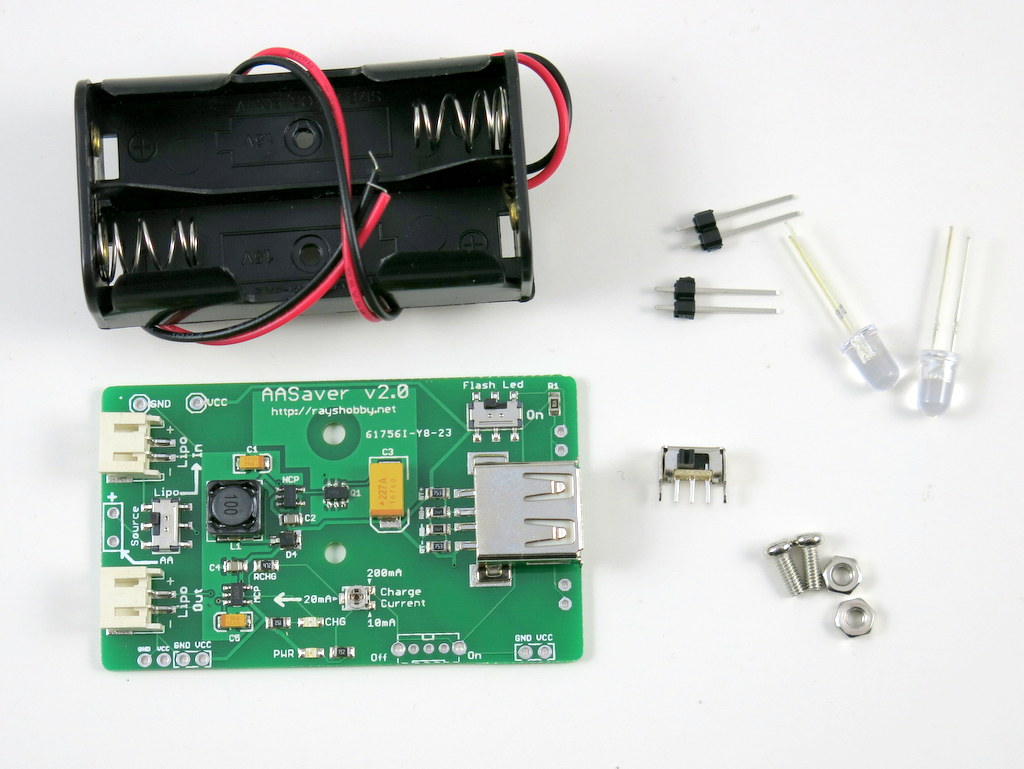
v2.0
Please follow this blog post for assembly and usage instructions.
v1.1
The kit includes a pre-soldered circuit board. To start using it, follow the steps below:
- Insert the four battery clips into the PCB holes, and then insert two AA batteries by following the directions marked on the PCB silkscreen.
- Turn the power switch to ‘on’. The on-board indicator LED should light up. If not, check if you have inserted the batteries in the wrong direction.
- Use the voltage switch to select output voltage: 5V or 3.3V.

Note:: v1.1 has an on-board 39ohm SMD resistor, so no through-hole resistors are needed. In addition, both flash LEDs are moved to the left side so they point to the same direction. A separate LED switch is also added so that it can be used simultaneously as breadboard power supply and LED flashlights. Other than these changes, the rest of the instructions are the same with v1.0 below.
v1.0 (Nov 2011)

LED Flashlight


To use the AASaver as an LED flashlight, you should solder the two LEDs and 68 ohm resistors onto the PCB. Pay attention to the polarity of the LED — the longer lead should go into the slot marked by ‘+’. You can decide the height of the LED. You can also solder just one LED, and bend it 90 degrees so that it faces forward. This makes it a bit more comfortable to hold in hand:

LED Brightness. The two LEDs are white-colored with built-in focusing lens. The luminous intensity is rated at 25000 mcd, which is pretty bright. Note that the voltage switch can control the LED brightness: 5V makes them brighter and correspondingly draws more current.
Breadboard Power Supply


To use the AASaver as a breadboard power supply, just solder the two pin headers onto PCB. The spacing between them fits a standard breadboard. To plug it into the breadboard, watch the polarity: make sure the Vcc and Gnd marks on the PCB matches your breadboard polarity. The output voltage can be either 5V or 3.3V, using the voltage selection switch.
Current Output. The maximum output current depends on the condition of the batteries as well as the output voltage. With a pair of fresh batteries, it can output at least 300mA at both voltage levels. Even with old batteries that have been significantly used, it can usually still output a sustained current of 50-100mA @ 5V (and higher at 3.3V), which is sufficient for many breadboard experiments.
Use a Single AA Battery
To use a single battery instead of two, just solder a wire between the two outer pins of the bottom battery clips. See the example below. The output voltage remains roughly the same, since it’s regulated. The maximum output current, however, will reduce roughly by half.


Use AAA Batteries
To use AAA batteries, since they are smaller, you need to fill the gap between the battery and the clip. The easiest way is to insert a folded piece of aluminum foil, as shown in the picture below.
