Recently I was fortunate to receive a Microchip PICkit 2 from Newark.com to write a review on. I was very excited to get it because I have always wanted to learn about PIC microcontrollers. Why? Well, so far I have been quite experienced with Atmel’s AVR family chips, thanks to the Arduino that first got me into electronics. But it’s time to try something new in a new year 🙂 PICs offer several nice appeals including their product variety and functionality (e.g. support for USB, Ethernet, touch sensing etc.) and they have very competitive pricing. I know there are tons of debates about AVRs vs. PICs online. For now I am going to put them aside and make my own comparisons later after I get a good grip of both.
First Impression
PICkit 2 is a very popular tool for programming and debugging Microchip’s PIC microcontrollers. If you want to learn PIC programming, you almost certainly should get one. With the latest device file, it can support most PICs available on the market (although for some of the newer ones it only supports programming and not debugging). Microchip has an updated version — PICkit 3 which supports everything, but I prefer PICkit 2 because it’s cheaper ($34.99) and provides everything I need.
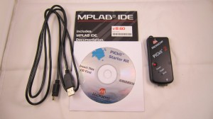
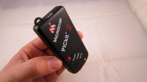
The package (product no. PG164120) contains the programmer itself, two CDs, and a USB cable. The programmer looks very compact. It has a USB port (as well as a key ring) on the top, a red button and three LEDs (power, target, and busy) on the front, and the 6-pin ICSP (In-Circuit Serial Programming) port on the bottom.
 |
 |
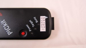
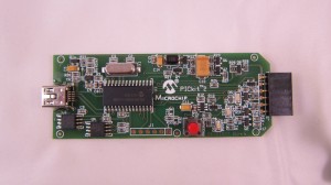
Since I am new to the ICSP pins and can easily get myself confused with the AVR’s ISP pins, I made a small label with all the pin names and attached it to the programmer. This way I will never forget the pins when prototyping circuits! The 6 pins are: Vpp, Vdd, Vss, ICSP-Data, ICSP-Clock, and the last pin is unused. Among them, Vpp can provide +12v for high-voltage programming, and Vdd/Vss can supply 5V or 3.3V to power your circuit, which is very convenient. The picture on the right below shows the circuit inside the programmer. It is based on a PIC18F2550 MCU.
 |
|
At this point I have to say that I like this programmer much better than AVR’s comparable programmer at the same price. Why?
- I like how the ICSP pins are all on one line. This makes it easy for breadboard experiments as it only needs a 1×6 pin header. In comparison, AVR’s ISP programmer requires a 2×3 pin header, which is always a pain for setting up on breadboard.
- It can do high-voltage programming, which means if I somehow messed up with the fuse settings I don’t have to panic. In comparison, AVR’s ISP programmer doesn’t do this (unless if you get a more expensive model). I remember the horrible experience when I first programmed my ATMega328 with wrong fuse values, I had to spend a whole day searching for solutions. Eventually I made a high-voltage rescue circuit and fixed the problem. But what a pain!
- It can provide power (anywhere from 2.5V to 5V) to your circuit.
- Probably the most valuable of all: it is a programmer and a debugger. You can use it for in-circuit debugging too! How nice! For AVRs, the comparable product would be quite a bit more expensive.
So overall, I am really glad to find out that this small and inexpensive programmer packs a lot of nice features in it.
Software Setup
Next I will try to write my first PIC program. There are basically two pieces of software to install: the MPLAB (version 8.6) which is the programming IDE, and the PICkit 2 standalone program (version 2.61). They are in the attached CDs, but you can also download them online at Microchip’s product website.
The MPLAB integrates everything you need: programming environment, compiler, uploader, and debugger. However, it turns out that it won’t support some of the newer chips (such as the one I got) if you are using PICkit 2. That means you can compile the program but won’t be able to upload it to the chip. The upgraded version PICkit 3 can handle all chips, but I don’t have it! Fortunately, PICkit 2 has a standalone program to work with the newer chips. Be sure to download the latest Device File from that website.
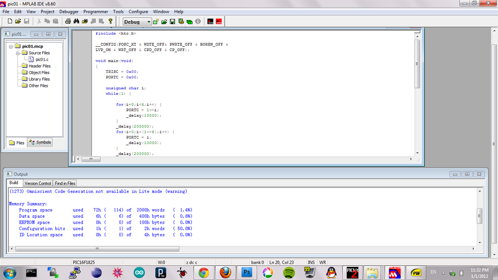
To write a program, you can either use assembly language or use C. I am going with C since I don’t know how to accomplish even a relatively simple program in assembly language. It makes my head blow… Anyway, MPLAB comes with a free HI-TECH C compiler (PICC light version). You can follow the ‘Quick Start’ tutorial, available in the compiler’s installation folder to easily write your first ‘Hello World’ (i.e. flashing LED) program. Here is a snapshot of mine:
The ‘Config’ bits are a bit confusing to me at first. But a read of the microcontroller’s datasheet will make everything clear. These are similar to the fuse settings in the AVRs. The main difference is that here you write the bit settings directly in the program, whereas AVRs separate the program with the fuse settings.
“Hello World” Experiment
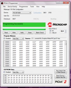
For my first experiment, I picked the PIC16F1825 microcontroller. It has 14KB program flash, 1KB RAM, 256B EEPROM, USART, 12 I/O pins, and it costs only $1.50. I thought I made a good choice. Unfortunately soon I found a small issue, which is MPLAB does not fully support this microcontroller if you are using PICkit 2. You can still write and compile a program, but you can’t upload or debug the program (these are only available with PICkit 3). Fortunately, the PICkit 2 standalone program can still work with it. So the solution is to write and compile the program in MPLAB, and use the standalone program to upload:
 |
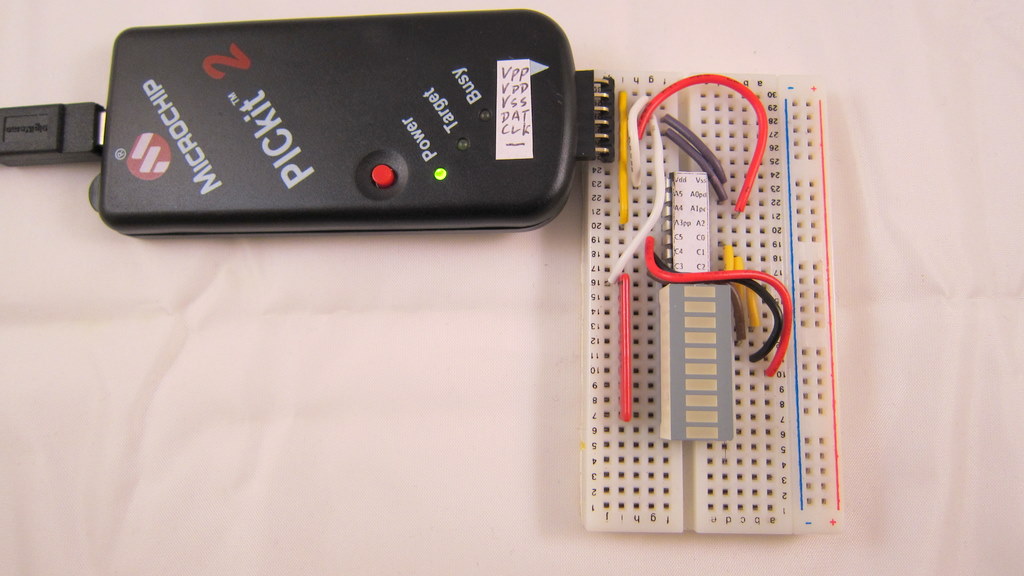 |
I made a simple testing circuit, consisting of the microcontroller, a 1×6 ICSP pin header, an LED bar graph and a resistor network. The goal is to, as we always do, flash some LEDs 🙂 The circuit is very easy to implement on a breadboard (see photo above). I basically started by connecting the 6 relevant pins to the ICSP pin header, then all port C pins (C0 through C5) to the LED bar graph, and finally the resistor network. Note that I also attached pin name labels to the microcontroller. In addition to the standard pin names (like A0, A1, C0, C1…), I especially marked the ICSP pins (VPP, ICSP-DAT, and ICSP-CLK). This makes it really easy to connect wires without having to look back again and again at the datasheet.
Upload a program: This is straightforward. First compile the program in MPLAB, then switch to the standalone program, import the compiled HEX file, and click on ‘Write’. The LEDs on the programmer will flash and after a few seconds it’s done.
Power the circuit: As I said earlier, the programmer can supply VDD anywhere between +2.5V to +5V. Note the checkbox for VDD ‘On’ and the voltage input box in the GUI above. Once you enable VDD, the Target LED on the programmer will light up, and the circuit will immediately start running. Voila, my ‘Hello World’ experiment is now complete!
Programming in Linux
I’ve also tried using the programmer in Linux (Ubuntu 11.04). First, MPLAB software installs and works just fine with Wine. Other than the GUI being a bit ugly, the software seems to be fully functional. Second, there is a tool called PK2CMD from Microchip website that works with PICkit2. You can use it to upload a compiled program to your microcontroller. Probably the only missing feature is debugging — there doesn’t seem to be a way to enable debugging in Linux. Well, you can always using MPLAB’s simulator to do software-based debugging. But if you definitely need hardware-based debugging, you can install Windows as a virtual OS in Linux. This way, all features of PICkit2 will be enabled.
Conclusion
So far my first experience with the PICkit 2 programmer has been very positive. It’s small, inexpensive, feature-rich, and relatively easy to use. I highly recommend it. In fact, if you are planning to learn PIC programming, I suggest getting this kit soon. Why? I’ve read from online websites that Microchip is discontinuing this product in favor of the newer PICkit 3, which is pricier and has actually received some negative comments (search for David Jones EEVblog PICkit 3 and you will find out). So before PICkit 2 runs out, go and grab one for yourself!
Resource Links
- Product page of PICkit 2 on Newark.com (Newark is the trade name of Farnell in the US, or Element14 in Asia Pacific).
- Microchip’s MPLAB IDE and PICkit 2 software.
- HI-TECH C compiler for PIC10/12/16 MCUs and PIC18 MCUs (the lite versions are all free).
- Alternatively, MPLAB C compilers for PIC18 or PIC24 series MCUs.
Finally, there are a few things I am yet to try, and I have put them on my todo list:
- Try the debugging feature.
- Program USB — I’ve already got a PIC that has built-in USB support. There are many PICs that have built-in USB and are in DIP package, great for breadboard prototyping.
- Try USB bootloader.
