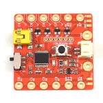
SquareWear 1.1 User Manual — Learning from Examples
Content:
- Overview
- Blinking LEDs and Digital Output
- Buttons and Digital Input
- Fading LEDs and PWM Output
- USB Serial Communication
- Analog Input
- External Interrupts
- USART and EEPROM
- I2C and Flash Read/Write
- Pulse Sensor
- Temperature Sensor
- Microchip Application Library Examples
Overview
SquareWear v1.1 is based on Microchip’s PIC18F14K50 microcontroller running at 12MHz. It has 16KB program space, 768B RAM, and 256B EEPROM. The software program is compiled in MPLAB X IDE with C18 compiler. The SquareWear library builds upon C18’s peripheral library, which comes with the installation of C18 compiler.
The SquareWear Demo Programs provide 20+ examples, which demonstrate the use of digital, analog, PWM pin functions, interrupts, reading sensors, USB serial communication, and other functions. Use them as a starting point to learn the basics of programming SquareWear.
SquareWear programs are written in the C programming language. The basic structure is as follows:
#include "SquareWear.h"
// global variables
// and user functions
int main() {
    initSquareWear();
    // ... ...
}
Note the include file at the top and the call to initSquareWear() function at the first line of the main function.
Additional Resource:
Credits: Diagrams on this page are created using Fritzing parts.
Blinking LEDs and Digital Output
Blinking LEDs is the Hello World! example of electronic projects. Blinking means you turn on and off an LED at regular intervals. SquareWear has a built-in LED connected to digital pinC7. By sending a logic high or low to pinC7 you can turn on or off the built-in LED. Here is the 01.BLINK demo program (delaytime = 500):
void main(void) {
    initSquareWear();       // must call initialization function first
    setModeOutput(pinC7);   // set pinC7 as digital OUTPUT pin
    while(1) {
        latC7 = !latC7 ;    // toggle pin C7 value
        delayMilliseconds(delaytime);
    }
}
This blinks the LED at 1Hz (0.5 seconds on, 0.5 seconds off). The second line of the main function sets up pinC7 as digital output. Then the program enter an an infinite while loop, which toggles the value at pinC7. Note that the pin alias latC7 is used to perform direct read-modify-write operations. The line latC7 = !latC7 is equivalent to setValue(pinC7, 1-getValue(pinC7)). But the former is faster as it toggles pins directly with little overhead.
One drawback of the program is that it spends most of the time doing delays. This is quite a waste of computation. Instead of use the delay function, you can use SquareWear’s timing function to track the amount of time elapsed since the last toggle. This way, you can split the computation for other tasks. Here is the 02.BLINK_NODELAY program:
void main(void) {
    ulong prev;
    initSquareWear();
    setModeOutput(pinC7);
    prev = millis();
    while(1) {
        if (millis() >= (prev+delaytime)) {    // if delaytime has passed
            prev = millis();
            latC7 = !latC7;                    // toggle pinC7
        }
    }
}
Note that it calls the millis() function which returns the milliseconds passed since the beginning of the program. The program toggles the LED only if the current time is more than 0.5 seconds past the last toggle. So the inner loop can get a share of time to perform other tasks, while the LED still blinks roughly at 1Hz frequency.
Of course this is still not very efficient, because the mcu spends a lot of time doing time checking. A more efficient way is to use the timer interrupt function which triggers and executes a callback function at regular intervals. This way the mcu can spend most of its time doing other tasks, while occasionally getting interrupted to toggle the LED. Here is the main structure of the 13.TIMER_INTERRUPT demo program:
// Timer interrupt callback function
void toggle(void) {
    latC7 = !latC7;    // toggle LED
}

void main(void) {
    initSquareWear();
    setModeOutput(pinC7);   // set pinC7 as output pin

    // open timer interrupt
    // 'delaytime' is interval, 'toggle' is callback function
    openTimerInterrupt(delaytime, toggle);
    while(1) {
        // main computation task ...
    }
}
As you can see, this opens a timer interrupt that triggers at 0.5 seconds interval. Each time the interrupt is triggered, the callback function is executed. That’s it. The main loop can now perform independent tasks.
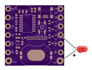
In addition to the built-in LED, you can also connect an external LED. For example, you can connect an external LED between Vdd and pinC7. This way, the external LED will blink at the same frequency as the built-in LED.
If you have a string of parallel LEDs, you should use the power sink pins (pinC4, pinC5, pinC6, pinC7) in order to drive high-current load. The other pins cannot drive more than 25mA of load.
Buttons and Digital Input
The above section deals with digital output. Now let’s look at digital input. Setting a pin as digital input allows the microcontroller to read signals as logic highs and lows. Digital input is commonly used for checking button status. When a button is pressed, the pin value changes from high to low (or reverse). Therefore by reading the input value we can find out whether the button has been pressed. Here is the 04.BUTTON_PRESS demo program which shows how to use the built-in push-button (connected internally to pinA3, a read-only pin).
void main(void) {
    initSquareWear();
    setModeOutput(pinC7);
    while(1) {
        if (buttonPressed()) {
            latC7 = 1;
        } else {
            latC7 = 0;
        }
    }
}
The buttonPressed() function reads the value of pinA3, and returns 0 if pinA3=1 (the pin is normally pulled to high), and 1 if pinA3=0 (when the button is pressed, the pin is tied to ground). The button status is in turn used to turn on or off the built-in LED (pinC7).
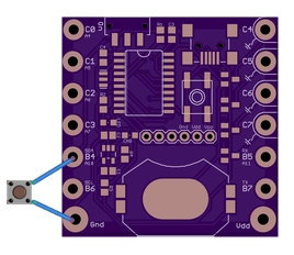
In a similar way, you can check the status of an external button. An example can be found in 05.DIGITAL_INPUT. Usually you should connect one end of the button to ground, and the other end to a digital input pin. Any of SquareWear’s Port B pins (pinB4, pinB5, pinB6, pinB7) has internal pullups, which makes them suitable for connecting buttons without any additional pullup resistor.
Similar to before, checking button status in the inner loop is a waste of computation. Instead, you can use a button interrupt to trigger an interrupt when the button status has changed, such as when it’s pressed or released. This way the main loop can spend most of its time performing other tasks, while occasionally getting interrupted to handle button press. Check 14.BUTTON_INTERRUPT demo program for an example.
Another use of button interrupt is to combine it with the deepSleep() function. This allows the mcu to enter minimal power consumption state, and resume computation when the button is pressed. This way, your project can run over a long time without draining the battery too fast.
Fading LEDs and PWM Output
If you want to control the brightness of LEDs, say, to create fading in and fading out effects, you can use Pulse-Width Modulation (PWM). PWM simulates an analog output (i.e. varying level of voltage) by producing a high-frequency digital signal and adjusting its time share of digital highs (called duty cycle). A microcontroller typically has a some pins that support hardware PWM, but you can also simulate PWM in software. SquareWear has 1 hardware PWM pin (pinC5) and 8 software PWM pins (pinC0 to pinC7).
07.HARDWARE_PWM is an example of hardware PWM (on pinC5). This generates a PWM signal at 11.8kHz with 10-bit precision (i.e. 1024 voltage steps from 0 to Vdd).
06.SOFTWARE_PWM is an example of software PWM. This generates a PWM signal at 183Hz with 5-bit precision (i.e. 32 voltage steps from 0 to Vdd). Compared to hardware PWM, SquareWear’s software PWM has lower frequency, and smaller number of steps. However, this is still sufficient for the purpose of varying LED brightness. The advantage of software PWM is that it can be simulated on any digital I/O pin.
void main(void) {
    byte duty = 0;
    char incr = 1;
    initSquareWear();
    setModePWM(pinC7);  // set pinC7 and pinC3 as PWM output pins
    setModePWM(pinC3);

    while(1) {
        setValue(pinC7, duty);  // set duty cycle
        setValue(pinC3, duty);
        duty += incr;
        if (duty == 31) incr = -1;  // maximum value is 31
        else if (duty == 0) incr = +1;
        delayMilliseconds(100);
    }
}
The inner loop increments PWM value from 0 to 31
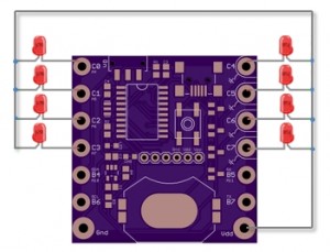
19.FANCY_PWM is a slightly more complex PWM example, which makes use of all Port C pins to create a waving brightness pattern. This example assumes the positive (longer) lead of each LED is connected to Vdd (common source), and the negative lead is connected to each individual Port C pin.
USB Serial Communication
Serial communication comes handy when you need to transmit data or messages between SquareWear and your computer. SquareWear library supports serial communication through the built-in USB port. When enabled, it will create a USB CDC serial port. You can then run a serial monitor to receive/send data from/to SquareWear. First, take a look at the 08.USB_SERIAL_OUTPUT demo:
void main(void) {
    ulong t;
    char msg[8];        // buffer to store display message
    initSquareWear();
    setModeOutput(pinC7);
    openUSBSerial();    // open USB serial port
    putrsUSBSerial("Begin.\r\n");    // write a constant string
    t=millis();
    while(1) {
        if (millis() > t+1000) {
            t = millis();
            ltoa(t, msg);       // convert time to string
            putsUSBSerial(msg); // output to USB serial
            putrsUSBSerial("\r\n"); // carriage return
            latC7 = !latC7;     // toggle pinC7
        }
        pollUSBSerial();        // call this as often as you can
                                // in the inner loop
    }
}
This demo toggles LED at roughly 1Hz and displays the device time (in milliseconds) of every toggle. To use USB serial communication, you should follow the steps below:
- Call openUSBSerial() to create a USB serial port.
- Call putsUSBSerial to send a string (array of characters), putrsUSBSerial to send a constant string (in double quotation marks, and getUSBSerial to receive a string.
- Call pollUSBSerial as often as possible in the main loop to perform pending USB tasks.
Once the USB port is open, SquareWear should show up as a USB CDC device on your computer.
- On Linux or Mac, you do not need any driver. The device will be automatically detected as /dev/ttyACMx in Linux or /dev/ttyusbserial.x in Mac (where x is system assigned number).
- On Windows, you need to install the CDC device driver, available in the inf/ folder under the Uploaders/ directory. Once installed, the device should appear as COMx port (where x is a system assigned number).
-
Note: in case it appears as /dev/ttyUSBx in Linux, you need to unplug the USB, open a terminal window and run sudo rmmod ftdi_sio. Then replug in the USB until it shows up as /dev/ttyACMx.
In order to perform serial communication, you need to run a serial monitor on your computer. First of all, you can use the serial monitor built-in to Arduino or Processing they are both cross-platform. Alternatively,
- On Linux, you can use putty or gtkterm. The typical serial port number is /dev/ttyACM0 but the actual port number may be different. You need to run the serial monitor in sudo, or alternatively add the device vendor and id 04d8:000a to your /etc/udev/rules.d/. An example can be found in folder Uploader/Linux rules.d of the SquareWear repository.
- On Mac, you can use screen or stty. The typical serial port number is /dev/ttyusbserialxxx.
- On Windows, you can use putty. The typical serial port number is COMx.
This does sound complicated and quirky. But once you’ve gone through it, it’s pretty easy to repeat. Additional details can be found in the programming reference.
Another demo 09.USB_SERIAL_INPUT, which shows how to receive messages from a computer. In this demo, when you type in a single digit number, the LED will turn on for that amount of seconds. The code is straightforward and pretty easy to follow.
Analog Input
Analog-digital converter (ADC) allows the microcontroller to read signals that are continuously varying between digital high (Vdd) and low (ground). This is very useful for reading data from sensors, such as light, temperature, humidity, sounds, and all sorts of other sensors.
SquareWear has 6 pins that can be used as either digital I/O or ADC. These are pinADC4–pinADC7, pinADC10 and pinADC11. For example, pinC0 is also pinADC4. To avoid confusion, you must refer to the ADC pin names when using a pin as analog input pin. Let’s look at the 10.ADC_PWM demo first:
void main(void) {
    uint value;
    initSquareWear();

    setModeADC(pinADC4);    // set ADC4 as analog read pin
    setModePWM(pinC7);      // set C7 as PWM output pin

    while(1) {
        value = getValue(pinADC4);    // read 10-bit analog value
        // convert the analog value to 5-bit PWM value and assign it to pinC7
        setValue(pinC7, value>>5);
        delayMilliseconds(5);
    }
}
What’s happening is that the program reads an analog signal from pinADC4, and use that to vary the brightness of the LED (pinC7 PWM). Because analog input returns a 10-bit value (0 to 1023), and software PWM accepts a 5-bit value, a right shift of 5 bits is used to make the number conversion. The higher the analog signal is, the brighter the LED will light up.
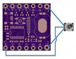
The easiest way to create an analog input is probably to use a potentiometer (pot). A pot has three pins that form a voltage divider. Connect the two outside pins to Vdd and Gnd, and the middle pin to pinADC4. This way, when you rotate the nob on the pot, the output voltage on the middle pin will vary continuously from 0 to Vdd, and the LED accordingly becomes gradually brighter.
The next demo is 11.ADC_BLINK. It’s similar to the above demo, but this time the analog signal is used to control the blinking frequency of the LED. You will notice that the LED blinks faster or slower as you rotate the nob on the pot.
12.ADC_USB_SERIAL reads the analog signal, and sends the reading (a 10-bit integer number) to your computer through USB serial. You can then use a serial monitor to watch the readings, or log the data if you want.
In general, analog input is very very useful. You can find two more interesting demos below in the Pulse Sensor and Temperature Sensor sections.
External Interrupts
External interrupts are triggered by a rising or falling edge of a signal, such as when the signal changes from low to high or the reverse. External interrupts are useful for peripheral devices to notify the mcu that there are tasks to be done. They can also be used to wake up mcu from deep sleep, or for calculating signal frequency.
SquareWear supports two external interrupts on pinC1 (INT1) and pinC2 (INT2). Below is the demo program 15.EXT_INTERRUPT:
volatile int counter = 0;

// external interrupt callback function
void count(void) {
    counter ++;
}

void main(void) {
    char msg[6];
    ulong t;
    initSquareWear();
    openUSBSerial();
    putrsUSBSerial("Begin.\r\n");

    // open external interrupt 1 (pinC1),
    // detect rising edge, use 'count' as callback function
    openExtInterrupt(1, RISING, count);
    t=millis();
    // the main loop displays count value per second
    while(1) {
        if(millis()>t+1000) {
            t=millis();
            itoa(counter, msg);
            putrsUSBSerial("counter = ");
            putsUSBSerial(msg);
            putrsUSBSerial("\r\n");
        }
        pollUSBSerial();
    }

}
This program counts the number of rising edges received on pinC1 in every second, and send the result to USB serial output. The interrupt callback function is count(), which simply increments the counter variable. An important thing to notice here is that is a global variable is to be modified inside an interrupt function, it must be declared volatile.
USART and EEPROM
USART is common way to implement serial communication. Compared to USB serial, USART requires an external USB serial cable in order to interface with a computer. On the other hand, it’s a feature supported in hardware, so it requires much less program memory space than USB serial.
16.USART_OUTPUT and 17.USART_INPUT are two demo programs for USART. They pretty much replicate 08.USB_SERIAL_OUTPUT and 09.USB_SERIAL_INPUT, except they use USART. To make them work, you need to plug in an external USB serial cable (such as FTDI), and connect the TX and RX pins of the cable to RX (pinB5) and TX (pinB7) pins on SquareWear. Then run your favorite serial monitor to read/write data.
18.EEPROM is a simple example to demonstrate using EEPROM. SquareWear has 256 bytes of EEPROM memory, which can be used to store non-volatile data. The demo implements three different LED blinking patterns. Every time you turn on the microcontroller, it increments the pattern index and stores it in EEPROM. So the next time you turn on the controller, it will display the next pattern.
I2C and Flash Read/Write
SquareWear also supports I2C and reading/writing flash memory. These are features already supported in the Microchip C18 Peripheral Library (plib). These programming APIs are quite high-level already. Please refer to the C18 Peripheral Library User Guide for details.
Pulse Sensor
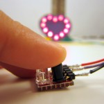
20.PULSE_SENSOR is a demo that shows how to use SquareWear to read and analyze data from a simple IR pulse sensor. To begin, you need to make a pulse sensor, consisting of an IR emitter and receiver (phototransistor). When you press your finger on the sensor, the infared light from the IR emitter will get reflected to the IR receiver. The basic principle is that blood circulation will cause subtle changes in your skin’s reflectivity, which in turn changes the electric voltage on the analog input pin connected to the IR sensor. The program will read the signal from the analog pin, and then perform pattern analysis to figure out a heart beat. Once a heart beat is detected, the program will also blink pinC7 (LED) and calculate the heart rate.
Here are the schematic, diagram, and pictures of the pulse sensor:
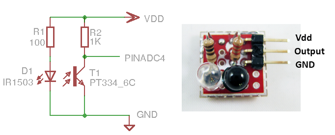
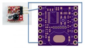
The output of the sensor is connected to pinADC4 by default. In order to check the sensor values, you can change the first line of the program to #define OUTPUT_TO_USB_SERIAL 1. This will enable USB serial output, which allows you to watch sensor values on a serial monitor, or better, use a Processing program to visualize the sensor values. Below is an example:
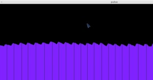 From the visualization, you can see that every heart beat corresponds to a bump in the sensor reading. The demo program uses a simple pattern recognition algorithm to identify the bumps (technically, the points where the sensor values start to drop), thereby identifying your heart beat. In the image, each vertical line indicates when the algorithm has identified a heart beat. The demo program then quickly blinks the on-board LED to follow your heart beat. You can also connect an external LED.
In practice, analog readings are often very noisy, therefore it is necessary to filter the raw data. The demo program uses a straightforward moving average to smooth out the noise and increase the robustness of detection. Please check the program source code for details.
Temperature Sensor
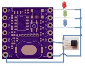
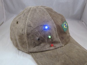
21.TEMPERATURE_SENSOR is a demo that shows how to use SquareWear to read a temperature sensor and visualize the temperature using three colored LEDs. To run this demo, you need a Microchip MCP9700 temperature sensor, and three LEDs: red, green, and blue. The temperature sensor has three pins: Vdd, Vout and GND. Connect Vdd and Gnd to the corresponding pins on SquareWear, and Vout to SquareWear’s pinADC11. The three LEDs use Vdd as common source, and the negative leads go to pinC4 (red), pinC5 (green), pinC6 (blue). The demo will display the three LEDs in different brightness, calculated according to the current temperature. If the temperature is normal, the green LED will be the brightest; the hotter it is, the brighter the red LED will light up; and the colder it is, the brighter the blue LED will light up. So this gives an interesting visualization of the current temperature.
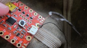
Below is the circuit diagram, as well as a few pictures showing the demo on a hat.
Microchip Application Library Examples
Beyond the demo programs provided in the SquareWear software library, you can also find a number of demo programs in the Microchip Application Library. SquareWear is compatible with the Low-Pin Count (LPC) — PIC18F14K50 configuration. In particular, there are many examples which demonstrate how to use the built-in USB to simulate HID-class devices such as mouse, keyboard, joystick, as well as more complex examples such as implement a health monitor. Feel free to try these on SquareWear.
