Feed on
Posts
Comments

Getting Started

Warning: battery quality and condition vary. Severe discharging may cause some batteries to leak and/or become hot. In case such problems occur, please remove the battery from AASaver immediately. We are not responsible for damage caused by leaking battery.

v2.1

Please follow the AASaver 2.1 User Manual for assembly and usage instructions.


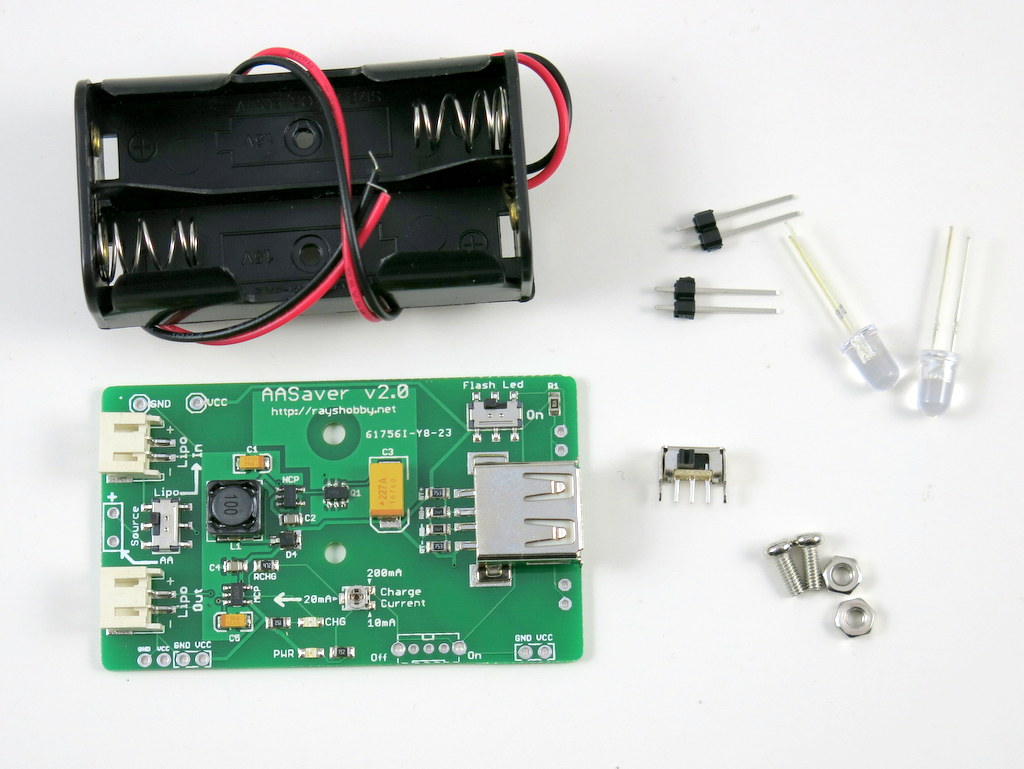
v2.0

Please follow this blog post for assembly and usage instructions.

IMG_2982


v1.1

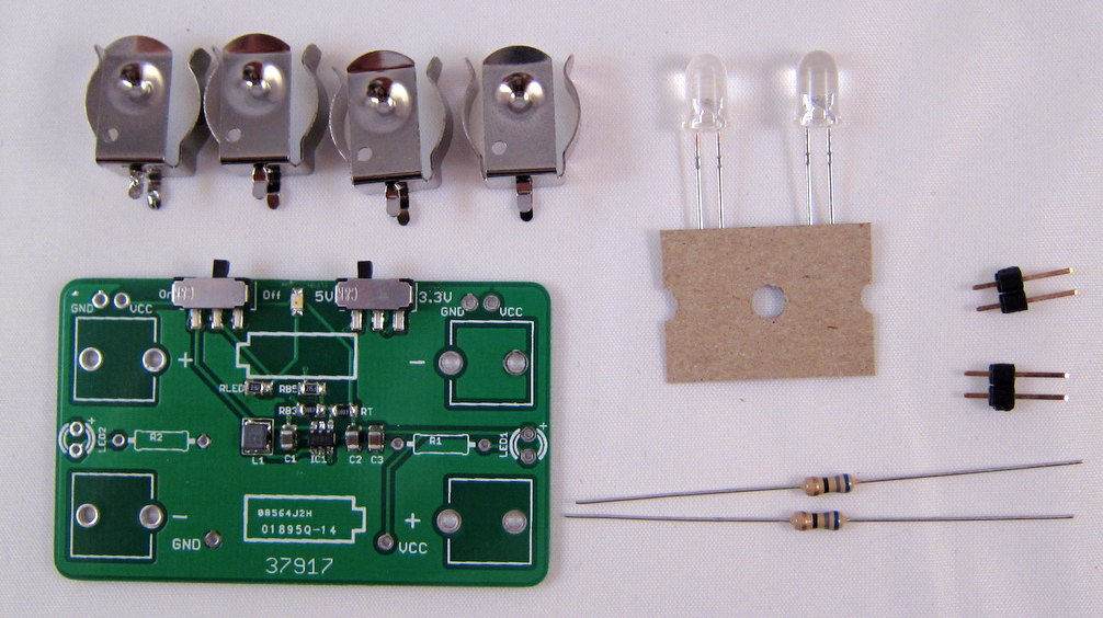
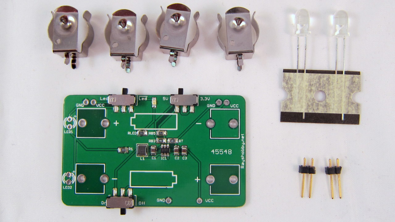
The kit includes a pre-soldered circuit board. To start using it, follow the steps below:

  1. Insert the four battery clips into the PCB holes, and then insert two AA batteries by following the directions marked on the PCB silkscreen.
  2. Turn the power switch to ‘on’. The on-board indicator LED should light up. If not, check if you have inserted the batteries in the wrong direction.
  3. Use the voltage switch to select output voltage: 5V or 3.3V.

Note:: v1.1 has an on-board 39ohm SMD resistor, so no through-hole resistors are needed. In addition, both flash LEDs are moved to the left side so they point to the same direction. A separate LED switch is also added so that it can be used simultaneously as breadboard power supply and LED flashlights. Other than these changes, the rest of the instructions are the same with v1.0 below.


v1.0 (Nov 2011)


LED Flashlight

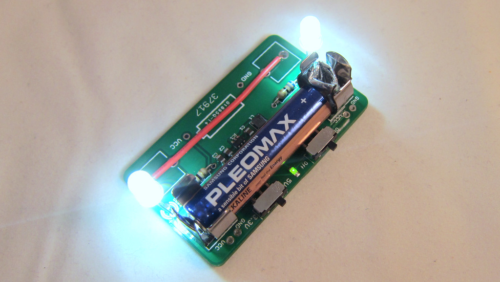
To use the AASaver as an LED flashlight, you should solder the two LEDs and 68 ohm resistors onto the PCB. Pay attention to the polarity of the LED — the longer lead should go into the slot marked by ‘+’. You can decide the height of the LED. You can also solder just one LED, and bend it 90 degrees so that it faces forward. This makes it a bit more comfortable to hold in hand:

LED Brightness. The two LEDs are white-colored with built-in focusing lens. The luminous intensity is rated at 25000 mcd, which is pretty bright. Note that the voltage switch can control the LED brightness: 5V makes them brighter and correspondingly draws more current.


Breadboard Power Supply

To use the AASaver as a breadboard power supply, just solder the two pin headers onto PCB. The spacing between them fits a standard breadboard. To plug it into the breadboard, watch the polarity: make sure the Vcc and Gnd marks on the PCB matches your breadboard polarity. The output voltage can be either 5V or 3.3V, using the voltage selection switch.

Current Output. The maximum output current depends on the condition of the batteries as well as the output voltage. With a pair of fresh batteries, it can output at least 300mA at both voltage levels. Even with old batteries that have been significantly used, it can usually still output a sustained current of 50-100mA @ 5V (and higher at 3.3V), which is sufficient for many breadboard experiments.


Use a Single AA Battery

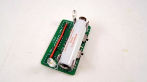
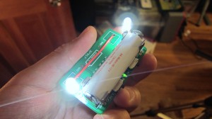
To use a single battery instead of two, just solder a wire between the two outer pins of the bottom battery clips. See the example below. The output voltage remains roughly the same, since it’s regulated. The maximum output current, however, will reduce roughly by half.
Use AAA Batteries

To use AAA batteries, since they are smaller, you need to fill the gap between the battery and the clip. The easiest way is to insert a folded piece of aluminum foil, as shown in the picture below.
22 Responses to “AASaver Use”

  1. bemental says:

    Currently building a solar minty boost with a LiPo charging circuit from Adafruit (https://www.adafruit.com/products/259). How do you think your joule thief would work in conjunction with this circuit?

    I’m thinking of wiring a mini USB plug to your device in order to take these “dead” batteries and vampirically suck any remaining energy to charge a 6600 mAh LiPo that is connected to the circuit.

    Thanks in advance!

  2. ray says:

    @bemental: yes, I think that should work, but I suggest that you set the charging current of the LiPo charger to the lowest possible (100mA according to the webpage you referred to). A pair of old batteries won’t be able to output a lot of current at 5V, so you want to take the juice out of them slowly.

    • bemental says:

      Interesting. Unfortunately, from what I understand the LiPo charger charging current is set by various resistors on the board itself, and since I want to be able to use higher current chargers (either via solar or by USB/wall wort) by reducing to 100mA it would take a very long time to charge the 6600mAh li-ion I have set up with the current design.

      Might I ask what the benefit is of taking the juice out of the batteries slowly VS quickly? Will the transfer be more efficient? The entire purpose of adding the AASaver is to be able to get whatever juice is left out of the AA/AAAs, not power anything for a significant amount of time.

      I’m in the military and we always end up with AA/AAAs lying around that are “nearly dead” because the optics we use require practically fresh batteries to operate properly. Specifically, I’m creating a multi-input rig that will allow me to charge out-of-doors for extended periods of time and I thought it would be nice to add your AASaver to my setup to drain those previously mentioned batteries.

      I purchased one anyway to toy around with if it doesn’t work out. Thanks again for your time and responses!

      • ray says:

        @bemental: I think it’s more of a problem of ‘capability’ than ‘benefits’. When current flows out from a battery, its terminal voltage will drop depending on the condition of the battery. For a new battery, the drop is insignificant, so the output from the voltage booster remain stable even if you are drawing a lot of current from it. For an old battery, however, the drop will be much more significant. For example, an old battery that measured 1.0v open circuit may drop to 0.5v during operation. This can come to a point where even with the voltage booster it can’t output a regulated 5V any more. Hence draining the battery slowly is mainly for keeping output voltage at the desired level, so that it can keep charging your Lipo battery.

        The same problem will happen on solar chargers: a solar cell may have a very high open-circuit voltage, but as soon as you start to drain current from it, the voltage will drop significantly. Keep in mind that to charge a Lipo battery you need at least 0.3-0.7v higher than the Lipo battery voltage in order for the charging to happen. So to keep this going, the only way is to reduce the current draw, and let it charge slowly. Hope this helps.

      • bemental says:

        Thanks a lot Ray, you’ve given me quite a bit of insight in a short amount of time!

        The 6600mAh runs at 3.7V. I’m thinking that the AAS would be a solid addition, even with the voltage concerns. Ideally I would run both the solar and the AAS at the same time but I do see myself utilizing the AAS alone (especially at night).

  3. Michael says:

    Greetings Ray. Love your project.

    May I ask which flavor of the MCP1640 you used (b/c/d), please? So far, I haven’t found anything in the Microchip documentation to describe the differences.

  4. Jerome Dalpe says:

    Thank you so much, I got it yesterday! I’m having loads of fun with this project!
    I’m going to buy more soon!

  5. cae2100 says:

    hey ray, I just got my AASaver today and put it through every test I could think of and it works perfect! I got it for powering a breadboard for my PIC projects and was lerious of if there would be any issues that would mess with the timing crucial stuff like microcontrollers, but its a pure DC signal of 5v. the product works great and anyone that is thinking of getting one of these for your breadboard, go for it, its well worth it. Thanks again ray and hope to see more stuff like this in the future! also kudos for nuts and volts site for pointing me to this awesome device!

    • cae2100 says:

      also something I forgot to mention, the location of the switches on the 1.1 board, I was worried about the board being too big and I’d have to clip off the LED and 3/5v switches to make it fit on the breadboard, but I soldered 2 wires and put them to the bananna plugs at the top of the board and everything fits perfectly there.

    • ray says:

      @cae2100: Glad to hear that it worked for you. Thanks a lot for your comments!

  6. Kris says:

    Hey Ray!
    I just got my AASaver last week and put it together this weekend. It works great! My primary intention was to use it as a flashlight, but it needs a case. Any recommendations?

    • ray says:

      Hi Kris, one possibility is to use a mint tin or mint box. You need to wrap the inside with electric tape or have some kind of insulation to avoid shorting. The reason I recommend mint tin is because its size is appropriate for AASaver and it’s easy to get in grocery stores.

  7. GUlNNESS says:

    Just got in and opened the jiffy bag. Really easy to put together and just testing to see how long x2 LED at 5v will last. Both AA batteries are kicking out about 1.2v each. FREE LIGHT!! The batteries were going to be binned!
    Really good product.!!!
    Q! Why isn’t this circuitry in consumer goods!?!?!?!?!?

    Well done Ray
    A**

    • ray says:

      Thanks for your comment. Boost converter is not a new idea and some consumer products do use it. But mostly manufacturers tend to reduce the product cost by cutting every corner that they feel unnecessary.

  8. Tony B says:

    Dear Ray,
    What is the best or most efficient (for long AAA battery life) boost converter IC, starting at 1.5 v when fresh but drops to 1 volt or less when drained, giving out at least 2.8 – 3 v. To power a small radio, no speakers, just earphones.

    Tnx
    Tony B.

    • ray says:

      Hi Tony, this question is not so easy to answer, because the efficiency depends on a lot of different parameters, including the components quality and their placements on the PCB. I’ve only used a few boost converters so far, including LT1303, MCP1640, NCP1450A, MC34063. Most of these work pretty well, and I don’t have enough to compare between them. But generally the closer the input and output voltages are, the higher the efficiency. For example, converting from 3V to 3.3V generally has much higher efficiency compared to converting from 1.5V to 5V.

  9. Has anybody succeeded with outputting near the maximum current according to the datasheet ?
    I’m trying with MCP1640C (6lead), 4v->5.2V and can’t get it to output 350ma. I’ve got good inductors (4.7uh/2.9A sat.), put 10uF X7R ceramic capacitors near the leads, nothing helps.
    MC34063 has always worked well for me, but in this case I decided to try the higher eff. (over 90% in datasheet) synchronous boost IC.

    • ray says:

      What kind of battery are you using? Keep in mind that the battery has to be new (or more technically must be able to supply sufficient current) in order to get the maximum output current. All AASavers have been tested with new AA batteries and verified to supply 300mA at about 4.8V output voltage.

      • I tried with LAB PSU and 4xEneloop AAs. It turned out that in my device, it doesn’t like:
        1) when output voltage is close to the input – 5.2 vs 5.0V for example
        2) when it’s being started under load (resistive) – around 18 Ohms.
        My device consists of 2 independent boost converters, tied in parallel to supply 700ma. It doesn’t want to start under 9 Ohm load (output is around 2.5v and chips are getting warm). But when i disconnect the load an reconnect it – it works O.K.

      • ray says:

        1) Normally the input voltage should be lower than the output, otherwise the chip will not function as a *boost* converter anymore. If your input voltage is higher, you should use a step-down voltage regulator, instead of a step-up regulator.
        2) I’ve not encountered a problem with starting under load. You mentioned using 2 independent converters in parallel, I’ve not tried that before. But if you need more than 350mA, you should consider using a different voltage converter chip, such as the NCP1450A used in AASaver 2.0. That chip is capable of outputting up to 1 amp.

Leave a Reply