As a kid I was fascinated by the Crystal Radio — the simplest radio that requires no battery or power source. Learning about crystal radio is what got me into electronics in the first place. There are plenty of tutorials you can find online about how to build your own. In this blog post I describe a basic version of the crystal radio, and a couple of simple extensions using modern techniques to improve its quality (although these extended versions all require battery). I won’t talk much about the principles, but instead will focus on making it easily reproducible and a fun weekend project.
(By the way, this is the second of the ‘Learning Electronics’ series. The first one was about the Astable Multivibrator circuit and was posted five years ago… Alas, time flies!)
The Basic Version
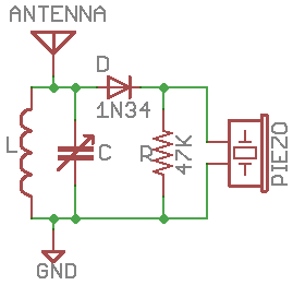
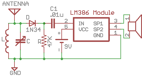
The basic version of crystal radio that I learned as a kid consists of just 7 components as shown below. In fact, the resistor R is optional, making it only 6 components. There is an inductor L, variable capacitor C, diode D, high-impedance earphone (you can use a piezo disc), and antenna and ground. The amazing thing about this circuit is that it has no battery or power source, as the radio signal directly drives the earphone.
Because radio signals are very weak, to make it successful, there are several key ingredients:
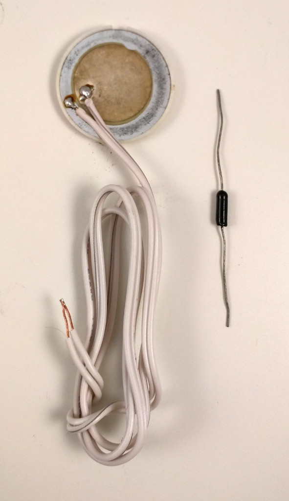
Earphone: you have to use a high-impedance earphone — the typical earbud has very low impedance (less than 32 ohm), which is too heavy a load to drive with direct radio signals. The easiest solution is to use a piezo disc, which has very high impedance and is very cheap. You can then use a thick paper (or better, 3D printing!) to make a cone cover so that you can easily insert it into your ear.
Diode D: use a diode with small forward drop voltage. The classic choice is a Germanium diode, such as 1N34A or 1N60. However, Germanium diodes are difficult to source these days. So if you can’t find a Germanium diode, a small Schottky diode like the common 1N5817 would also work. Again, the point is to use a diode with the smallest forward drop voltage possible.
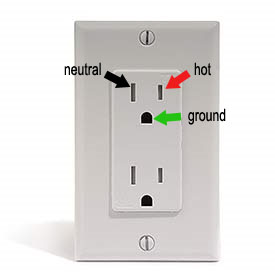
Antenna and Ground: a good antenna is critical for crystal radio. The antenna should be set up outdoors if possible. I implemented mine using a long single stranded wire and ran it around the perimeter of my porch. It worked quite well. As for ground, I just inserted a wire into the ground hole of a 3-prong wall socket. Be careful: make sure it stays reliably in the ground hole. If the wire touches the hot socket, it will be extremely dangerous!
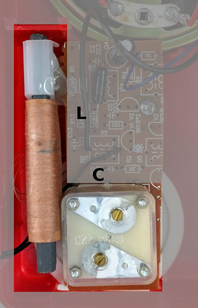
Tuning Circuit: inductor L and variable capacitor C form the tuning circuit. These are pretty easy to find in an old radio or a DIY radio kit (as shown in the picture above). A lot of the inductor coils you can find have both a primary coil and secondary coil. You can use just the primary coil, or connect the primary and secondary in series. Similarly, a lot of the variable capacitors have two sections. You can use either section, but to help increase the frequency range of reception, you can connect the two sections in parallel.
The best time to try the crystal radio is probably at night, when there is less electro-magnetic interference in the air and the ambient noise is low. Slowly turn the dial on the variable capacitor and listen carefully. If there is a strong local AM station, you should be able to hear it. If you can’t hear anything, don’t worry, read on and you can find how to use a simple audio amplifier module to help you hear weak channels.
LM386 Audio Amplifier Module
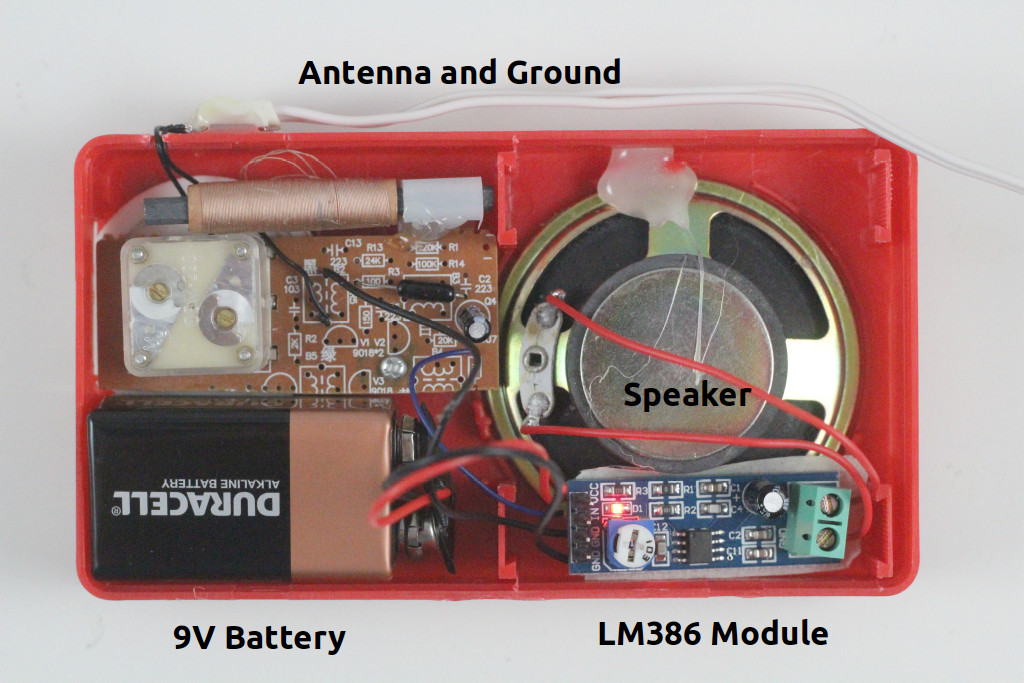
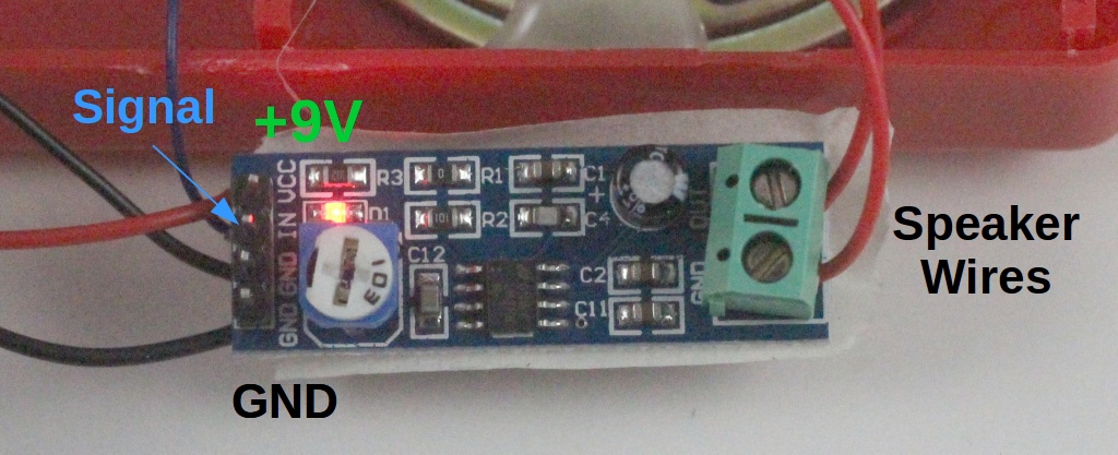
The first time I heard something from the crystal radio, it was really exciting. But the volume is just too small to keep enjoying it. After a bit of Googling, I found a simple audio amplifier chip LM386, which can easily amplify the radio signal to be played on a speaker. It’s pretty easy to build the circuit myself, but there are ready-made LM386 modules that you can find on eBay and Amazon, for only a couple of bucks. So I bought one. Soldered a few wires, connected a standard 8 ohm speaker, and plugged in a 9V battery: wow, now you can hear the radios loud and clear, much better! Below is the updated schematic and a picture showing the wiring:
TA7642 Radio IC
With LM386, the sound is loud and clear. But there is still one problem: the antenna and ground wires are very cumbersome, and make the circuit non-portable. I did some more Googling, and found a simple radio IC called TA7642 that can amplify and detect AM signal, eliminating the antenna and ground wires. TA7642 is a 3-terminal IC shaped like a transistor. It’s quite simple to use and can work at a voltage as low as 1.2V, which is ideal for battery power. You can buy it from eBay or Amazon. I got mine from the Chinese website Taobao, for a jaw-dropping price of 20 Chinese cents (about 3 US cents). Below is a typical circuit of TA7642 that works with high-impedance earphone. It is powered by a single AA battery:
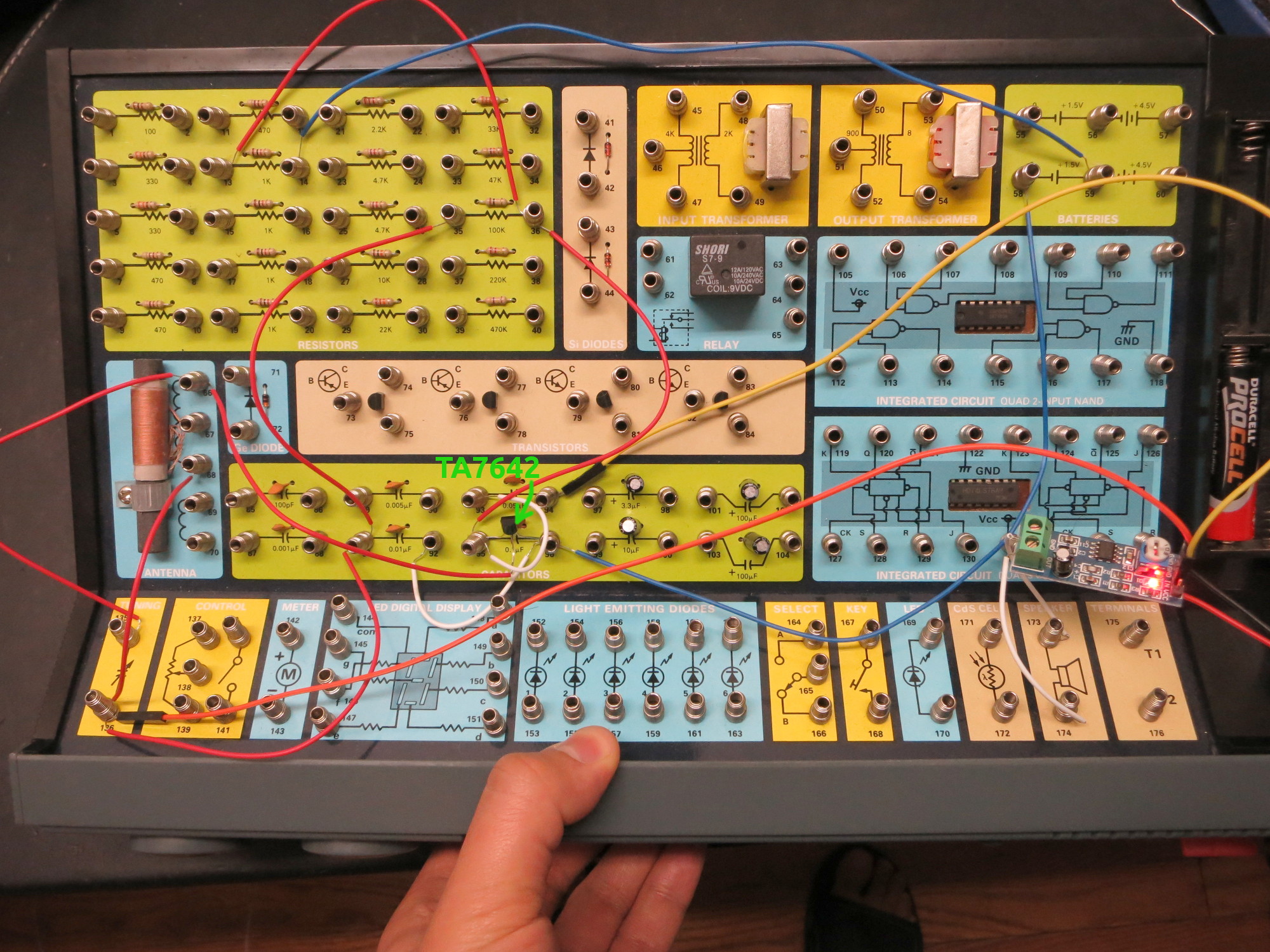
This time the antenna and ground wires are gone, so the circuit becomes portable. To hear the sound through a speaker, you can again use the LM386 audio amplifier. Because LM386 requires at least 5V, it won’t work with a single AA battery. But it’s common to use a 9V battery to power the whole circuit, and two diodes in series to create the 1.5V operating voltage that TA7642 needs.
I implemented the circuit using an electronic experiment kit, which has most of the components I needed. I can easily make a custom PCB to fit everything in a small enclosure. At night I can hear about 3 to 4 stations. Cool!
DIY Radio Kit: so after I built the circuit, I discovered that Elenco sells a $15 DIY Radio Kit that is essentially the same circuit as I learned above (i.e. TA7642 + LM386). So if you want a kit that includes all the components, this is a very decently priced kit to buy.
Along my search, I also found some DIY Radio Kits from Taobao, like this six-transistor radio, and seven-transistor radio. For less than $2, these kits include PCB, all components, speaker, and even an enclosure! What a crazy price!
It was a lot of fun to re-live my childhood passion by learning to build the crystal radio again, with some modern touches. The experiments above are quite easy to reproduce, and hopefully they provide inspirations for you to try them out as well.
After I released the ESP8266-based OpenGarage, there has been a weird bug that kept bugging me: a small fraction of the controllers (let’s say 1 out of 10) would crash on restart, and that leads to an infinite reboot cycle. Once this happens, it seems there is no way to stop it until you reflash the controller with NodeMCU firmware, and then flash OpenGarage firmware back. It’s completely crazy because first, this issue is hard to reproducing — most controllers would work just fine, but once in a while, one would go nuts; second, upon crashing you can check the stack dump but the information is basically gibberish and does not help debugging at all; third, just reflashing the OpenGarage firmware itself is not sufficient — something seems to have been permanently altered in the flash memory such that you have to flash a completely different firmware (NodeMCU for example) to stop it; finally, even this is not a permanent fix — if you reboot the controller regularly for a few times, this issue will eventually happen again.
For the longest time I thought there is a bug in the OpenGarage firmware code that causes this to happen. But the above symptom defies any standard reasoning and explanation. This has kept bugging me until yesterday, I finally sat down and did a number of reproducible tests that helped me finally figure out the cause. It turns out this has to do partly with the ESP8266 hardware quality and partly software. The short story is that every time ESP8266 restarts, the firmware (more specifically, ESP8266 Arduino library) writes the current WiFi SSID and password to flash memory (along with other flash memory operations such as reading config files); over time this may cause a corruption at some point (possibly due to flash memory quality); once this happens, it will keep crashing on restart, and the only way to stop it is to erase the corrupted region (that’s what reflashing NodeMCU firmware accomplishes).
In fact, this issue has already been reported in the ESP8266 Arduino forum. I wish I had discovered this earlier. The solution is actually quite straightforward: simply add WiFi.persistent(false); right at the beginning of the code, that will stop the library from writing SSID and password to flash memory every time. This is unnecessary anyways since OpenGarage firmware already stores SSID and password in the config file.
This simple trick seems to have magically fixed the annoying bug. To be fair, I believe this bug only happens when you manage WiFi SSID and password separately in a config file stored in flash memory space — if the SSID and password are hardcoded into the firmware the issue wouldn’t happen. In any case, I wrote this blog post to document the issue and fix, and hope this may be useful for others who encounter similar issues with ESP8266.
We’ve recently found a technical issue with Blynk’s QR code scan feature that makes the Blynk app not work properly on some iOS devices. The symptom is that the app can receive push notifications but the distance value, read count, and LCD widget are not updating. Please check this forum post for solutions. This seems to only affect iOS devices.
Blynk connection issue: recently Blynk updated their cloud server, causing Blynk app to not be able to communicate with OpenGarage. The solution is to update OpenGarage firmware to 1.0.4.
Today I am very excited to introduce you to OpenGarage — an open-source, universal garage door opener built using the ESP8266 WiFi chip and the Blynk app. I’ve wanted to finish this project for a while, as there have been multiple occasions where I left the house in a hurry and forgot to close my garage door, or locked myself out of the house, or had to let a friend or handyman in while I was away. Having a WiFi-based garage door opener (which I can access remotely using my mobile phone) would be super convenient. Recently as I started learning about ESP8266, I found it to be the perfect platform to help me complete this project.
A quick note: this blog post is temporarily the main landing page of opengarage.io. A more professional-looking site is under construction and should be ready soon. Also, the first production run has been ordered, and they should be ready to ship in 2 weeks of time. If you are interested in OpenGarage, you can place your order at rayshobby.net/cart/og.
Here is a video introduction that gives you a quick walk-through:
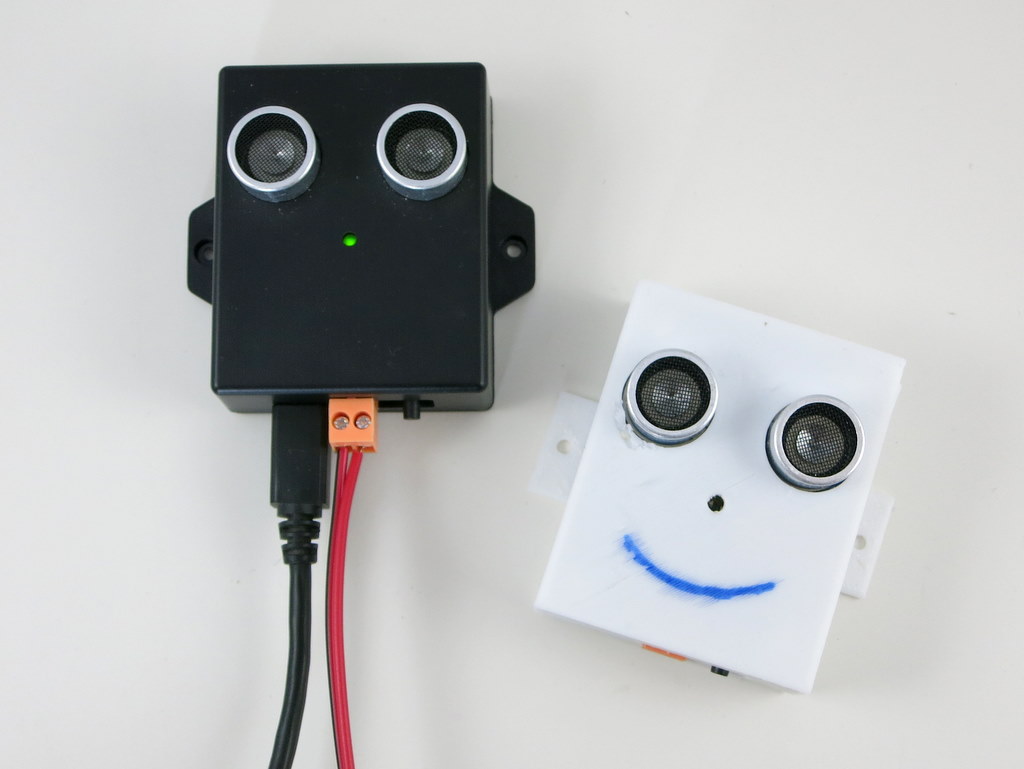
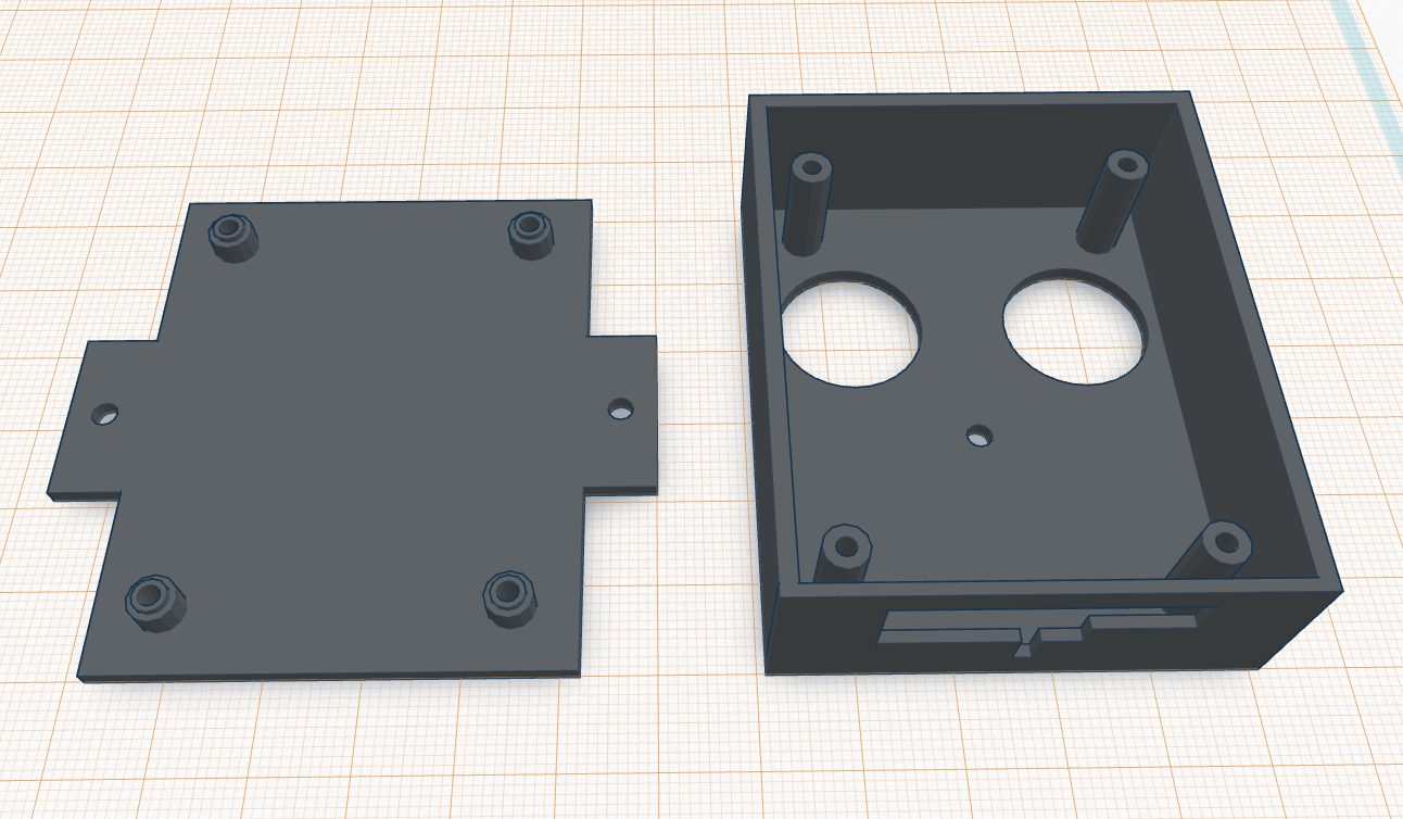
Here are some head shots of the OpenGarage controller:
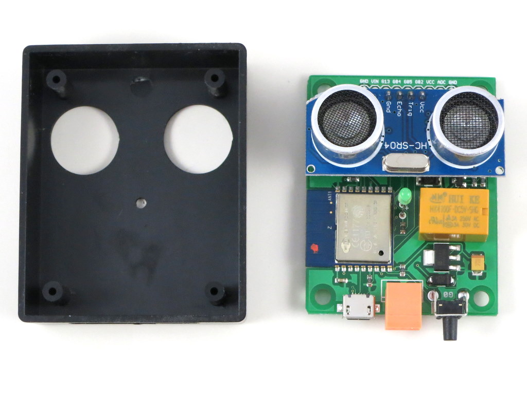
I made the prototype version using a 3D printed case, and the final version using an off-the-shelf case with custom cutouts. Two pictures of the circuit board are shown on the right above. With OpenGarage, I can now check my garage door status wherever I am, open or close the door remotely, and check the record of recent events through the log and history graph. The controller supports a built-in web interface with embedded HTMLs, and remote access through the Blynk app. The built-in interface is used for local access and changing configuration/settings, while the Blynk app is used for remote monitoring and control.
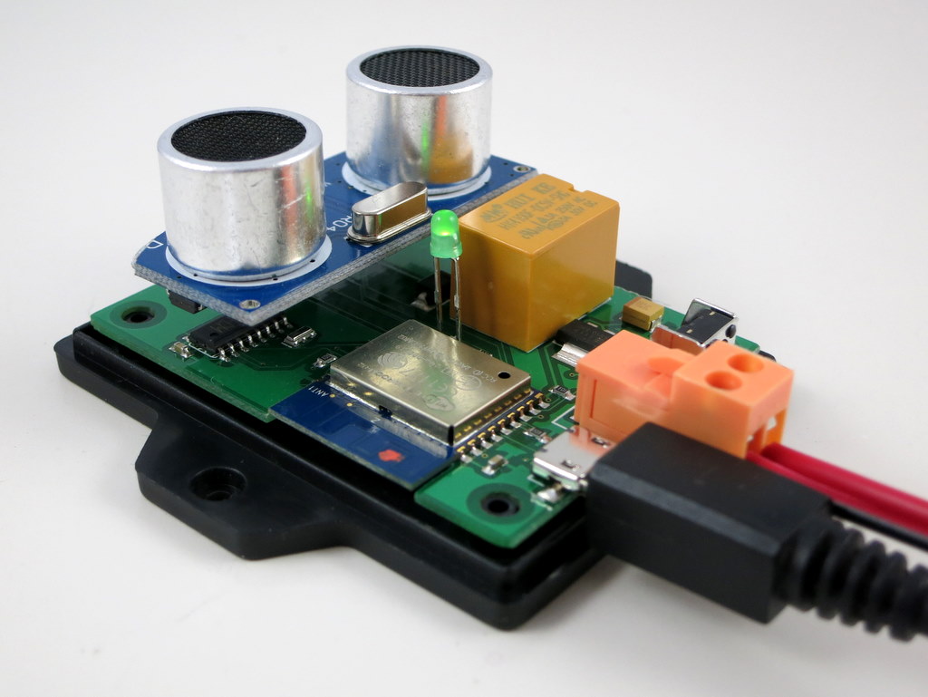
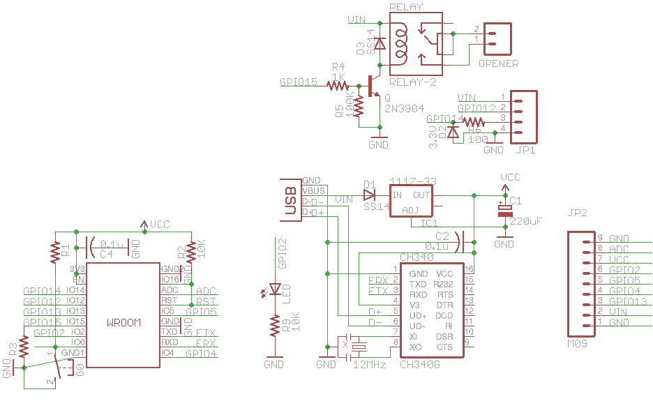
Hardware-wise, it’s really simple. It consists of:
an ESP8266 (WROOM-2) WiFi chip;
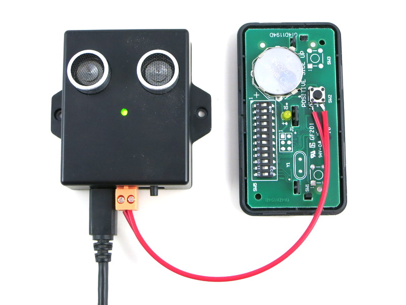
an ultrasonic distance sensor (HC-SR04);
a relay (for triggering garage door actions);
a pushbutton and indicator LED;
a microUSB connector and CH340G USB-serial chip.
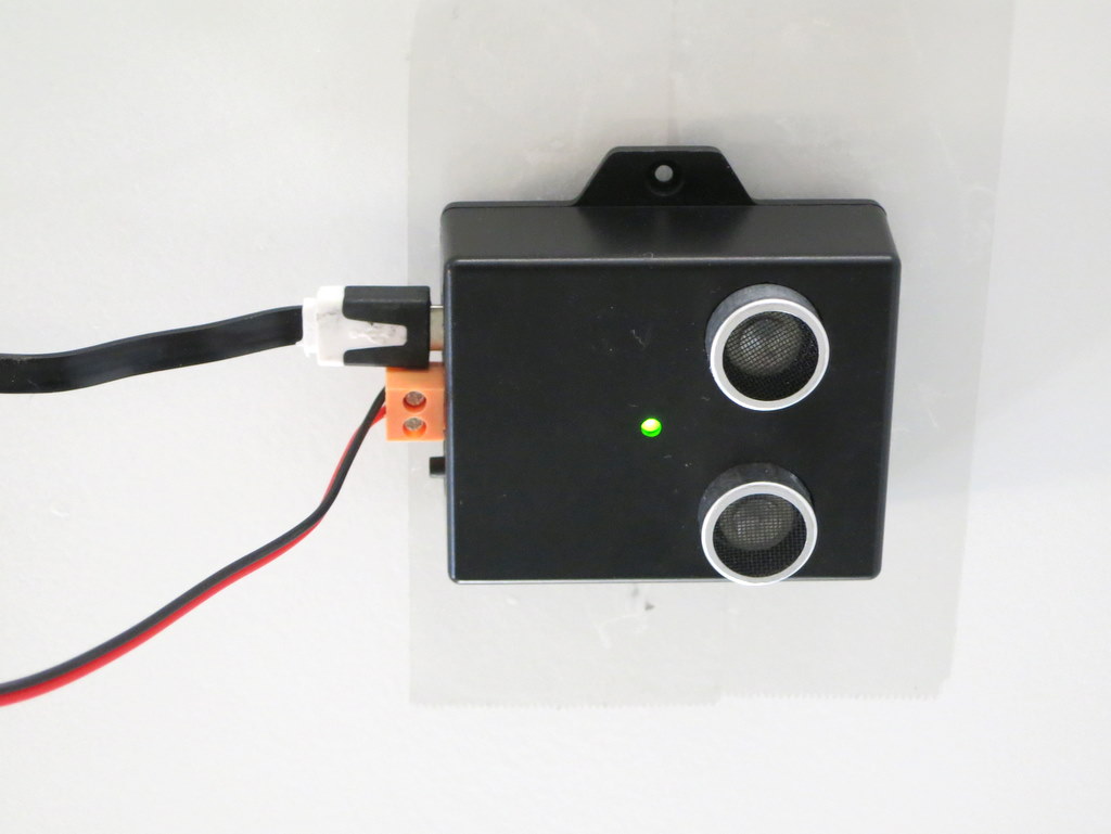
Mounting. The controller is typically mounted to the ceiling at the garage, with the distance sensor facing down. When the garage door is closed, it reads the distance to the ground, or the top of your car if you’ve parked in the garage. When the door opens and comes up, the sensor reads the distance to the door, which is a much smaller value. So by checking the distance value, it can tell if the door is open or closed. The distance value can also tell you if your car is parked in the garage or not, which is an additional benefit that can be useful at times.
For roll-up garage doors, the ceiling mount would not work. Instead, you can mount it to the side of the door, with the sensor facing the outside. This way the logic is reversed: if the distance reading is small, it means the door is closed, and vice versa.
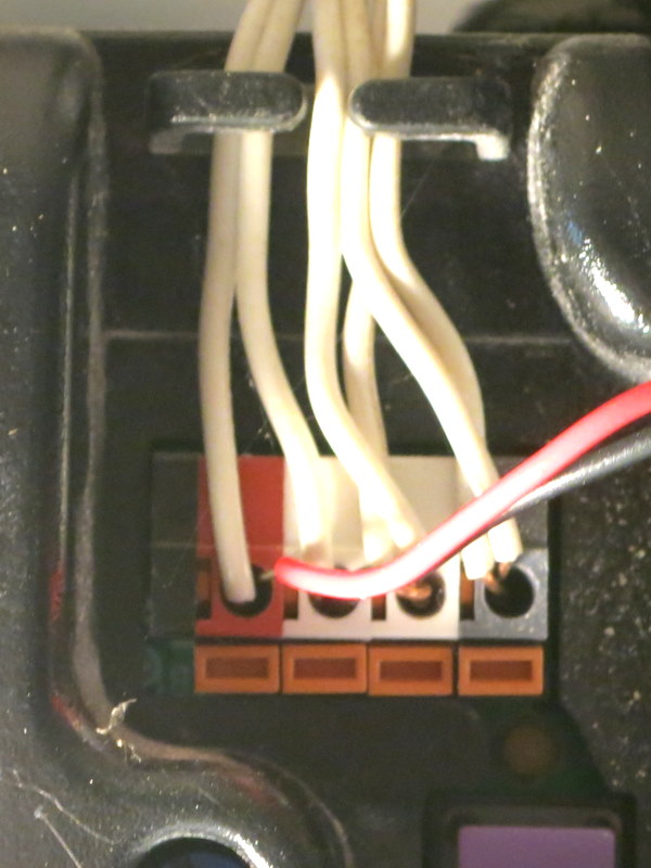
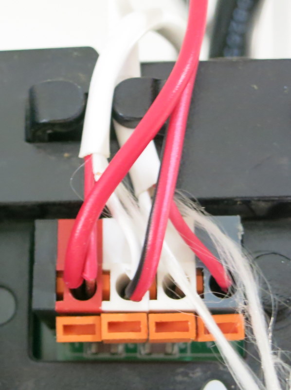
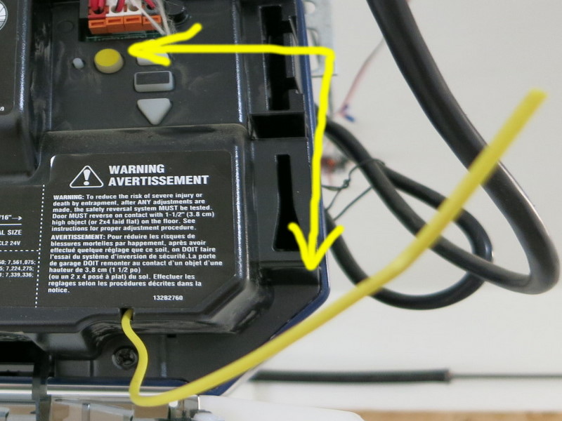
Interfacing with Garage Door System. OpenGarage uses a relay to simulate door button clicks. For most garage door systems, you can simply connect the two wires from the OpenGarage controller to where you would normally insert your door button wires into. The only exception is the most recent Security+ 2.0 systems, which come with a yellow learn button and antenna. These openers use secure door button codes, but you can still interface with them through a compatible door button.
Alternatively, you can take apart an existing garage door remote, solder two wires to the button, and connect these two wires to OpenGarage. This way, the relay clicks simulate pressing the button on the remote. As long as you have a remote that works with your garage door system, this approach would always work.
Web Interface and Blynk App. The controller has a built-in web interface with embedded HTMLs, implemented using JQuery Mobile. It’s used for WiFi setup, local access (directly using IP) and changing configurations/settings. The controller also supports remote access through the Blynk app, which is a cloud-based service that’s really easy to use. Before proceeding, it’s recommended that you install the Blynk app, create an account, log in, and scan the OpenGarage app QR code to replicate the project inside Blynk. Then go to the project settings and copy the authorization token (32-digit hex code). This way, immediately after the setup step, you can use Blynk to access OpenGarage.
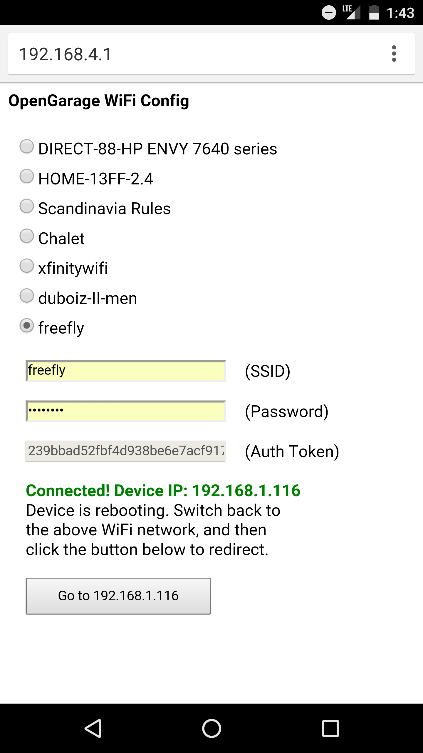
Initial Software Setup. OpenGarage is powered by a microUSB cable. At factory default settings, it boots into Access Point (AP) mode, creating an open WiFi network named OG_xxxxxx (where xxxxxx is the last 6 digits of MAC). Use your phone or a computer to connect to this network, and then open a browser and type in 192.168.4.1 to access the AP homepage. You will see a list of nearby WiFi networks scanned by the controller. Select (or manually type in) the ssid, input the password, and paste the Blynk token (if you don’t have it, just leave it empty). Then click on ‘Connect’. The controller will go into AP+STA mode, attempt to connect to your router, and report back its assigned IP address.
Once connected, it will reboot into STA-only mode. At this point, switch your phone back to your home WiFi, and click the redirect button (or manually type in the assigned IP) to access the device homepage.
LED and Button Functions. The LED serves mainly as an indicator: in AP mode, the LED blinks rapidly; and in station mode, the LED blinks briefly when the controller reads the distance sensor, which is once every few seconds (configurable). The button (connected to GPIO0) has the following functions: a short click triggers a relay click; and a long press triggers a factory reset (see below). The button can also be used to enter bootloading mode: if the button is pressed when the controller is powered on, ESP8266 will enter bootloading mode. This is useful if you want to upload a firmware through USB (instead of using OTA update).
Reset to Factory Default. At any point, you can press and hold the pushbutton for 5 seconds or more until the LED stays on, then release the button to reset the controller back to factory default.
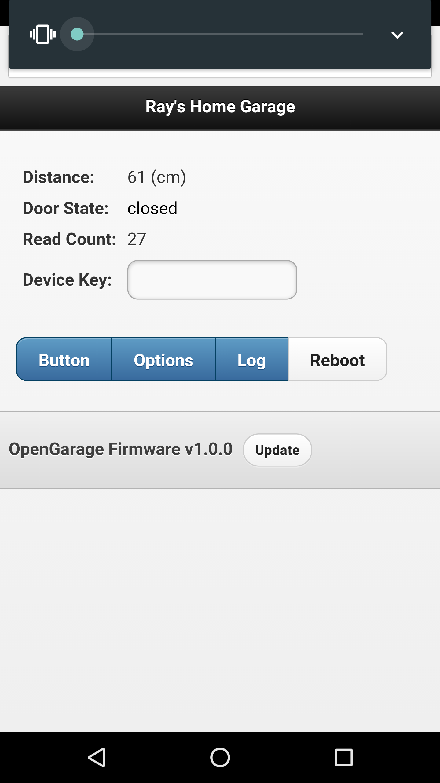
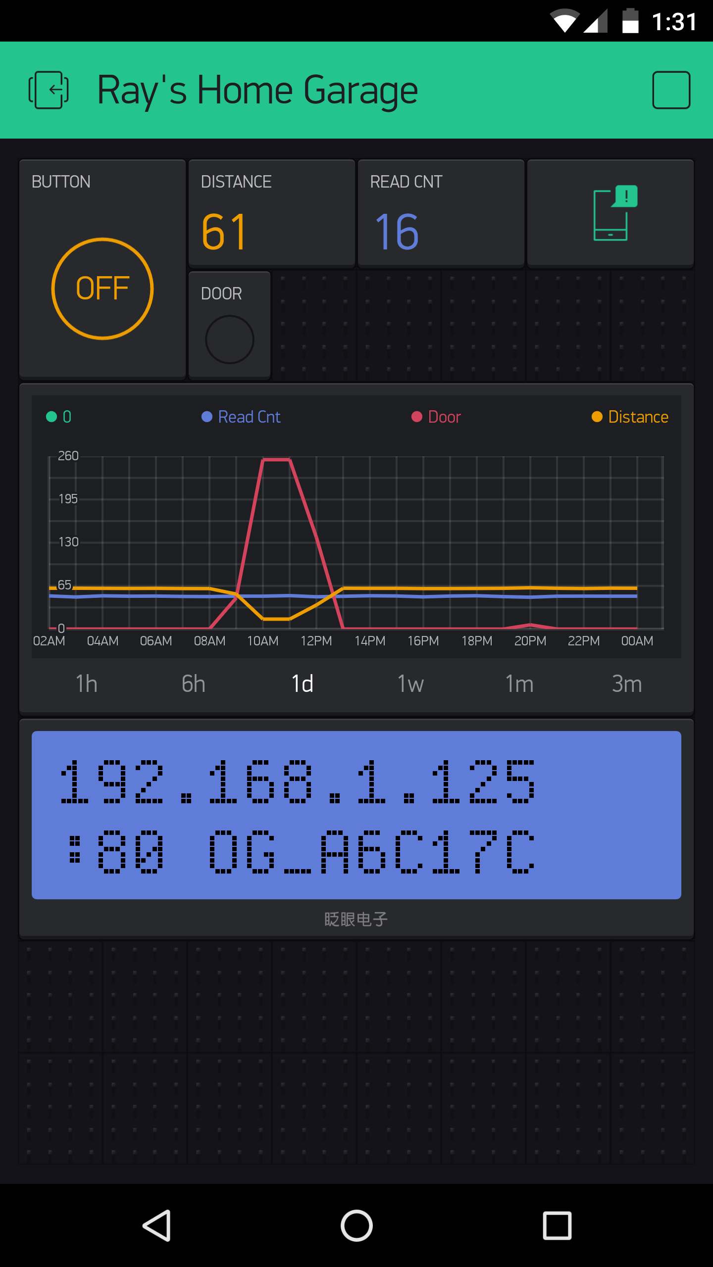
Built-in Web Interface. At the homepage you can check the distance readings, door status, and a read count value which increments every few seconds as the controller reads the distance sensor. The read count is basically a ‘heart beat’ that indicates if the controller is communicating with your browser or not. You can trigger a button click or reboot the controller. These actions are protected by a device key, which is by default opendoor.
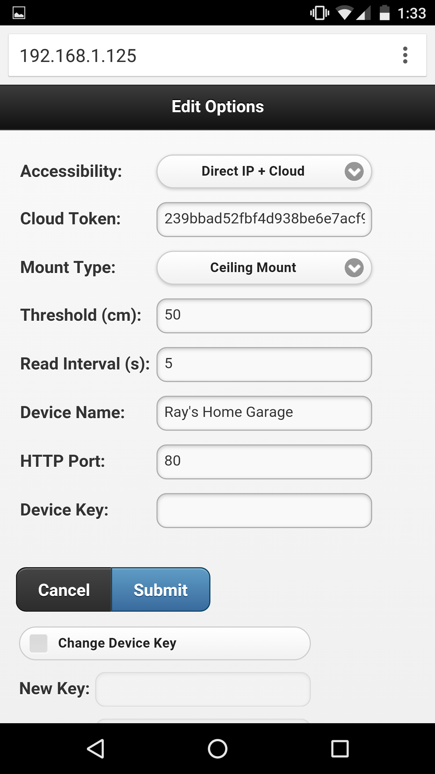
Click the Options button to open the ‘Edit Options’ page. Most of these are pretty obvious. The one you may need to tweak is the distance threshold, which the controller uses to tell if a door is open or closed. Basically, measure the distance from the sensor to the door (when it’s fully open), and that to your car, and pick a value in between the two. The settings are all saved in a configuration file in the flash memory, so they won’t get lost when the power is down.
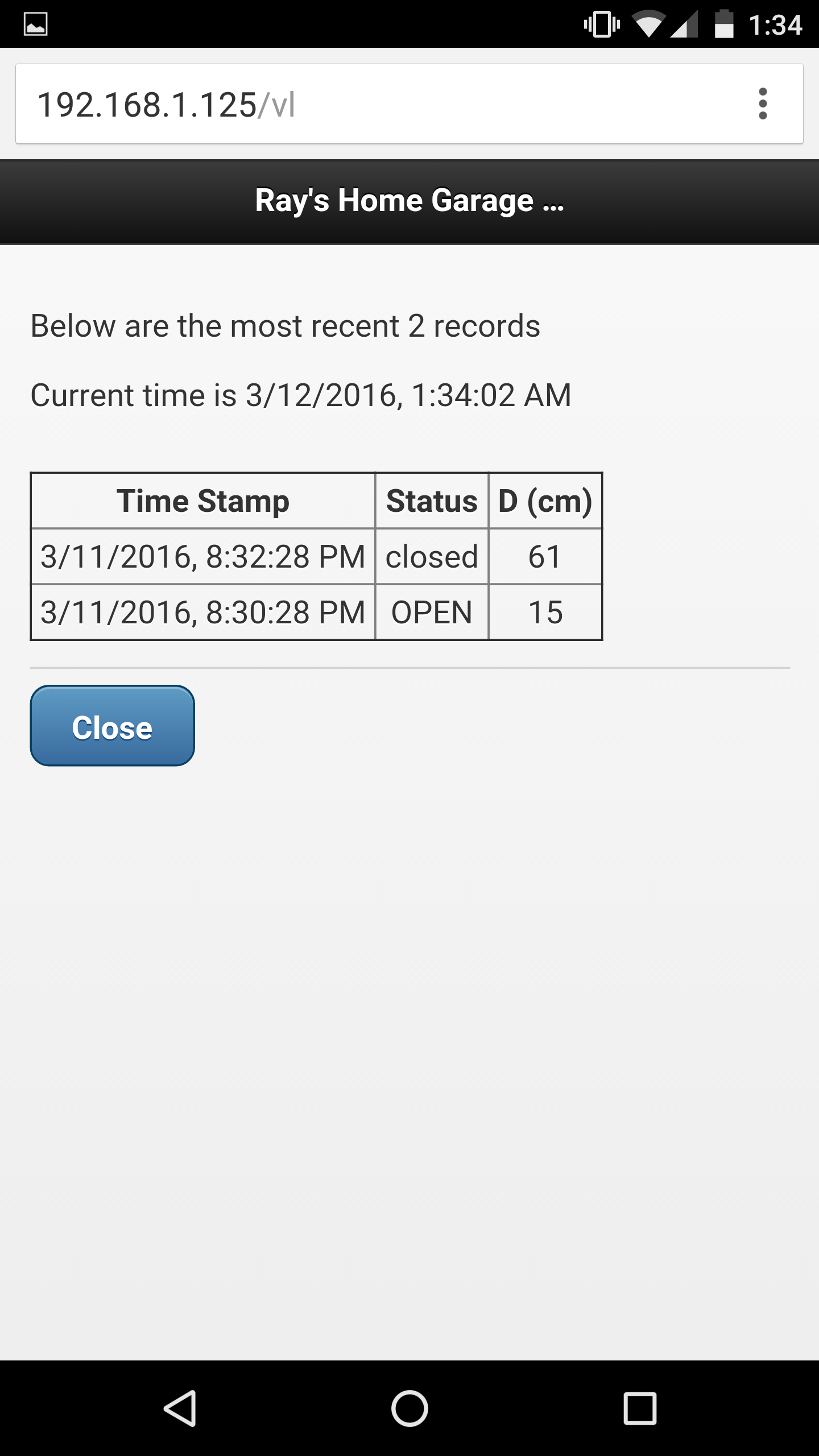
At the homepage, click the Log button to open the log page. There you can see the list of recent events. The homepage also shows the current firmware version. Next to the version number is an ‘Update’ button, which allows you to upload a new firmware through the web interface (thanks to the OTA update feature available to ESP8266).
Blynk App. For remote access, the Blynk app is really easy to use. Once you’ve set a token, OpenGarage will communicate with Blynk’s cloud server and report its status. Like the built-in web interface, the app allows you to check distance readings, door status, and trigger a button click. Additionally, it provides a history graph that visualizes previous events, and push notifications when the door opens or closes (note that Blynk limits push notifications to no more than one per minute).
Resources and Technical Details
I’ve published the hardware design files and firmware code in Github. Those who are interested in the technical details can go to:
to find out all the low-level details. These include the circuit schematic and PCB (in EagleCAD format), 3D model of the enclosure, OpenGarage Arduino library, and instructions to compile the firmware. If you are interested in modifying the 3D printable enclosure, go to tinkercad.com, log in, and search for ‘OpenGarage’ and you should find the 3D model I created there.
If you want to extend the functionalities of OpenGarage, there are several spare pins which are mapped out on the PCB for adding additional sensors etc.
Overall it has been a very pleasant experience using ESP8266 for this project. It’s inexpensive, powerful, and has active community support. I can’t think of any reason why not to use it for all my future projects 🙂
If you are interested in buying OpenGarage, you can place your order at rayshobby.net/cart/og.
Use the web interface to update firmware (click the Update button at the bottom of the homepage or Options page).
If the built-in web interface is not responding, do a factory reset (i.e. pressing the button for 5 seconds or more), then follow the setup steps but leave the cloud token empty (to avoid any potential Blynk connection issues). Once firmware is updated, go to the Options page and put in the Blynk token, make sure the Accessibility is set to ‘Direct IP + Cloud’.
If neither of the above work, you can use a USB cable to flash a new firmware (see instructions below).
After updating firmware, check the bottom of the homepage and make sure the firmware version is correct.
Linux: driver is not required, but you need to run all following commands as root or with ‘sudo’.
Step 2: Bootloading mode and serial port.
Let the device enter bootloading mode. To do so, get a microUSB cable, plug the smaller end to the device’s USB port, then press and hold the pushbutton while plugging the cable’s other end to your computer. The LED light should stay on constantly, and you should not hear any buzzer sound. If not, unplug the USB cable and redo this step.
Next, the device should appear as a serial port and you need to find out the serial port name:
Windows: the serial port name is COM? where ? is a number. You can find out the port name in the notification area, or in Device Manager — Serial Port.
Mac OSX: the serial port name is /dev/tty.wchusbserial? where ? is a number. You can find out the port name by running ls /dev/tty.wch* in Terminal (i.e. command line).
Linux: the serial port name is /dev/ttyUSB? where ? is a number. Run ls /dev/ttyUSB* in command line to find out.
Step 3: Reflash firmware.
Download the OpenGarage reflash package and unzip it. The package includes esptool, nodemcu firmware, and OpenGarage firmware. Open a Terminal (i.e. command line window), cd to the folder where you unzipped the package. Depending on your operating system, run the following command (assuming the device is in bootloading mode):
Windows: esptool.exe -cd ck -cb 230400 -cp COM? -ca 0x00000 -cf nodemcu.bin
where COM? is the serial port name you found in Step 2 above.
Mac OSX: ./esptool_mac -cd ck -cb 230400 -cp /dev/tty.wchusbserial? -ca 0x00000 -cf nodemcu.bin
where wchusbserial? is the serial port name you found in Step 2 above.
Linux: sudo ./esptool_lin32 -cd ck -cb 230400 -cp /dev/ttyUSB? -ca 0x00000 -cf nodemcu.bin
where ttyUSB? is the serial port name. If you use Linux 64-bit, use sudo ./esptool_lin64 instead.
If you encounter any error, check if the device is in bootloading mode. Repeat Step 2 to enter bootloading mode before flashing.
Finally, once the nodemcu firmware is flashed, re-enter bootloading mode (Step 2) and run the above esptool flashing command again, except replacing nodemcu.bin at the end with og_1.0.4.bin. This completes the firmware reflashing.
My fortune cookie last night said I have recently left many things undone, and at this rate I may never get them done. Quite alarming indeed. One of the things I haven’t done well recently is regular posting on this blog. So I’ve decided that before the year ends, I have to remedy this by writing a couple of new posts.
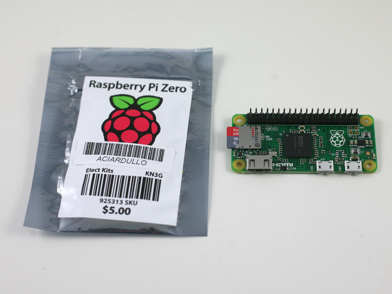
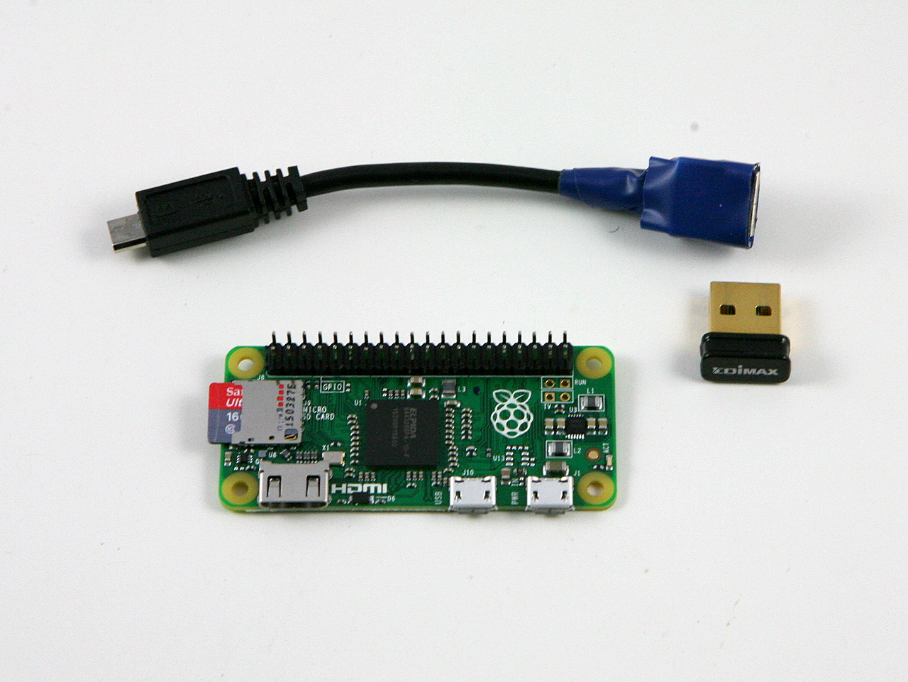
The first order of business today is Raspberry Pi Zero. I am sure many of you have heard of it, which is the latest new comer in the Raspberry Pi family, and it has a jaw-dropping price of $5. Five dollars for a tiny computer that runs a full Linux system, how amazing is that! Well, since announced, it’s in such high demand that it went out of stock at most online stores. I’ve been waiting to get my hands on one for a while. A few days ago I was visiting friends in Long Island, New York and discovered that surprisingly I can get the Zero from Micro Center retail stores. So I went and purchased one in their Westbury store. It took me a while to find it in a locked cabinet, and apparently it’s limited to one board per customer. It’s such an anomaly, because normally things in high demand and so difficult to get would be very pricey, but this is only $5!
The main reason for me to get one is to verify if it works well with OpenSprinkler Pi, as several customers have asked me. The answer is yes, as the video demo below shows. But before you decide to dive in, you should be aware of the hidden costs, which can quickly add up. First, to reduce cost the Zero does not have the 2×20 pin headers pre-soldered, and it doesn’t have a standard size USB connector. This means in order to use it with OpenSprinkler Pi, you need to hand solder the pin headers; and in order to connect it to a USB WiFi dongle, you need a microUSB to USB adapter, which is commonly known as the OTG (USB On-the-Go) adapter. If you are not willing to go through the hassle, you’d be better off staying with Raspberry Pi A+, which is only $20.
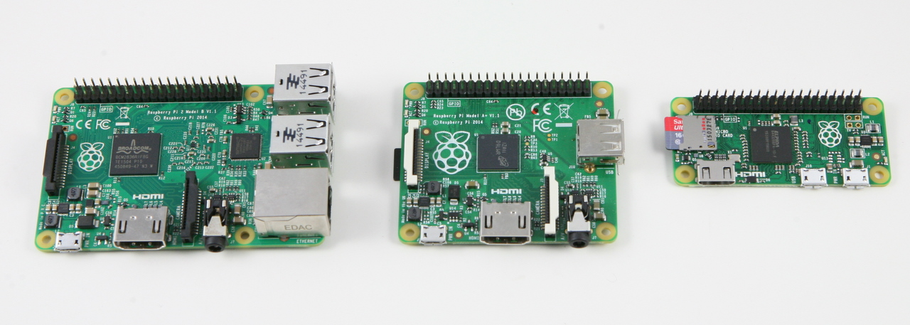
Here is a display of three Raspberry Pi’s: version 2 model B, A+, and Zero.
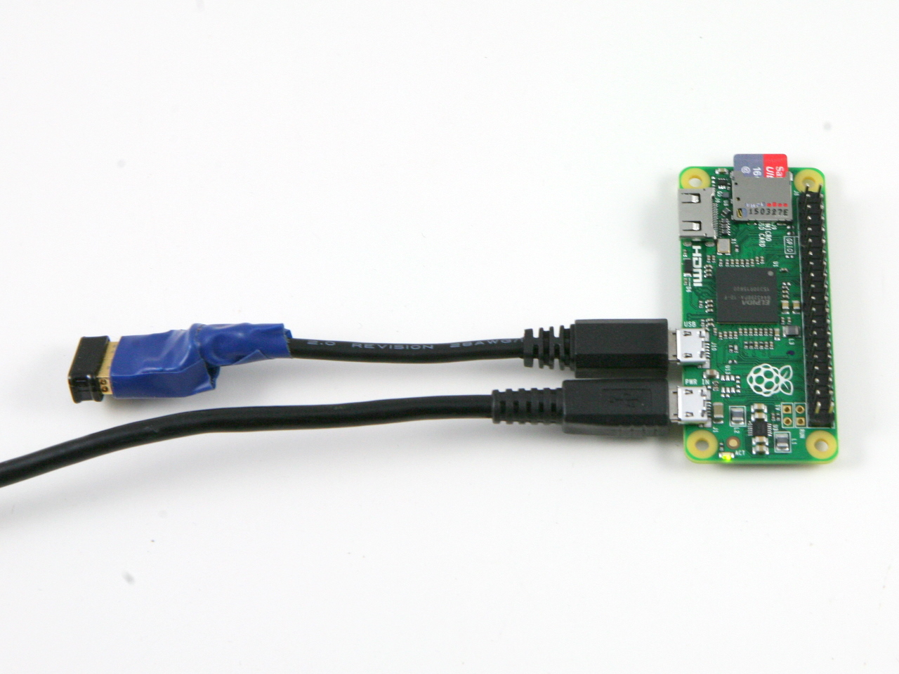
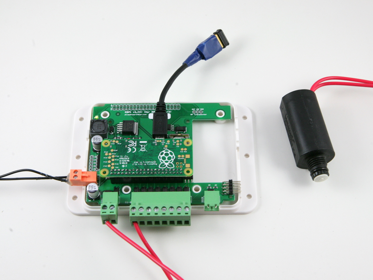
The OTG adapter I ordered hasn’t arrived yet, so I decided to make one myself. It’s quite easy: just cut the connectors from an existing microUSB cable and USB extension cable (which has a USB A female connector), strip them, solder the four internal wires with matching colors, and use some hot glue and electric tape to fix everything in place. I then burned a new microSD card (with the latest Raspbian image) and installed the OpenSprinkler firmware. Plug it into the OpenSprinkler Pi circuit board, and insert 24VAC power supply: Voilà, it boots up in under a minute and I can start turning on and off sprinkler valves right away. There you go, it’s verified! For those who want to see real actions, check out the Youtube video below.
Currently the OpenSprinkler Pi circuit board doesn’t have screw holes that match those on the Zero. The consequence is that the Zero won’t have much physical support other than the 2×20 pin header, which is pretty tight and does provide reasonable support. I will have to modify the board design to incorporate the screw holes. I am half hoping that the Raspberry Pi foundation would release a new version of Zero with the pin headers pre-soldered and a standard size USB connector. Not sure if this will ever happen, but we will see!
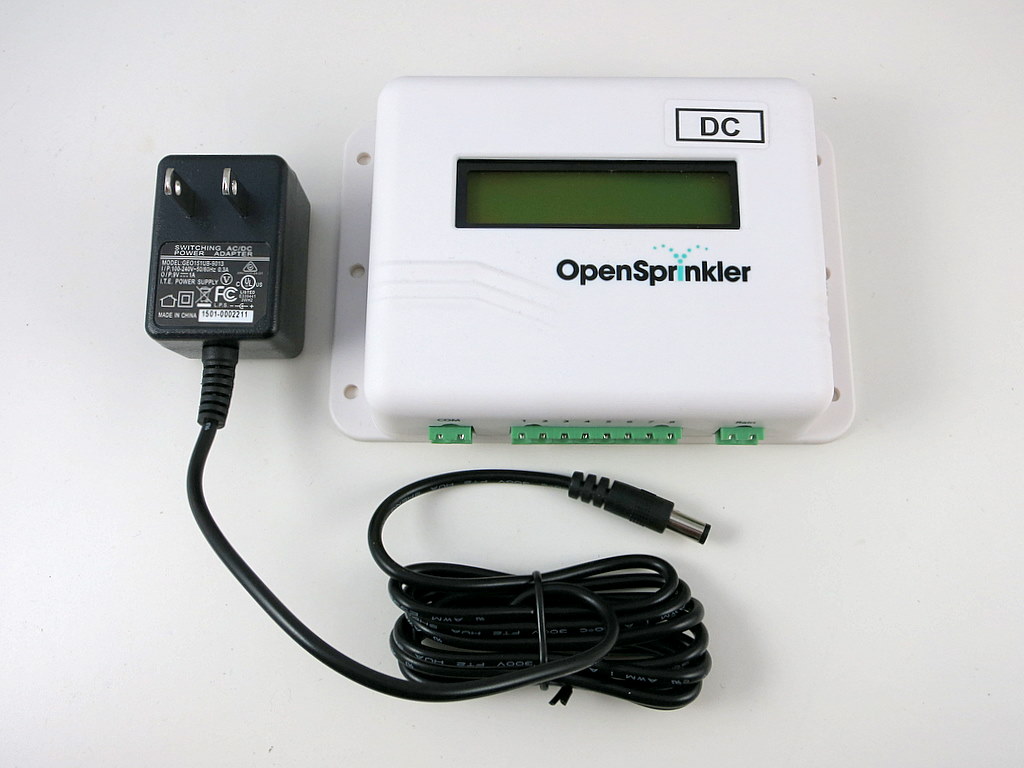
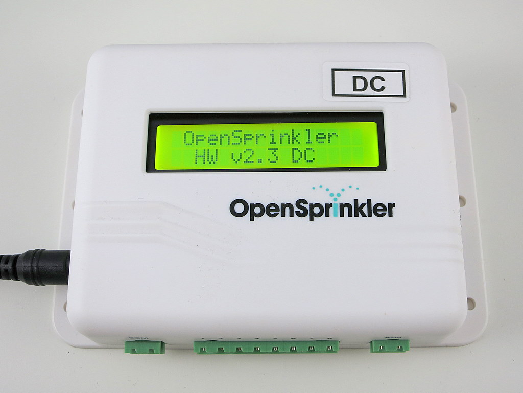
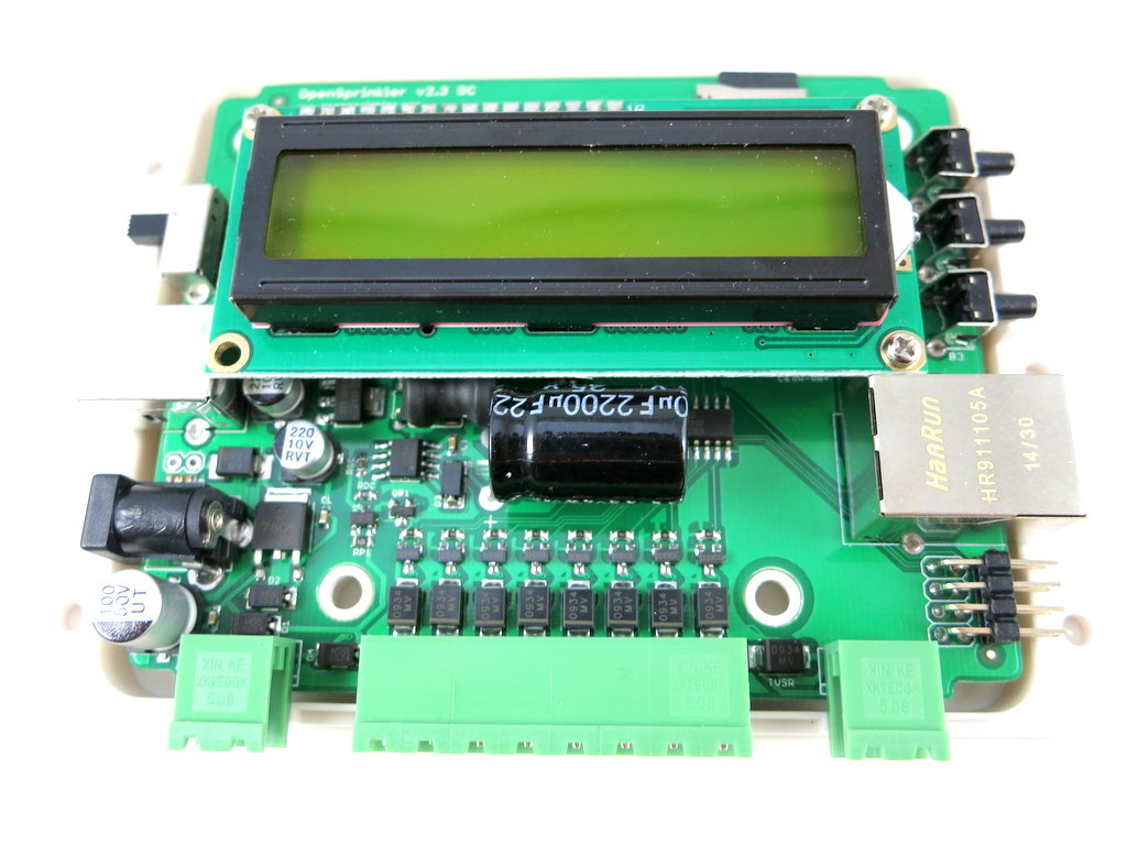
After several months of continued development, I am excited to announce the release of the first DC powered OpenSprinkler — v2.3 DC. This version uses a 9V DC universal power adapter, and is designed to work with both standard 24V AC sprinkler solenoids as well as DC (e.g. 12V DC) non-latching solenoids. Below are two pictures.
As explained in a previous blog post, the main motivation behind this is to make it easy to source the power supply for OpenSprinkler, particularly for International customers outside of US/Canada. As you know, different countries use different mains voltage standard. In US/Canada, the mains voltage is 110V AC; but in most other countries, the mains voltage is 220V to 240V AC. Because AC adapters are not regulated, you can’t directly use a 24V AC transformer designed for the US market in, say, Germany. You will either need a 220V to 110V step-down converter, or source your own 24V AC transformer. Either case, it’s a pain. On the contrary, DC transformers are much easier to source, and work universally in any country of the world. They are usually cheaper too, because their demand is higher than AC transformers. Therefore it would be ideal to use DC power supply. This is just like how your laptop adapters can work with any mains voltage in the world, so you don’t have to worry about it wherever you travel to.
Given the above benefits of DC, why in the world are sprinkler solenoids designed to work on 24V AC? To explain this, you should read my earlier blog post entitled Understanding 24V AC Sprinkler Valves. In that blog post I analyzed the electrical properties of 24V AC solenoids. They generally require a high impulse (in-rush) current to get energized (often as high as 300 to 500mA), then they will stay on with a relatively low stable (holding) current (e.g. 150 to 250mA). With AC power, the solenoids can automatically achieve this dynamic current adaptation, thanks to the solenoid coils’ electric properties (technically, the inductor’s reactance to AC). This ensures the solenoid will both turn on solidly, and remain on at relatively low power consumption and heat dissipation. The circuit design is also quite simple and straightforward.
But there is no reason why we can’t achieve the same effect with DC. Specifically, there is nothing particular about AC solenoids that they must be driven by AC — they work just fine under DC current. However, you need a more complex circuit to alternate the voltage: it needs to produce a high in-rush voltage to ensure the solenoids are solidly energized, and then reduce the voltage down to produce a relatively low (150 to 250mA) holding current. According to my calculation, 9V DC is ideal for providing the required holding current. On top of that, we just need a boost converter to generate a high in-rush voltage (18~22V) required to energize the solenoids. That’s it — this is how a DC powered OpenSprinkler works on a high level.
If you search online, you can find plenty of people using just 12V DC to power sprinkler solenoids. In my mind, it’s not the most reliable design, as 12V is barely sufficient for producing the in-rush current, and is too much for holding current. As a result, it may not successfully energize the solenoids, and it certainly will shorten the solenoids’ lifetime due to the excessive holding current. That’s why my design uses 9V DC power instead, in conjunction with a on-board boost converter. This provides the optimal holding current as well as in-rush current.
If you still have questions or confusions, hopefully the F.A.Q. below will help you answer your questions.
How is OpenSprinkler v2.3 AC different from v2.3 DC?
OpenSprinkler v2.3 AC uses 24V AC transformer (sold separately), and triacs to drive sprinkler solenoids. OpenSprinkler v2.3 DC uses 9V DC transformer (included in the package), and MOSFETs to drive solenoids. Other than these, the two use the same microcontroller (ATmega1284p) and run the same OpenSprinkler Unified Firmware.
In addition, OpenSprinkler v2.3 DC includes a universal 9V DC power adapter that can be used worldwide. In contrast, v2.3 AC version does NOT include the transformer — US/Canada customers can purchase 24V AC transformer as an optional add-on, but customers in other countries will have to source 24V AC transformers on their own.
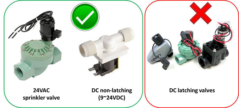
What types of solenoid valves can work with v2.3 DC?
Both standard 24V AC sprinkler solenoids as well as DC solenoids (e.g. 12V DC or 24V DC, non-latching type). Keep in mind that v2.3 DC is NOT compatible with latching solenoids.
What about pump start relay and multiple valves?
We’ve tested a few common pump start relays and they all work well with OpenSprinkler DC. We’ve also tested opening multiple valves simultaneously without any issue.
How can I decide which version to get: AC or DC?
We strongly recommend the DC version for anyone who doesn’t already have a 24V AC transformer, because the DC version includes the transformer. It’s particularly suitable for customers outside of US/Canada as there is no need to source your own power adapter any more.
Also, if you need to control DC solenoid valves, such as 12V DC solenoids, the DC version is your only choice.
On the other hand, if you need to use certain sensors that require 24V AC, such as wireless rain sensors, soil sensors, or solar sensors which require 24V AC, you are better off with the AC version as they can share the same 24V AC power supply.
Does OpenSprinkler v2.3 DC output AC voltage?
No, it does not. It uses completely DC voltage to drive AC sprinkler solenoids. To understand how it works, refer to the explanations above. Because the output voltage is DC, it can also work with DC solenoid valves (non-latching type).
What about expansion boards?
Keep in mind that the DC controller must use DC expansion boards; similarly, AC controller must use AC expansion boards. You should NOT mix and match the two, or your sprinkler solenoids won’t function properly. All DC controllers and DC expansion boards have the label [DC] attached at the front and back of the enclosure.
What’s the operating voltage range for v2.3 DC?
Although v2.3 DC comes with a 9V DC power adapter, you can power it with any voltage ranging from 5~24V DC.
Can you give me more details on how v2.3 DC works internally?
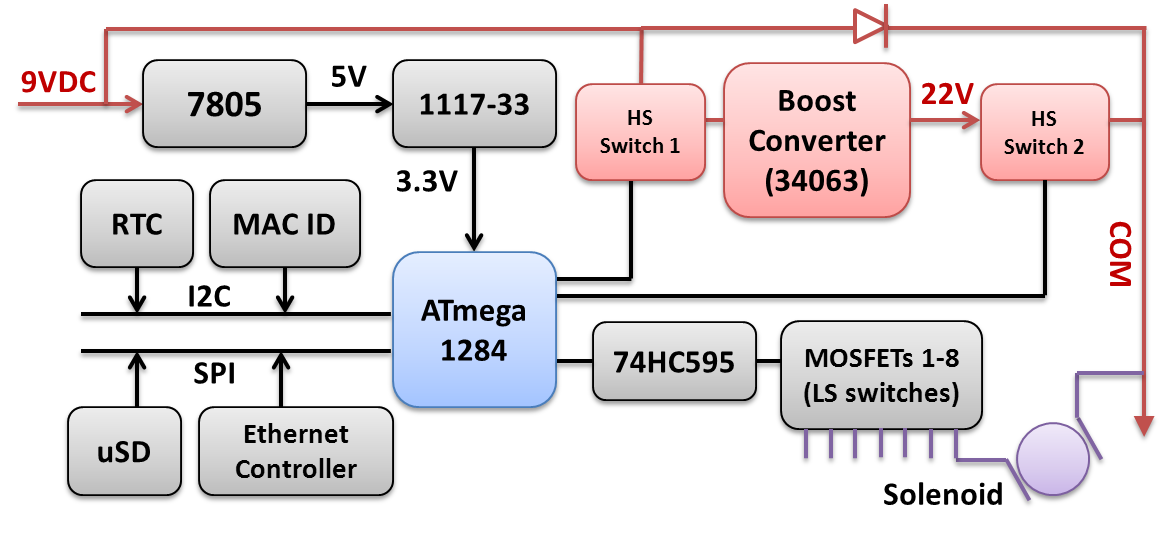
Below is a block diagram of the v2.3 DC circuit. All relevant parts are marked in red. The mcu controls two high-side switches (HS switches): it turns on switch 1 to engage the boost converter (based on MC34063), which generates 22V DC and stores that into a capacitor; it then turns off switch 1 but turns on switch 2 to dump the boosted voltage to the common (COM) wire, which provides the in-rush current. Finally it turns off switch 2 and the input 9V DC continues to provide the holding current through the diode.
The snapshot below shows the inside of the controller.