A month with no new post? That’s unacceptable. Since my last trip to Shenzhen, I actually have quite a few new ideas and projects to post about. The thing is there are so many of them that I don’t know which one to start with! Anyways, I’ve decided to put a stop to this. In this blog post, I will describe some work I did a little while back about implementing HID-class serial communication for AVR microcontrollers using the V-USB library.
Introduction
First, let me explain what I am trying to do. As you probably know, V-USB is a very useful software-only implementation of low-speed USB device for AVR microcontrollers. It adds USB functionality for almost any AVR, particularly for those without hardware USB functionality. With this, it’s possible to make a very low-cost standalone Arduino with USB port and without having to use an FTDI chip. I know there is the Arduino Leonardo, which is based on ATmega32u4, and which has hardware-based USB functionality. But mega32u4 only exists in SMT package, and it’s more expensive than mega328 after all. Besides, I am fully embracing the ‘I do it because I can’ spirit, and this is actually a great motivation for me to learn about V-USB.
What do I need the USB for? Mostly for two reasons. One is to flash a program to the microcontroller, so it needs a USB-based bootloader. For this, there is a very nice open-source project called USnoobie, which can bootload mega328 as a USBasp programmer. This way you can flash a program through the USB port directly, without using a serial cable or an external AVRISP programmer. So this is all good.
The second reason to have USB is for serial communication — the ability to transfer data (e.g. strings) in and out between the device and a host computer through the USB port. This is useful especially for debugging (i.e. printing values to a serial monitor), unfortunately this feature is missing in most V-USB projects. There are some related projects. For example, I came across the AVR-CDC project, which turns a mega328 into a CDC-class USB-serial converter. But there seem to be some limitations of using V-USB to implement CDC (i.e. violates USB standard), and also CDC-class devices require installing a driver on Windows. I would like to make a HID-class USB device which does not require driver installation. So overall I didn’t find any available resource that I can use directly.
Circuit Design and V-USB
Now I’ve explained the motivation, let’s see how to go about implementing it. The first step is to learn to use V-USB. I started with the EasyLogger project downloaded from the V-USB website. It is based on the tiny45 mcu. The program reads a sensor (e.g. temperature or light) and presents itself as a USB keyboard to print out the sensor values to a host computer. This is an excellent starting point for me because USB keyboard is a standard HID-class device, and the project is simple enough that I can easily learn and make modifications.
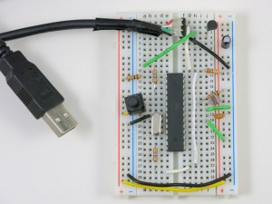
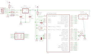
To adapt it to mega328, I first made a circuit based on USnoobie. Here is the schematic and my build of the circuit on a breadboard:
It’s a pretty standard V-USB setup. I assigned digital pin PD2 (INT0) to USB D+, pin PD7 to USB D-, and PD4 to a pushbutton. The pushbutton is used to enter bootloading mode. Specifically, if the button is pressed when the circuit is powered up, the bootloader is activated and the mcu will appear as a USBasp programmer. Different from USnoobie, I’ve decoupled this button from the D- line, so that I can use the button for general-purpose input (otherwise pressing the button will trigger the D- line). This requires changing the USnoobie code slightly to use pin PD4 for bootloading condition. Finally, I’ve also added a MCP9700 temperature sensor (you can replace it by any analog sensor such as photosensor) to analog pin ADC0 for testing later.
The next step is to modify the source code. First, change usbconfig.h to match the D+ and D- pin settings, specifically the following three macro defines:
#define USB_CFG_IOPORTNAME D /* */ #define USB_CFG_DMINUS_BIT 7 /* */ #define USB_CFG_DPLUS_BIT 2 /* */
Next, modify main.c. This step is pretty technical and tedious. It mainly involves changing register names to match mega328 (since the code was originally written for tiny45). Also, the calibrateOscillator(); function can be removed as the mega328 will be running on an external 12MHz clock.
I also modified the Makefile in order to compile and flash the code for mega328. After a few tweaks here and there, the EasyLogger started working on my mega328! It can successfully output numerical values to a text editor through the USB port. This is very encouraging. If these steps don’t make much sense, you can take a look at the code below, and give it a try yourself.
Learning HID
HID stands for Human Interface Device. It’s a USB class designed primarily for keyboard, mice, joystick, and similar human interface devices. The nice thing about HID is that it’s supported on all operating systems. For example, on Windows, the system uses built-in HID driver to handle USB requests, so no driver installation is required. This is why when you plug in a keyboard or mice, you never have to install a driver (imagine how annoying it would be if you had to!).
To implement HID, you first will need to construct a HID descriptor, which describes the number of reports, and the size, meaning, and (optionally) value range of each report. For example, these reports can be the ASCII code of the pressed key, the x and y offsets, and button presses of the mouse. There are also more general-purpose reports like a buffer of bytes. This is what I will be using to transfer bytes in and out between the device and host. To be honest, the whole USB descriptor thing was very obscure to me in the beginning. I didn’t know if there is one correct way to define it, or it can be flexible. As it turns out, Linux is pretty forgiving about it, but Windows is not. After many trials and errors, I finally settled with this HID descriptor:
PROGMEM const char usbHidReportDescriptor[USB_CFG_HID_REPORT_DESCRIPTOR_LENGTH] = { /* USB report descriptor */ 0x06, 0x00, 0xff, // USAGE_PAGE (Generic Desktop) 0x09, 0x01, // USAGE (Vendor Usage 1) 0xa1, 0x01, // COLLECTION (Application) 0x15, 0x00, // LOGICAL_MINIMUM (0) 0x26, 0xff, 0x00, // LOGICAL_MAXIMUM (255) 0x75, 0x08, // REPORT_SIZE (8) 0x95, 0x08, // REPORT_COUNT (8) 0x09, 0x00, // USAGE (Undefined) 0x82, 0x02, 0x01, // INPUT (Data,Var,Abs,Buf) 0x95, HIDSERIAL_INBUFFER_SIZE, // REPORT_COUNT (32) 0x09, 0x00, // USAGE (Undefined) 0xb2, 0x02, 0x01, // FEATURE (Data,Var,Abs,Buf) 0xc0 // END_COLLECTION };
It contains an outgoing buffer of 8 bytes (to transfer data to the host) and an incoming buffer of 32 bytes (to receive data from the host). As I said above, Linux is pretty flexible about the descriptor — you can change it in many ways and it still works. Windows, however, is very strict — if you are not careful, it will simply refuse to recognize the device.
The next step is to write functions to handle the USB requests. For transferring data out, I used the usbSetInterrupt function, which allows sending data spontaneously to the host (i.e. whenever the device has something to report). (I should mention here that I wrote the code as an Arduino library called HIDSerial. So everything gets compiled in the Arduino software. You can certainly use avr-gcc to compile the code as well). I made HIDSerial an inherited class from Arduino’s Print class, so I can make use of the many available print functions (e.g. print a string, an integer, a floating point) in the class for serial printing need, without writing extra code. For transferring data in, I implemented the usbFunctionWrite function, as described in the V-USB Document Wiki.
Now, before I can test and debug the code, I need to have some minimal host software to communicate with the device. That’s what I will be describing next.
Write Host Software using Processing
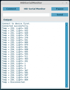
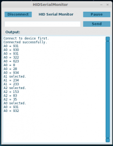
Going the HID route means the device will not appear as a standard serial COM port, so you can’t use the standard serial monitor to send and receive values. Instead, I will have to write host software myself. I can certainly do this in C or Java. But since I want to make the host software cross-platform, I have chosen to implement it in Processing, which allows me to easily export the program as standalone applications on all platforms. Long story short, to do this, I used HIDAPI library. It has all the goodies to handle communications with HID devices, such as finding a device, opening the device, reading from the device, and sending feature report to the device. Also, using the G4P library, you can easily build a GUI with buttons and text fields, and make the interface just like a standard serial monitor. Once the software is finalized, I can simply click on ‘Export Application’, and select all three platforms, and voilร , the host software is all set! Below are two screenshots of the HID serial monitor:
Source Code
The source code of this project is available for download on my GitHub repository:
- Project HID Serial on GitHub.
You can either do a git clone, or directly download the project as a zip file (see the Download .zip button on the right-hand side of the page). The folder contains circuit schematic, part list, Arduino library (HIDSerial), host software (HID serial monitor), and bootloader (optional, but recommended as it allows you to re-flash the microcontroller through USB, without any external programmer). The Arduino library consists of several starting examples, which are also demonstrated in the video above. I am sure there are bugs and issues with the code, but please feel free to leave comments and feedback below, in order for me to improve the code.
Limitations and Issues
The biggest limitation of this implementation is the data transfer speed — it’s much slower compared to a standard USB-serial converter. This will be an issue if you need to pump out data as fast as possible. But I figured that for the purpose of debugging, the transfer speed is usually not that critical. The software works pretty reliably in Linux, but I’ve found that on Windows, the host software starts to lose data after running for a while, so not all data get transferred correctly. Resetting the microcontroller and restarting the host software seem to get it back to work. I am still investigating the cause of this issue. It may still have to do with Windows being very strict with USB communication protocols. Perhaps the USB experts can take a look at the code and point me in the right direction.
Adapting the Code to Other AVRs
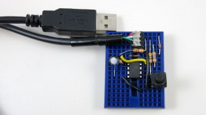
It’s relatively easy to adapt the code to other AVRs. For example, ATtiny45/85 is a popular V-USB platform, since it’s small, cheap, and has internal oscillator that can run at 16.5MHz, which meets the USB standard (so it saves a crystal and frees up two pins). By changing a couple of pin assignments in the source code, I was able to get the HID serial functions to work on tiny45. I really should do it on tiny85, since tiny45 has only 4KB flash space (even a simple demo would take more than 3.5K flash space). Here is a picture of the tiny45 breadboard build. You can even program tiny45 in the Arduino software by following the descriptions here.
Thanks for reading the post. Feedback, comments, and questions are welcome.
Hi,
Very nice work ! Thanks for sharing, I will test it soon as possible ๐
About your lost of packet after a long time (I’m not an expert at all about USB so it’s just a remark comparing codes) : on libusbdotnet examples which are displayed and we can see that the buffer is erased every polling http://libusbdotnet.sourceforge.net/V2/Index.html and your issue seems to be a typical overflowed memory so maybe it’s a way to explore …
Regards
@B@tto: thanks for the suggestion and pointer. I will check it out.
[…] HID-class USB Serial communication for AVRs using V-USB – [Link] […]
Great job! I’m very impressed. Can you please send me/post the .sch for the attiny board you created in the video.
Thanks
The attiny45 circuit is the same with the EasyLogger (http://www.obdev.at/products/vusb/easylogger.html)
Sir,
I want to control my atmega16 uController using a USB PS gamepad. Is it possible to do the same???
[…] First, the ATtiny45 (which functions as a USBtiny programmer) has been removed, partly to save space, and partly to simplify the design. Instead, the ATmega644 will be flashed with a USBasp bootloader, which allows itself to function as a USBasp programmer in bootload mode. This will take away 2KB of flash memory space, but on the plus side, it eliminates one chip, and the transfer speed of USBasp is actually noticeably faster than USBtiny. Additionally, using ATmega644 to directly handle USB tasks (thanks to the V-USB library) makes it possible to add USB serial functionality. As a result, you can do serial communication to debug the code, without any external USB serial converter. So it’s win-win-win The details can be found in my previous blog post about USB HID-class Serial Communication for AVRs. […]
[…] que vio, al parecer, se trataba de una tarea imposible sin un segundo microcontrolador, mรกs capaz. Entonces tuvo una idea : si el objetivo es sรณlo para transferir datos de un lado a otro entre un ordenador y un […]
I did something very similar but my technique allows any serial terminal to be used
http://learn.adafruit.com/trinket-fake-usb-serial
Hi Frank, thanks, I am well aware of your work on trinket fake USB serial. It’s really nice you got it working. My work was mainly driven by the goal of creating a HID-class device. It’s not standard serial, but it doesn’t require installing any driver. I’ve seen people having trouble installing libusb drivers for Windows 64-bit, that’s why I decided to go the HID route.
Hello,
Very nice work.
I am starting to use the Teensy 2.0:
http://www.pjrc.com/teensy
It has a fast usb for arduino clone:
http://www.pjrc.com/teensy/benchmark_usb_serial_receive.html
They have software their board and host pc:
http://www.pjrc.com/teensy/usb_debug_only.html
and:
http://www.pjrc.com/teensy/hid_listen.html
Best regards,
keghn
Hi keghn,
I also use have a Teensy board and you’re right it is very easy to use and pretty fast!
But it is not a “low cost” board (because it has a lot more features) to make this simple type of device.
Regards
I would like to use USB bootloader atmega 1284p processor according to your example.
Are the following changes:
# define USB_CFG_IOPORTNAME D
/ ** /
# define USB_CFG_DMINUS_BIT 7
/ ** /
# define USB_CFG_DPLUS_BIT 10 / / pin D10 – INT0, pin D2 for ATMega328
/ ** /
Thank you.
[…] with the Trinket uses HID to pass raw USB messages back and forth. This technique was created by Ray’s Hobby, we’ve added this to our tutorial […]
Hi, good job ๐
Do you know how can adapt the HID to work on atmega32?
Thanks
The code is written for atmega328, which should be very similar to atmega32. You will need to modify the mcu name/type in the Makefile, and probably the main.c as well if atmega32 uses different GPIO names with atmega328. The software is based on V-USB, which should work on most AVR mcus.
Thanks for your reply
I don’t know if the 328 is similar to 32. The number of pin is different. The link to datasheet is http://www.atmel.com/Images/doc2503.pdf, can you take a look?
Sorry, I don’t have an atmega32 chip and frankly I won’t have time to try it. Getting V-USB to work for any AVR chip is fairly simple, just define the pins you are using for D+ and D- in the source files and make a couple of changes to the Makefile to compile the code. If you encounter any trouble, google ‘v-usb atmega32’ and you should find plenty of information.
excellent work !! except some more work like this on your website!!
thanks for sharing …
good luck!
Hello Sir,
I’m fairly new to all this. I have an ATmega328 on a board and am using an ATmega8l USBasp to connect to it and upload and run programs. Apparently most of the Arduino examples are working just fine. Just the Serial ones aren’t running.
So I followed your method and downloaded all the required softwares. Next as said in the tutorial I am uploading the Hello_World code and then running the host software(which is the HID Serial Monitor). However as I try to “connect” to the USBasp, it says “could not find device”. Could you please tell me which step I’m doing wrong or atleast how and where I should use that EasyLogger code for the ATmega328, cause I’m pretty sure I haven’t done anything with it except download and extract the files. Do I need to run any file? Cause I can’t see any .exe file.
Thanks for your help in advance.
Hello!
Thank you for sharing!
I will try your project as soon, as possible at my ARCAdaptor dev board, and if everything is ok, will try to incorportate it into my source tree at git, if your are not against (leaving all referencies to your site/git, of course).
HID serial was the thing I missed so far.
that’s great job! how if i want to make hid terminal using visual basic? i had made hid terminal using visual basic, the terminal can receive data from microcontroller but cannot send data from PC to microcontroller. please help me…
Hello.
First of all, thanks for the effort you spent on this.
I tried to compile the library using Tiny cores from http://code.google.com/p/arduino-tiny/
I run into trouble with line 13 of HIDserial.h – the definition of write for string.
I replaced it to return nothing and redefined it to voin instead of size_t (fixed the HDserial.c accodringly).
It compiled, however, something seems not to be working correctly, when run using the circuit you are providing on the last image (the voltage decreased using 2 diodes, no zeners, etc).
I suspect the problem is with oscilator, which, I read somewhere, is not reliable on 3.3V operation at 16MHz for ATtiny85.
Can you, please, provide an example for ATtiny45/85 arduino sketch and some schematics?
Thanks.
Can you be more specific about ‘something seems not to be working correctly’? Does your operating system detect the device at all? Although 16.5MHz @ 3.3V is technically out of the recommended frequency scaling of ATtiny45/85, in practice there is no problem doing so (unless if you are using the device under extreme temperature conditions). Example sketches are already included in the zip file provided at the end of the post.
I will sound stupid, but I cannot provide any other explanation of the behavior.
When I only plug in the resistors and the diodes to the USB port (the same way as your picture with the ATTiny), the dmesg says something like USB device connected and than Error: Device not accepting address…
Exactly same thing happens when I try to connect the ATtiny85 with the resistors.
As I do not have logic analyzer, I am kinda lost and don’t know how to provide more information ๐
But, I made a simple code change – I put a blinking loop into the code and I can see the LED is not working – for me this could mean that the BOD jumped in or something ๐
As I said, I am lost ๐
Hi , u did a great job. actually,I have a project that I have to realise soon:
I need to receive a data that is coded in NRZL code. for that, I will use the PIC18F4550 and a usb to read the data in PC.
so please I need the source code to programm the PIC for the communication and also what u think is necessary. Thank youuu
Great job! As you said Avr-cdc violates some usb standard plus it also require drivers, but avr cdc can be used as universal usb2uart bridge so that we can communicate any MCU having uart with Pc using serial terminal. So I request you if you can make something similar like a simple usb2uart converter(using attiny/mega) with HID class and ur above cross platform software(no virtual com port). Is it possible?
It’s definitely possible (use avr-cdc as a starting point). But right now I don’t have any spare time to work on this. Plus, the HID serial work provided a great inspiration for me to learn V-USB. As for CDC serial, there are already existing resources so I feel less inspired because it’s more like a re-working of existing code. Not a good reason to dodge the work, but hope it’s understandable ๐
Hello Ray,
This is a very good work. Thank you for sharing it.
I’m wondering if this library can coexist with a bootloader (like micronucleus) on a ATtiny85 Digispark-like board. I tried to change the pins in usbconfig.h (PB3 for D- and PB4 for D+ instead of PB0 and PB2) and then to flash to the chip, but it doesn’t seem to work: nothing happened and HIDSerialMonitor don’t recognise the board. The problem is maybe the pins I used (does the library only work with PB0 and PB2?) or is maybe the VendorID and ProductID change after boot (bootloader starts with 16d0:0753, and then the program goes to 16c0:05fd). Or maybe it isn’t possible to have a bootloader and a program sharing the same USB port.
Do you think that it is possible to do? If yes, what should I do / try?
Best regards,
Luca
Hi Luca, it should be able to work with a bootloader. Because the code relies on V-USB, according to V-USB requirement, D+ must be connected to INT0 (PB2) so unfortunately you can’t change this pin; D- however, can be substituted by another pin. Does Digispark use PB3 and PB4? I had always thought it also uses V-USB internally, but perhaps I am wrong.
If this doesn’t work, an alternative is to consider using the USBasp bootloader, which is built-on V-USB. SquareWear (ATmega328) and OpenSprinkler 2.1 (ATmega644) both use USBasp bootloader, and it should be pretty easy to modify it to work with ATtiny85.
Hi, can your library run directly with arduino uno bootloader, changing boards.txt cpu_speed to 16.000.000?
No it can’t, because it uses the V-USB library, which requires specific hardware setup. If you have Arduino Uno, it already has CDC-class serial, any reason why you want to run HID-class serial on it?
Dear friend
I rode the circuit however can not burn the bootloader project so whenever I connect the circuit windows does not recognize, would have some way of recording for this bootloader ISP usnado my Arduino UNO?
I thank
To burn the bootloader you need an ISP programmer, such as USBasp, USBtinyISP, or use your Arduino to serve as an ISP programmer. The circuit will not be recognized in Windows unless if you burn the bootloader to it.
just that I can not do because to program the ATmega 328 as isp arduino IDE needs to reconhecelo as board, do not know how to burn the bootloader project for Arduino IDE, I can program it but do not know exactly how to write the right bootloader because IDE recognizes it as a Duemilanove or arduino UNO and writes these bootloaders.
Hello.
Thanks for your effort
I have a problem in HIDSerialMonitor class thatยs wrote in java, actually I wanna adjust the code to make the received data that appear on applet monitor printed only on console and remove the applet window (remove overall GUI), I were able to print the received data on console but I canยt execute the second step to remove the GUI of applet and keeps receiving and sending data
import processing.core.*;
import g4p_controls.*;
import com.codeminders.hidapi.HIDDeviceInfo;
import com.codeminders.hidapi.HIDManager;
import com.codeminders.hidapi.HIDDevice;
import java.io.IOException;
import java.util.List;
import java.util.ArrayList;
public class HIDSerialMonitor{
String serialText = new String();
static int VENDOR_ID = 0x16c0;
static int PRODUCT_ID = 0x05df;
static HIDDevice device = null;
static Boolean device_initialized = false;
public void setup() {
device_initialized = false;
}
public void draw() {
if( device != null ) {
String result = deviceRead();
if( result != null ) {
System.out.print(result);
}
}
}
public static void deviceInitialize() {
if (!device_initialized) {
device_initialized = true;
com.codeminders.hidapi.ClassPathLibraryLoader
.loadNativeHIDLibrary();
}
}
public static void deviceFindFirst() {
deviceInitialize();
HIDDeviceInfo[] infos = deviceFindAllDescriptors();
if (infos.length > 0) {
try {
System.out.println(infos[0]);
device = infos[0].open();
} catch (Exception e) {
device = null;
}
}
}
public static HIDDeviceInfo[] deviceFindAllDescriptors() {
deviceInitialize();
List devlist = new ArrayList();
try {
HIDManager hidManager = HIDManager.getInstance();
HIDDeviceInfo[] infos = hidManager.listDevices();
for (HIDDeviceInfo info : infos) {
if (info.getVendor_id() == VENDOR_ID
&& info.getProduct_id() == PRODUCT_ID) {
devlist.add(info);
}
}
} catch (Exception e) {
}
return devlist.toArray(new HIDDeviceInfo[devlist.size()]);
}
public String deviceRead() {
try {
device.disableBlocking();
byte[] data = new byte[10];
int read = device.read(data);
if (read > 0) {
String str = new String();
for(int i=0;i 32) ? 32 : charArray.length;
byte[] data = new byte[33];
data[0] = (byte)0;
int i;
for(i=0;i<size;i++) {
data[i+1]=(byte)charArray[i];
}
data[i+1]=0;
try {
System.out.println(data);
device.sendFeatureReport(data);
//delay(250);
} catch(Exception e) {
e.printStackTrace();
System.out.println("deviceWrite error");
}
}
public void handleButtonEvents(GButton button, GEvent event) {
if( event == GEvent.CLICKED ) {
if (device!=null) {
try{
device.close();
} catch (IOException ioe) {
ioe.printStackTrace();
}
device = null;
}
}
}
private void send() {
if( device != null ) {
deviceWrite("");
}
}
static public void main(String[] passedArgs) {
String[] appletArgs = new String[] { "HIDSerialMonitor" };
PApplet.main(appletArgs);
deviceFindFirst();
}
}
how to work on a temperature sensor using usnoobie with atmega328p as on chip and v-usb.please guide us and send us some link.we have a project to complete before this month.
hi
thank’s for your prject i used it but i cant run Host Software in windows we need virtual machin for use it or no if it’s possible for you please help me or if you have another program with visual stadio please email me thank’s.
Hi
Just come across your work and it looks amazing, so I decided to build it and see what it is all about. However when i plug the USB in I get a “USB device not recognised” message. All i have done is built the schematic on a breadboard and plugged the USB in. Is there something else I should have done.
In the scheme incorrectly signed numbers legs controller
The schematic is for the SMD version of ATmega328.
Hi Ray,
Thx for sharing !
To begin, I’d try to test your “EasyLogger code modified for ATmega328” code.
I’m brand new in these stuff, but I already know how to use the Arduino IDE to burn a bootloader on my Atmega328P.
Is this enough at this point to add a new Board in the text file of the arduino config file (board.txt), point to the main.hex file and “burn” the bootloader ? If yes, do I have to tweak the fuses/lock/unlock values ?
Thx !
The fuse settings are included int he files shared in the post. For ATmega328, the fuse sets the clock source to external crystal; and for ATtiny45/85, the fuse sets the clock source to internal with PLL. Other than these there is nothing particular.
Thx
At this time I’m still stuck with a “unknown device” message. I triple checked the HW part.
Did you have this type of error too ?
I have no idea how to debug…
I’m using “zener configuration” for the 3.3V limitation (http://vusb.wikidot.com/local–files/hardware/level-conversion-with-zener.gif), can it be the source of my problem ?
Any idea about how or what I have to investigate is welcome…
Regards
Hi,
same pb
I put a scope on the data lines and I see that the D+ stay close to 0V :
[img]http://www.hostingpicture.fr/upload/6a91113d8e2bf5b08364ad5391846665.png[/img]
Don’t know how to solve it !
Before uploading the HIDSerial demo, you should probably try a few demos from the V-USB website, just to make sure your circuit is built correctly.
Hi Ray,
Perseverance always pays !
I’m able to run the USNoobie bootloader now.
The source of the pb wasn’t the HW part, but the AVR programming : I came back in a much basic compilation/programming way (avrdude by command line), and the USBsap mode finally happened !!!
Thx for your answers
Regards
ERROR
$ avr-gcc -mmcu=atmega328p -I. -gdwarf-2 -DF_CPU=12000000UL -Os -o main.o main.c
usbdrv/usbdrv.h:213:24: warning: ยusbFunctionDescriptorย used but never defined
/tmp/ccTJb3rc.o: In function `usbBuildTxBlock’:
/home/kazakof/????????/bootloader/usbdrv/usbdrv.c:536: undefined reference to `usbCrc16Append’
collect2: ld returned 1 exit status
How to send the data using Python pyUSB ????
import usb.core
import usb.util
import sys
dev = usb.core.find(idVendor=0x16c0, idProduct=0x05df)
if dev is None:
sys.exit(“No found in the system”);
dev.set_configuration()
#dev.write(0x81,”\x31″,1000)
Tried so did not work(((((
[…] what he saw; seemingly, this was an impossible task without a second, more capable microcontroller. Then he had an idea: if the goal is only to transfer data back and forth between a computer and a microcontroller, why […]
[…] Auch das kleine Trinket-Board von Adafruit verwendet V-USB. Und das Digispark wohl auch (Schaltplan hier). Zusammenspiel von Processing und HID-Device mit AVR: rayshobby.net […]
Unfortunately it seems it does not work with the attiny85 (It failed every time i connected the attiny85 to my pc). It worked only when i used a usb bootloader (micronucleus) and then it loaded the hid-serial program.. So strange..
Any idea?
#include
HIDSerial serial;
//int led = 6;
unsigned char buffer[32];
void setup() {
//pinMode(led, OUTPUT);
serial.begin();
}
void loop() {
if(serial.available()) {
int size = serial.read(buffer);
if (size!=0) {
char* b2 = (char*)(buffer);
serial.println(b2);
if (b2 == “bambuk”) {
serial.println(“OK”);
}
}
}
serial.poll();
}
how to compare strings?
Hello,
I like this project very much. I was looking to see if I could use this to read a USB keyboard and convert the scan codes into ASCII for a serial output which I can connect to an older computer using only a RS232 serial port. It would seem it’s possible with your project but I’m not sure. I’m not very familiar with the HID protocol. When I found your website it looks promising and it might help with my project. It was very common to do this with PS/2 keyboards. But I have this mini-keyboard, only 6″ long, and it’s only made with USB.
thanks
Dan
This is an ad-hoc serial protocol and is different from the standard serial (i.e. TX/RX). If your device works with standard serial, you should use a USB serial converter, such as FTDI, CH340G, PL2303.
Hello! Thank you for your articles!
Unfortunately, I can’t find out one thing:
all devices act as HID keyboard or similar, so it only sends packet to host PC. Is there any way to be able to run my software that will send data to MCU, for example, for lighting active buttons, and the mcu acts also as HID keyboard so pressing button causes standard keystrokes sent to the host. May be you know how it is possible to develop?
Yes, my implementation allows data to be transferred both ways. One of the examples shows that you can type in a message in the serial monitor software to change the analog pin that the microcontroller is reading from. That’s an example of sending data from computer to microcontroller.
Ray
First off, thank you very much for the information. I am very fortunate to come across it as it’s helping me with a project of mine.
I’m new to Processing and am running into trouble when trying to compile your code. Everything appears to be related to this “HIDAPI library” you mention and declare inside your code. I was able to install the G4P library which was easy as it looks like it was made for easy integration with processing, however, this javahidapi library seems to be tricker. First off, this is what I’m assuming you’re using for a library:
https://code.google.com/p/javahidapi/
I’ve been trying to work with the hidapi-1.1.jar which is available from the website above. I’ve tried putting in in my sketchbook library location in its native format as well as extracting it in multiple ways / folder combinations but I have always gotten errors when compiling / running your code saying:
The package “com.codeminders” does not exist. You might be missing a library
Then in the status window is says:
No library found for com.codeminders.hidapi
Libraries must be installed in a folder named ‘libraries’ inside the ‘sketchbook’ folder.
One of the last things I did was throw the hidapi-1.1.jar into the processing program folder \ core \ library folder. That cleared up half the problem and allowed the program to run and compile only leaving the following messages in the compiling status window:
No library found for com.codeminders.hidapi
It will run / compile, but when I try and run either window’s executable I get “A Java Exception has occurred ”
I’m running Java 8 update 25. It makes me think there’s still something going on with the hidapi library.
Any help would be very much appreciated
Thanks
Lane
Still hoping for some help on this issue if anyone cares to weigh in ๐
Lane
Helooo..
I’m new here need more learning.
can I use this library or method to print out data from avr to usb printer?
becouse usb printer more cheaper.
please give some trick or link to the information
Thank you.
Which USB printer? Do you have a link?
Well done sir!
I’ve made my V-USB device using ATmega8535 and it works, tested using command prompt based serial monitor on windows 7. Then I trying to use your HID Serial Monitor Interface using Processing software but it keeps saying my device not found. I think that is caused of device name definition in HIDDeviceInfo.class, HIDDevice.class, or HIDManager.class at HIDAPI Library.
I’d like to use your HID Serial Monitor because it has more attractive interface than the command prompt. So how can I change that library definition so my device can run on your serial monitor sir?
Thanks for advance
Are you using the pre-compiled HID serial monitor, or are you compiling it in Processing yourself?
I tried both of those and got the same result.
Btw my firmware using non HID-class type, it is a custom-class type where I need to install drivers first, and I have done it.
Does your HID serial monitor able to handle non HID class devices? Or what are my problems here?
If you are willing to leave the AVR world, you’d find technically better solutions. Look at the PIC16F1454. It’s dirt cheap, it’s available in DIP package, and it has got a fully compliant full speed usb peripherial built-in. Compiler, IDE, USB Stack (contained in the Microchip Application Libraries) are available at microchip.com for free download. There is no need to mess around with a noncompliant low speed only solution.
That’s true, I agree. I have been using PIC18F14K50 for a while (the first version of SquareWear was developped using it). However, Microchip’s software license is not very friendly for the open-source community (see discussions here: http://dangerousprototypes.com/2011/08/30/editorial-our-friend-microchip-and-open-source/). So while they have superior products, they are not as open-minded as Atmel. Arduino does gain the advantage of popularity: there is likely an open-source library you can find for whatever component or sensor you are using. This reduces the development cycle, and makes it really easy to prototype a project. With PIC you may have to write your own library.
HI
thanks for your nice project ! i check it with your sample pc software (using Processing) it’s ok and work well!!
but when i cheked with mikroc hid terminal that i used before recived hello world! ok but when i wants to send pc from attiny45 circuit it’s not work and i didnt find any Vs.net sample to send or recive messages. if you have sample or program for c#.net or VB.net that you checked please send for me my email [email protected]
thanks
Hi
This project is really cool. I tried this but I got an error message : missing “bootloader.tool” parameter, and missing “upload.tool” parameter. Can you please help me to fix this issue. Please reply me soon.
im interested in making this with attiny85, i dont have programmer i use arduino uno to program them so can i do it that way ?
thanks.
You can use an Arduino as ISP programmer to flash a program to ATtiny85.
do you have a tutorial on how to create the processing app to connect with HID devices? thanks
I’m trying to run this code on pro mini 328p, 5V 16MHZ version. I’ve ignored only two diodes on 5V line (will try to add the as soon as I could find them). So I’ve just flashed the precompiled bootloader and it’s not recognised by windows.
Do I have to adopt frequency and recompile the bootloader? Or could this be a fuse setup issue? I didn’t change defaults at all.
If your Arduino is 16MHz, you need to recompile the code. The provided binary is assuming 12MHz.
At last, after a week googling I found you!! Thanks for this great tutorial. I’m a bit overwhelmed by different ideas and implementation out there, but your is spot on ๐
I just started with arduino, and my first objective is to work of what makes an arduino ๐ . The above schematic has both uses tx/rx and mosi/miso, my question is do I need special code to relay serial using tx/rx to another board? Or is it builtin and all I need is to connect their pin?
What I’m trying to do is like this,
[HID Main – RX/TX ] [RX/TX to MISO/MOSI – Breakout board]
For the reason that I’d like to re-use this HID enabled setup and just use another RX/TX breakout when I just needed it. Or are these even possible?
Thanks a bunch!
I think got it ๐ thanks!
Hello,
is there any C/C++ code available doing similar jobs as the HIDserial-Monotor does ?
Linux with libusb platform highly welcome. Thank You.
wally
please i the steps to do this proj 328p
The examples given are for 328p already.
Hi Ray,
Thank you very much for posting your work. I am starting to implement this in my project. I have couple of questions though.
1) In the schematic, what are the resistor values on D+ and D- lines? They are mentioned as RD+47 and RD-47. Can you suggest some specific values?
2)I am using Atmega328p. Can I use any two digital pins for D+ and D-?
Thanks
1) Both are 47 ohm. They are named RD+ and RD-, and the value is 47 (default unit is ohm).
2) D+ pin must be connected to a hardware interrupt pin (either INT0 or INT1). The default is INT0 (which is also digital D2). INT1 is less critical, but still, I would recommend you to stick with the pin assignments in the examples, or otherwise you may have to change the source code significantly.
Hi Ray,
I have figured out the connections and I am able to transfer data via USB.
There is one problem though. The HIDSerialMonitor window size on the host computer is small for thee amount of data I am trying to debug. Hence, I tried to have a look at your “Processing” code so that I would be able increase the size of the window. I have installed Processing 3.0.1 and tried to compile your code (original one without any modifications). I am getting this error ” GTextBase.stext is not visible”. I don’t have any clue what the error is (I am new to processing).
Can you please help me on this.
Sorry, the project has been so long ago that I don’t remember all the details. Before you dive in further, let me ask you this: can you not use a USB-serial chip to do data transfer the easy way? The main reason I worked on this project was to use it as a way to learn V-USB. It’s a fun learning experience. But since cheap USB-serial chips exist (e.g. CH340G) for less than 50 cents, I’ve been using these chips on all current products I have designed. This way you can use the microcontroller’s UART functions (i.e. TX/RX) pins to transfer data to a host computer, and as much data as you want. Wouldn’t this be the easiest solution for you?
I’m using Arduino as ISP for tiny45. However the hello_world example code in HIDSerial library for tiny45 shows the following compilation error:
error “USB_CFG_CLOCK_KHZ is not one of the supported non-crc-rates!
Could you please help me fix this? I’ve previously used other tiny45/85 libraries (on Arduino as ISP) without errors.
Thanks!
Cracked it! Strangely, it works on Arduino IDE 1.0.6, but not on 1.6.7.
In 1.6.7 I couldn’t find a way to set the internal clock of tiny45 to 16.5 MHz.
hi ray
tank u for every thing
can u tack a video from the begining to end of project step by step.
i’m a little amutor in electronic
hello sorry my question is so silly that compile software files “EasyLogger_m328” greetings folder …..
Hello,
I have a problem in operating the circuit.
I used a card I made ATMEGA328P-au to 20 MHz.
I compiled the code and program the chip with relative fuse programming.
USBasp does not enter the programming mode. I get no error but it seems not work.
I tried to install the bootloader usnoobie compiling and programming the chip and fuse for quartz to 20MHz. Even in this way it does not work.
Then I used the firmware precompiled usnoobie atmega328p_4k_20000000.hex
and in this way the card works and enters USBasp mode.
I do not understand what is wrong when I compile the bootloader for the new frequency. In the makefile I replace the item with 16000000 to 20000000 I question the need just that. pins d + and I d- keep the default ones.
I tried everything but not getting errors do not know what to do.
I could use the bootloader working but your can not install it.
Then I wanted to install the bootloader on a card with my other ATMEGA328P already set with the lines d + = d- = d2 and d3.
The card works very well because I made with VUSB a joystick with 6 axes and 36 buttons.
I was interested in the bootloader functionality to program the chip and the possibility of serial transmission.
Thank you
Con il tuo software un poco ho risolto.
Per entrare in modo USBasp devo premere e mantenere BTN, dare impulso di reset, rilasciare BTN e dare impulso a GND D7 facendo questo atmega328p entra in modo USBasp.
Se premo solo BTN no succede nulla.
Guardo tutto questo nel file di log sysinfo in tempo reale.
Uso Ubuntu 15.10
language error in the previous post!
With your software a while I settled .
To enter USBasp so I have to press and hold BTN , give reset pulse , release BTN and give a boost to GND D7 doing this ATMEGA328P enters USBasp way .
If I press only BTN no nothing happens .
I look at all this in the sysinfo log files in real time.
Using Ubuntu 10.15
problem solved.
For USnoobie bootloader .
I had to comment out the line
MCUSR = 0 in the main in the main.c file otherwise the micro was constantly jumping to the null vector .
So I think.
I do not understand how others can work.
int main(void)
{
/* initialize */
// MCUSR = 0;
wdt_disable(); /* main app may have enabled watchdog */
bootLoaderInit();
#ifndef NO_FLASH_WRITE
GICR = (1 << IVCE); /* enable change of interrupt vectors */
GICR = (1 << IVSEL); /* move interrupts to boot flash section */
#endif
if (bootLoaderCondition()) {
//uchar i = 0, j = 0;
initForUsbConnectivity();
for (;;) { // main loop
usbPoll();
#if BOOTLOADER_CAN_EXIT
if (requestBootLoaderExit) break;
#endif
}
}
leaveBootloader();
return 0;
}
Hello,
I have a problem when using vusb on AT328P (D + as pin 2 and d- as pin 7 ), i can no longer use PD6 as an output. (all the others pins work perfectly as output)
The command pinMode (6, OUTPUT) crash vusb.
someone has already experience this problem?
Hello
No, no problem if you use the PD6 pin as an output.
In ATMEGA328P chip I usnoobie the bootloader and runs a sample sketch using my library usbserial .
I used this card as analog joysticks with 6 to 10 -bit axes and 36 buttons I’ve used virtually all IO pins of the chip .
Watch usbconfig.h file and see if you’ve enabled USB_CFG_PULLUP_IOPORTNAME D USB_CFG_PULLUP_BIT 6
Others do not know .
Hello,
I realized it’s a library that a host software does not use the HID driver but the libusb libraries .
Practically idetiche yours.
I basically cloned your project.
I changed only some parts to be able to use the new libusb libraries .
I created a version of the host -side software in gtk + 3 for both libraries libusb 0.1 to 1.0 for libusb libraries . The 0.1 is not stable enough, numerous errors of IO and also on my laptop after a certain time lead to a USB controller block ohci – pci and all that is connected does not work.
The 1.0 are more stable.
Very few errors of IO and no block – ohci pci controller .
I’m testing a sample program on the my board atmega328-20MHz from hours
and there were only a handful of IO errors and no errors or severe block to exit the application .
Hi!
Thanks for the project.
I implemented it on Attiny85 without arduino board.I compile it in arduino SW and find the hex file from temp folder and burn using avrdude or khazama programmer to my IC.
I realize after flashing program and fuse bits,Some IC works well and windows show HID USB complaint device in device manager. But Some IC dont works.
There is no problem in IC as i checked with simple LED on/off program.It works well.
But for USB serial communication,Windows show unknown device.
I tried many times by checking fuse bits/Hw/burning sw but some Attiny85 doesn’t work for this program.
Can anybody direct me what i should do?
Hi,
Great project. am a novice into microcontrollers… and i am an organist, so i have to make a 61 key music keyboard which i have to connect to my PC ( which runs the organ software) what should i do to achieve this goal.
regards,
Alex.
Hi,
i have usbisp , i put it in the computer it takes the driver automatically and named (USBHID).
and it doesn’t work as upload and download ,please tell me what is the problem ??
thank you.
Dear Sir,
I flash ATMEGA328P with 2K & 4K hex file even circuit give error when i plug with USB “USB Cant Regco” please help what is issue. I check circuit multiple times but it not work.
THanks
Hi Ray,
First of all I really appreciate your work of this amazing tutorial, you save my several days, I follow the steps (for m328) and do some changing in config.h, and It’s WORK, But I’m facing a problem when trying to compile your Java files (*.Jar) to DLL files, since I’m more familliar with C# (in Visual Studio), would you spend your time to drop me an email about how to do it, or maybe give me any link tutorial to manage this issue. Thank you in advance and have a nice day.
Hi, I spent days trying to make this work with some generic micronucleus board + ATTiny85. It was a no go. The USB device was not appearing at all. Flashing with micronucleus or SPI, taking care of frequency did not work.
I finally found a way.
I had a hard time finding the correct way. So here are my tips to save you some time.
– The key is to use the bootloader for gemma/trinket 16Mhz by Adafruit.
– Flash the ATTiny with the aforementioned firmware, setting fuses as E:06, H:D5, L:F1
– Use old arduino software (I used 1.0.5 from adafruit, with stuff for trinket built-in), the newer ones got changes in the libs that give compilation errors.
– Install the SerialHID lib as described in the package, open a sample sketch, and put the tiny on its USB socket.
– Flash using “Trinket 16MHz” board type, and “USBTinyISP” programmer.
– That’s it, from that moment the virtual HID appeared after a few seconds, communication tested with Echo is worked in both directions.
Hi Ray
thank you a lot for this post. could you please let met know what reference is the radial capacitor in the top right corner of the protoboard ?