Feed on
Posts
Comments

At times I feel short of digital pins on the Arduino to handle multiple button inputs. Here is an easy way to use 1 analog pin to handle many input buttons. The way it works is very straightforward: use a resistor network as voltage dividers, and then let each button feed a different voltage to the analog pin. Thus by detecting the voltage we can tell which button has been pressed.
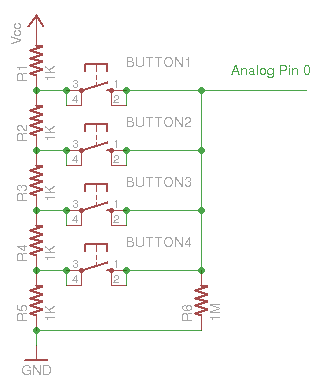
Schematic:

Download the corresponding Arduino sketch code.

As a downside, it cannot handle simultaneous button presses. To do that, one could potentially use resistors at doubly increasing resistance (1K, 2K, 4K, 8K…). Hence by checking the detected voltage, we should be able to tell which buttons are pressed simultaneously.

22 Responses to “Multiple button inputs using Arduino analog pin”

  1. imprune says:

    could this be used for 8 buttons??

    how will the program behave if more than one button is pressed at the same time?

    it looks like it will take the first one it sees
    is this correct?

    very good idea not only to save pins but to save on hardware as you can effectively daisy chain each button. i.e. for a game show buzzer system

  2. imprune says:

    can you include a picture of the wiring?

  3. Ray says:

    Yes, I believe you can extend the circuit to support 8 buttons.

    When you press two buttons together, say B1 and B2 together, it basically shorts resistor R2, so you should get a different voltage reading on the analog pin. In fact, it may happen to work out that every pair of buttons correspond to a different voltage reading. If that's the case, then you can simply set different threshold in your code to detect multiple button inputs. Need to check if this is true or not.

  4. Jermaine says:

    I'm having a hard time understanding this can you please post a image showing the wiring? Thanks

  5. […] « Multiple button inputs using Arduino analog pin Mini Maker Faire and WaterFire at Providence […]

  6. Nicolas says:

    This wont work if you press multiple buttons. try evaluating the circuit if you press the button 1 and button 2, R2 will be in parallel with the button 1, hence the current will flow through the button 1 and not through R2, so it will not mesure the button 2.

    • ray says:

      Sure, that’s a trade-off. But I am mainly using this in OpenSprinkler, where you don’t need to press multiple buttons at the same time.

    • JrBenito says:

      Hi,

      If one put btn1 in parallel to R1, btn2 in parallel to R2 and so on; Connect R5 to R6 and analog pin between R5 and R6. Then each button will short only his own resistor, this way pressing multiple buttons at once will result in different readings. i.e.:

      |-btn1-| |-btn2-| |– an1
      5v—|–R1–|—|–R2–|——|—–R3—|
      |–>>

      I don´t know if my ASCII “art” will be understand but look that if one press btn2, the volt reading on an1 will be determined by divider R1/R3, if one press both btn1 and btn2, there will be no divider. If a btn4 was added togther a R4, pressing btn1 and btn2 would result on a R4/R3 divider and pressing btn1 and btn4 would result on R2/R3 divider.

      Best regards,
      JrBenito

      • JrBenito says:

        The art was broken by spaces, lets try again

        5v—a—R1—b—R2—c—R4—d—R3—GND

        Imagine buttons in parallel with each resistor, btn1 shorts a and b, btn2 shorts b and c and btn4 shorts c and d points. Analog input is taken from point d.

        If one presses btn1 and btn4 so R1 and R4 will be shortned and voltage divider will be R2/R3. If btn 1, 2 and 4 are pressed togther than 5V would result in analog pin.

        BRs,
        Benito

      • ray says:

        Yes, I believe that will work. The tricky part is to figure out the values of R1, R2, R3, and R4. Generally the analog reading can be expressed as R4 / (R1*b1 + R2*b2 + R3*b3 + R4) where b1, b2 and b3 are binary numbers representing the button status (0 if closed and 1 if open). To distinguish between all 8 possible combinations of b1, b2, and b3, you need to choose R1, R2, R3, R4 carefully to have sufficient margins between any two combinations, in order to account for errors in resistor values and analog reading errors. I haven’t analyzed what would be the best values for R1 to R4, but generally your method should work well.

      • ray says:

        So I ran some random simulation and seems the optimal resistor values are roughly:
        R1 = 3.3K, R2 = 5.6K, R3 = 7.4K, R4 = 10K
        (up to a uniform scaling of all resistor values). In this case, among the 8 possible analog readings, the minimum difference is maximized (about 0.0464, or 0.0464*1024=47 in terms of Arduino’s analogRead function value). You will need to hard-code the 8 analog readings, so in terms of programming it’s a bit more complicated but it does detect all 8 combinations reliably.

  7. Josue says:

    nice example, i’m trying to figure out how to use it with 64 btns and multiple presses :/

    • ray says:

      You can probably use the same approach for 64 buttons (use 1% resistor for precision), but this approach does not work in general for multiple presses, because it will lead to ambiguities. For example, pressing the first and fourth buttons together in the above schematic, will produce the same voltage as pressing the second and third buttons together. That being said, it’s possible to carefully select resistor values to avoid ambiguity. This sounds like a interesting math problem to solve.

  8. Bill French says:

    I am a professor of EET at a community College in NH and teach microprocessors.
    What you want to do in order to read multiple buttons at once is use a common circuit used in many Digital to Analog Converters because that is exactly what you want here – a DAC.

    Google “R-2R network” and you will have what you need.You only need 2 values of resistors, one that has value “R” and one twice as big. In theory, you could use up to 10 buttons, since the Arduino ADC is 10 bits.

    Regards,
    Bill French

    • ray says:

      Cool, thanks for the tip. I am aware of the resistor ladder but had not thought about using them here. Good point.

    • EE enthusiats says:

      And the problem with R2R ladder in this usage is instability. Original R2R ladded refer to provide voltage through pin to the ladder, however now between them should be button, which floating (then produce nor 0 (gnd) nor 5v (vdd) for specific pin) and as that R2R ladder produce unexpected voltage. To ensure that pins not floating and in the same time to ensure voltage predictability when press multiple buttons (as described for R2R ladder) require usage of transistors or FETs. Please elaborate approach you suggesting with R2R ladder which will work as intended.

  9. Bill French says:

    I just built the R-2R circuit and it works fine, with one additional pull-up resistor.

    I used 1K for the Rs and 2.2K for the 2rRs and built 5 sections. The bottom of the chain is at ground. At the top of the chain, where the OP amp would normally be, I put a 10K pull-up resistor to +5 volts and took my output at the bottom of that 10K pull-up.

    As I grounded one or more of the 2R inputs, the voatage out moved from 2.12Volts (no inputs grounded to less than .5 volts with multiple inputs grounded. Each differnt 2R input grounded gave a different Vout and with multiple inputs grounded, the voltage dropped more.
    My 10K pull-up was arbitrary. A different value should give you s greater or lesser voltage swing.

    I agree that you need some form of pull-up at the top of the chain, whether it is an op amp or a larger resistor. No transistors or FETs are required. just a ground or no ground at the 2R inputs.
    If this is not clear, I can email you a schematic that works if you send your email address to [email protected].

    Best regards,
    Bill French

    • EE enthusiats says:

      Bill, thank you for elaboration. As to some EE enthusiast (amateur in electronic), your explanation is clear to me. Perhaps for others interest Ray may add schematic in the article.

      Thank you once again.

  10. EE enthusiats says:

    BTW, Microchip have an ANN with another approach for using multiple buttons with one input pin (Tip #7).
    http://ww1.microchip.com/downloads/en/DeviceDoc/01146B.pdf

  11. PCBPhil says:

    I used this circuit (different values) but with some programming it easily worked with 4 buttons and even works when they are pressed at the same time. 🙂

  12. Martin Thériault says:

    Hello, my two cents input to the one analog pin buttons array.

    I used a different approach to determined witch buttons was pressed. Instead of averaging the analog reading, or look for a value between a given range, I look for the lowest “absolute” difference of the (Analog reading – Analog_count (SW)) for a given button.

    The lowest difference value will alway represent the given #buttons. I don’t care about a precise resistor value or voltage variation. Voltage variation will induce the same variation accross each resistors

    EX Using the code below if the analog reading is 280

    Code:
    const int SW1 = 1024; //Expected Analog values for a given button SW: Switch
    const int SW2 = 293;
    const int SW3 = 81;
    const int SW4 = 30;
    const int NO_SW = 12;

    value = analogRead(ANALOG_PIN); // ex analog read = 280

    int T1 = abs(value-SW1); // abs(280 – 1024) = 744
    int T2 = abs(value-SW2); // abs(280 – 293) = 13….. this is the lowest value
    int T3 = abs(value-SW3); // abs(280 – 80) = 200
    int T4 = abs(value-SW4); // abs(280 – 30) = 250
    int NOSW = abs(value-NO_SW);// abs(280 – 12) = 268

    if (T1 < T2){ SW = 1;} //
    else if (T2 < T3){ SW = 2;} // This buttons was pressed
    else if (T3 <T4){ SW = 3;}
    else if (T4 < NOSW) { SW=4;}
    else {SW=0;}
    }

  13. Martin Thériault says:

    Please excuse the format. I don’t know how to change it

Leave a Reply to Bill French