Feed on
Posts
Comments

SquareWear v2 and Mini

An Open-Source Arduino-based Wearable Microcontroller


Updates


Overview

• What is SquareWear v2?
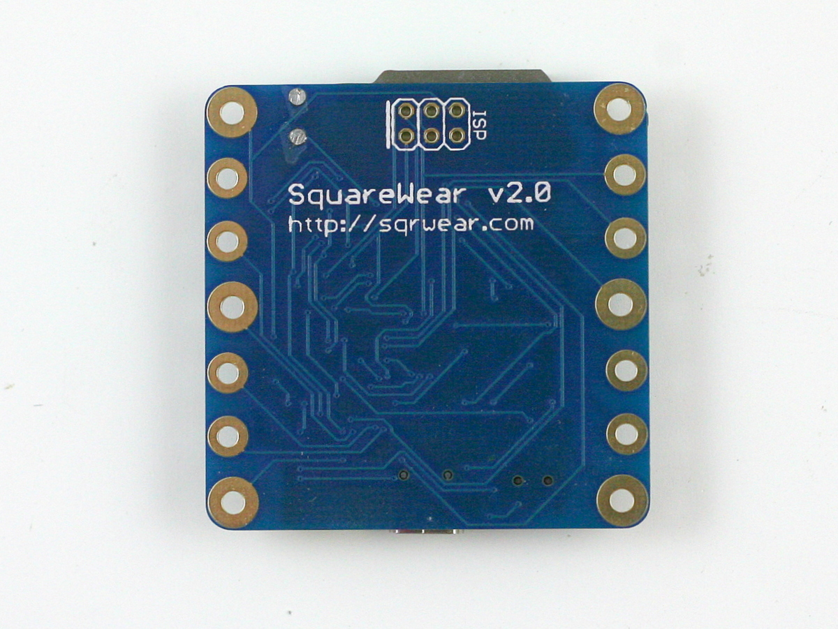
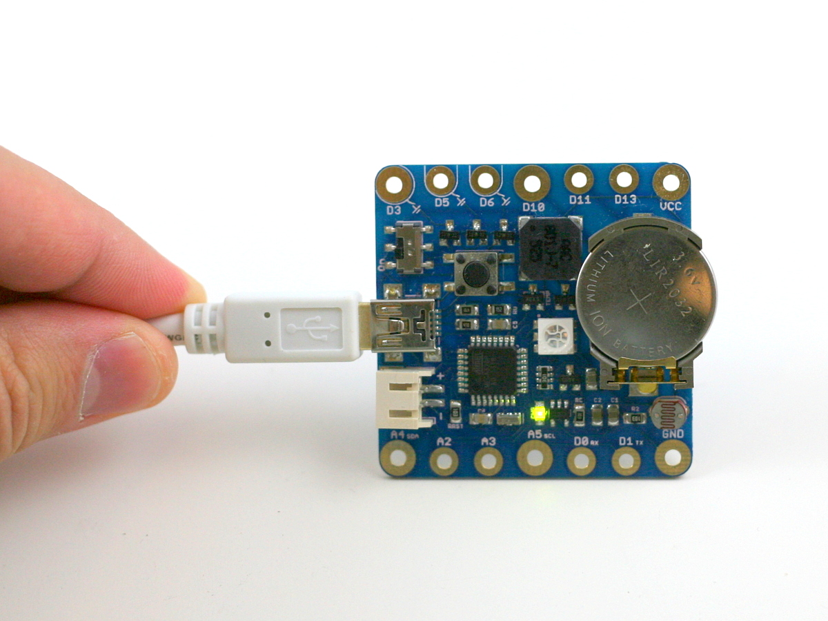
SquareWear v2 is an open-source, Arduino-based wearable microcontroller board. It is small, low-cost, and provides an all-in-one solution for wearable electronics projects. At heart it’s an Arduino running at 3.3V and 12MHz. It has large pin holes to allow conductive thread to stitch through. You can also solder wires directly, or solder snaps for quick attachment and detachment from textile. The large pins are also great for touch sensing. SqureWear v2 is packed with useful components. It has an on-board mini-USB port, which is used for programming, for charging batteries, and for serial communication. No external programmer or USB serial converter is required. It has a color LED, a general-purpose push-button, a buzzer, a light sensor, a temperature sensor, and three MOSFETs to drive high-current load. In addition, it has a built-in rechargeable lithium coin battery, so you can power your projects right away without external power supply. Every time you plug in the mini-USB cable, it charges the coin battery automatically. If you want a higher-capacity battery, you can also plug in an external lithium battery through the on-board battery jack. The on-board lithium charger can charge either the coin battery or external battery. It’s perfect for building wearable electronic projects as well as general-purpose microcontroller projects. It’s also a great platform for learning Arduino programming.

Unlike the standard Arduino, SquareWear does not have a separate USB-to-serial chip. Instead, it simulates USB functionality all in software, using the V-USB library. It has a USBasp bootloader, and can perform serial communication through USB. It can also simulate a mouse, a keyboard, or other human interface devices (see V-USB example projects). While software-based USB is not that fast, it really helps reduce the cost and size of the board by having one chip to carry out all the tasks. That’s why we can offer SquareWear v2 at a very competitive price.

IMG_2856IMG_2861IMG_2858

• What is SquareWear Mini?

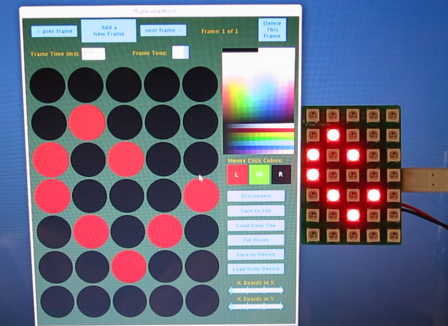
SquareWear Mini is a variant of SquareWear v2 — it has the same set of components except it doesn’t have the built-in coin battery and color LED. It is 25% smaller than SquareWear v2, and it has added an extra 16KB EEPROM. Like SquareWear v2, the Mini is a general-purpose, wearable microcontroller board, but it’s also specially designed to plug into our new chainable color LED matrix. This enables a whole new set of applications that involve color display. We also provide a cross-platform software for interactively designing pixel patterns and even an animation!

sqrwear_mini_headerviscap2

• Technical Spec

  • ATmega328 running at 3.3V, 12MHz, pre-flashed with USBasp bootloader.
  • MCP1700 3.3V / 250mA LDO linear regulator.
  • MCP73831 Lithium charging chip and charging indicator LED.
  • MCP9700 temperature sensor; 10K LDR (light sensor).
  • 8.5mm SMT buzzer; 6mm SMT tactile button.
  • 2.0mm JST connector for external lithium battery.
  • 2N7002 MOSFETs, SMT mini-USB port, and power switch.
  • 5mm color (RGB) LED (not available on Mini).
  • LIR2032 (20mm) rechargeable lithium coin battery (45mAh capacity) (not available on Mini).
  • 24LC128 I2C EEPROM (available ONLY on Mini).

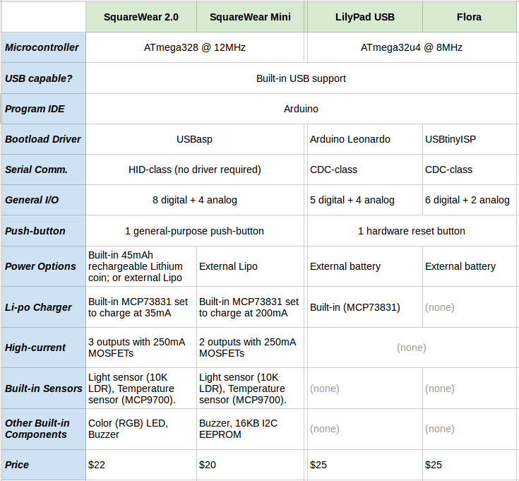
• How is SquareWear different from LilyPad Arduino USB and Adafruit’s Flora?
LilyPad Arduino USB and Adafruit’s Flora are two popular wearable electronics board based on the Arduino too. Here is a summary of the main differences:

sqrwear2_comparison

Buy SqureWear v2 from Rayshobby Shop.


(SqureWear 1.1 homepage is archived here.)

51 Responses to “SquareWear”

  1. Jake says:

    Awesome, saw the link off of Hack a Day.
    Great use of the PIC. Love the fact that it has the USB support built into the chip.
    I’ll have to think about the USB / bootloader option for my next project.

  2. Sean says:

    Hi there, just seen the video off youtube, very interested and think you’re going to sell lots of these little hotcakes. Going to order one myself. Just wondering where you sourced the LED Matrix to go with it (the one in the video)??

    Brilliant!

    • ray says:

      We manufacture the LED matrix locally. It uses WS2812B integrated color LEDs. Adafruit.com provides a lot of information about this LED, and they market it as the NeoPixel.

  3. jeff says:

    Where is the freaking windows 7 driver!?

  4. Ozzie says:

    I am having troubles using RCSwitch with the SquareWear libraries. It looks like the usbdriver is utilizing the Interrupt Vector 0 and compilation fails for multiple definitions. How would you resolve this issue?

    core.a(WInterrupts.c.o): In function `__vector_1′:
    /Applications/Arduino sqwr 2.0.app/Contents/Resources/Java/hardware/arduino/cores/arduino/WInterrupts.c:309: multiple definition of `__vector_1′
    SquareWear2/usbdrvasm.S.o:(.text+0x32): first defined here

    • ray says:

      Good question. This is because the HIDSerial library is already using INT0, so there is a conflict. Here is the workaround:
      1. You should use RCSwitch library with INT1 (pin D3) (i.e. enableReceive(1);) because INT0 is already occupied.
      2. If you don’t need HIDSerial, do not include HIDSerial.h, and it should compile.
      3. If you do need HIDSerial, go to your Arduino folder, find the following file:
      arduino-1.0.5/hardware/arduino/cores/arduino/WInterrupts.c
      then comment out all ISR(INT0_vect) functions, for example:
      /*ISR(INT0_vect) {
      if(intFunc[EXTERNAL_INT_2])
      intFunc[EXTERNAL_INT_2]();
      }*/
      This should allow the program to compile. I just recently did a similar experiment and I am pretty sure it works.

      • ray says:

        I completely forgot to mention that because pin D3 is internally wired to a MOSFET, you need to solder a wire from the Gate pin of the MOSFET and connect that to your RF receiver’s data pin. You can’t directly use the D3 pin pad because of the MOSFET in between.

      • Ozzie says:

        Thanks Ray!

        I am just transmitting for now, so I switched over to using VirtualWire library. It works like a charm! I will take your suggestion here if I ever have to receive RF.

        I have added some wonderful sleep code to increase the battery life as well.

        I have a follow-up question, though, is there a way from me to power-up/down the MCP9700, LDR, etc. just before I put the chip to sleep? If I can, it will avoid me from going out and buying stuff to put together for an ultra-low power room monitor. Thoughts?

      • ray says:

        That’s a good question. I took a look at MCP9700 datasheet, and it looks like the chip is quite efficient already, with only 6uA operating current:
        “The MCP9700/9700A and MCP9701/9701A family of low operating current of 6 ?A (typical) makes it ideal for battery-powered applications.”
        The LDR is more of a problem, because the photoresistor is a 10K type, connected to a 10K resistor in series. So under normal lighting conditions, the total resistance would be somewhere around 20K, and that incurs 3.3 / 20K = 165uA current. Ideally if you want to be able to turn it on / off you need to power it from a microcontroller pin. To do so you need to desolder the photoresistor and change the pin that’s currently tied to VCC to an IO pin.

  5. steve edwards says:

    Great platform for April Fools.

    I wrote a sketch that ‘delays’ for 3 hours (to give you a chance to hide the Square and for the victim to fall asleep) and then runs 2 tasks:

    1) Every x seconds, beep y tones, of z frequency where x, y, and z are random()ized.

    2) Every hour blast out 30 random frequency tones to make sure the victim is awake.

    Also, before each tone is played, I check to see if the light sensor is less than 2 so if the victim turns on the lights to look for it, it stops ‘beeping.’

    I hid 3 in my son’s room. He didn’t think it was so funny 🙂

  6. Michael Meissner says:

    In going through various Arduino sites, I ran across the squarewear microprocessor and the 5×7 neopixel lights. Now, you are running squarewear at 3.3v, and can power it via a rechargeable coin cell battery (on the bigger version, not the mini) or lipo battery at 3.7v. It looks nice for an integrated platform.

    One of the things I’ve seen using Adafruit neopixels, is the newer neopixels require 5v, and will not work at 3.7v power (I have an Adafruit 24 led ring like that). I believe this is due to the industry changing from WS2812 to WS2812B’s and the WS2812B’s are stricter about voltage requirements.

    I’ve read that some WS2812B’s are so called grumpy strips that require 5v signalling as well as 5v power, which makes it harder to use on 3.3v processors like your squarewear (or Teensy 3.x, Due, DigiX, 3.3v Trinket, Gemma, etc.) without using a 74AHCT125 level shifter.

    Since you manufacture the 5×7 matrix chips, and sell 3.3v processors to use them, I assume you are testing these leds to make sure they are working fine at 3.3v. Is that correct? Long term you probably need to figure out a transition scheme to 5v once the supply of the original WS2812’s run out.

    Also, I noticed you use a ATmega328 and not ATmega328P in the squarewear. I assume the 328 has 2K sram and 1K eeprom just like the 328P used in the UNO does. Is this correct? I realize the squarewear mini has an extra eeprom i2c chip, but I’m talking about the standard EEPROM, as I use the EEPROM to store some configuration information, and if I ordered a squarewear, I would want to use it.

    Besides differences in the boot loading signature, is there anything else to watch out for comparing a standard ATmega328p processor like the Uno to the ATmega328?

    Any idea how long a squarewear 2.0 would last on the coin cell battery? Obviously, it would not last long powering WS2812 leds, but I was curious how long it would last on a simple sensor, and the builtin LED.

    Thanks in advance.

    • ray says:

      1) The LED matrices we make are all tested to work with SquareWear and 3.3V. Perhaps the problem you were referring to happens when the LEDs are powered by 5V but the data signal is 3.3V. This may cause issues because 3.3V may not be recognized as a logic high. In our examples, the LEDs are powered by 3.3V and the data signal is also 3.3V, so it should be fine.
      2) The only difference between 328 and 328p is that the p version has pico-power feature which means its power consumption (in sleep mode) is lower. The signature bytes are also slightly different. All current squarewears use the p version.
      3) Both 328 and 328p have internal EEPROM (1KB). The external EEPROM on mini is mainly used to store larger data such as animation frames.
      4) The battery use depends on how much current is drawn. The battery is 45mAh so you can calculate how long it will last, given the current consumption. With a single LED, it should last for at least several hours. With LED matrix, it will be a lot shorter. That’s why I recommend reducing the LED brightness (at full brightness the LEDs are actually very bright and there is no need to leave it in full brightness).

  7. Michael Meissner says:

    Thanks. What I meant is I’ve seen various reports of various new WS2812B LEDs being stricter about voltage requirements than the older WS2812 based LEDs, and I have direct experience with one.

    I have an Adafruit 24 LED neopixel ring. It WILL NOT WORK if fed 3.7v power from a lipo battery, and 3.3v signal (from an Adafruit Gemma). I use a max brightness setting of 30. It will work if I feed it 5v power and use 3.3v signals (using Teensy 3.0). The older Adafruit 16/12 LED neopixel rings that I have work fine with 3.7v lipos. It is not a matter of the number of LEDs, since I can power 2 rings of 16 LEDs each and a Gemma with a 1200 maH lipo. But if I use my single 24 LED ring, it will not work. So, I’m wanting to be sure I know whether I have to power the LEDs via a 3.7v lipo, or 5v USB battery.

    I have read of other people for whom 3.3v signalling will not work with 5v power. And those folks must use fast level converters to get the signal to 5v. So far, I have not experienced that.

    • ray says:

      Interesting to hear that the neopixel ring doesn’t work with 3.3V. The neopixels that we sourced can all work with 3.3V, but perhaps as you said the new design has changed the power requirement. The other thing is that SquareWear is clocked at 8MHz, I wonder if that makes any difference.

      • Michael Meissner says:

        If I recall, the Adafruit neopixel library has assembler code for the various AVR chips based on the speed, and I was using the Gemma (ATtiny85 processor from Adafruit) is also 8Mhz, but it is a somewhat different processor than the 328p you use. It looks like it has separate asm code for each PORT register. However, given the Gemma can drive other neopixel rings, so the basic code does work.

        The other microprocessors that I have are all 5v, and it works fine with those.

        What interested me about squarewear is it seems made for costumes, etc. using a lipo battery, and if I wanted to use one panel of the 5×7, the mini 2.0 has the snaps on the back of it to drive the panel. I’ve given up on the ATtiny85 processors, as they have too many restrictions compared to the bigger 328p, 32u4, and ARM processors.

      • ray says:

        Indeed SquareWear is designed for wearable electronics, and SquareWear Mini is a smaller version that’s specially designed to plug into the 5×7 panel. I’ve adopted mega328p instead of tiny85 because frankly the price difference between the two is less than a dollar but mega328p is much more capable.

      • Michael Meissner says:

        I recently picked up the Squarewear 2.0 from Microcenter (in Cambridge, MA). In the normal setup for Squarewear (using D10 as the data pin, VCC/ground to the neopixel data pins), I hooked up the 24 LED ring from Adafruit that has been problematical with other 3.3v microprocessors (Gemma, Teensy 3.0/3.1), and it works fine. Why it works fine for squarewear and not the other processors, I don’t know. I suspect it is due to needing to hook the power pin of the neopixels to the VIN pin (3.7v or 5v) and not the 3.3v rail. On the squarewear, you don’t have a separate pin for this, but your 3.3v pin can provide high amps than the other processors.
        I thought I would mention that it does work in the normal setup, even with a ‘grumpy’ LED ring that has been problematical on other 3.3v processors.

      • ray says:

        Honestly I am also not sure. The LED strips and matrices that we carry ourselves (http://rayshobby.net/cart/accessories/acc-leds) have actually worked fine with most 3.3V boards that I’ve tested. It’s possible that the difference is due to the current capability on the 3.3V pin, as you said.

      • Michael Meissner says:

        FWIW, I recently picked up a squarewear mini/LED matrix as well as the squarewear 2.0. If I run the rainbow demo and power the mini ONLY with the USB power from my laptop or from a 5v/1a wall wart only the first 5 LEDs get lit, and they don’t do the proper colors (a few are always red, sometimes the other are pure white or other colors). If I plug a lipo battery into the JST connector, then it works perfectly when I have USB power and when I don’t. Given I intend to always run the squaremini in wearables, it isn’t a hardship to always have a lipo battery connected.

        In looking at the squarewear 2.0 (with the white battery holder) that I bought at the Cambridge Microcenter, I don’t see the markings on PCB next to the D3 pin to indicate that it is connected to a MOSFET, and it acts like a normal pin (i.e. connecting LED power to D3 and ground to GND, the light blinks normally). D5/D6 are connect to MOSFETs (where I need to connect the positive wire to VCC and the negative wire to the MOSFET pin). Did you recently change the squarewear 2.0 to eliminate pin D3 as being a MOSFET? If you were going to eliminate a MOSFET pin, I would have preferred eliminating D6. It means if I move stuff back and forth between the 2.0 and mini, I can only use D5 as a MOSFET pin (I only need one MOSFET pin).

      • ray says:

        1) As explained in the user manual (page 3): http://rayshobby.net/software/sqrwear2_manual.pdf, the battery should be plugged in at all times. Technically, this is because on SquareWear USB power is only meant to charge the battery and is not directly connected to the linear regulator or VCC. So if you try to power SquareWear from USB without battery, it can only provide a small amount of current.

        You said you intend to run Mini in wearables, how do you connect a USB cable to wearables? Isn’t battery more convenient?

        2) Sorry about the confusion of pin D3. You are right that it has been updated very recently, to remove MOSFET on D3. The reason is that many users want to use D3 as interrupt (INT1), and having it connected to MOSFET will not allow it to function as INT1. Therefore the MOSFET has been removed from D3 in the latest version.

  8. Gary says:

    Really fascinating and insightful ideas. Bookmarked . Thanks for the amazing read.

  9. Rachel says:

    Hey!!
    I’m working on a wearable project with this but I’m having a small problem – I can’t figure out how to download the FlipbookHost. It’s probably due to my lack of knowledge of how GitHub works because I’m a beginner, so I apologize in advance. Could you help walk me through it?

  10. Rahman says:

    Hi, I’m working on a wearable project using the SIM900A GSM Module. However, I’m having errors compiling the code and the error i get is; “error: ‘XMIT_START_ADJUSTMENT’ was not declared in this scope”

    Upon further research, I suspect it’s because Squarewear V2.2 is at 12MHZ and the Softwareserial of the GSM module supports only 20, 16 and 8MHz processors.

    Let me know if my suspicions are correct? And if there is a workaround?

    Thanks!

  11. Krishna Mohan Bandi says:

    Great work, nice demo of the device with practical examples, applications.

  12. Lily says:

    Hello, I am a design student working on a smart textiles project where I am using Nitinol (Shape memory alloy) powered electronically using arduino. I am extremely new to this side of design and was wondering if anyone has experience with shape memory and could help with some of the following:

    – What kind of arduino code/programming would I need to control the Nitinol? Is this available anywhere or must I write my own.
    – Will the MOSFET outputs provide enough voltage to power the Nitinol if I combine them?

    Thanks!

    • ray says:

      To control Nitinol is more about connecting the hardware. Other than that it’s just a matter of setting a pin high / low to activate / deactivate the wire. The voltage depends on your power source — the MOSFETs can supply high current required to activate Nitinol. What’s the current requirement of it?

      • Lily says:

        Thanks for getting back to me.

        I am aiming to connect 6 of the flexion wires in a series and I have figured out that the total voltage needed for that is 10.8v @ 500mA. And I have an external 11.1 v LiPo battery to use as well. Will the MOSFETS support this?

      • ray says:

        500mA may be stretching the limit for one MOSFET pin. But you can combine two MOSFET pins together to provide twice as much current. Alternatively, you can connect an external MOSFET that can sustain at least 500mA.

  13. Builder says:

    Hi! I am planning on buying your amazing product! I am running into a an issue though. I need 16 digital/analog pins. Square wear only has 12. Do you have a work around>=?

    • ray says:

      Among the 16, how many do you need as digital, and how many as analog? Note that Arduino only has 6 analog pins. Among them, SquareWear uses A0 and A1 for the built-in light and temperature sensors. There are a few additional pins that are available from the ISP pin header (the 2×3 pin header). I think in the end it may be able to provide the 16 pins you need.

    • Anonymous says:

      About 4 analog and the rest digital

      • ray says:

        In that case you may consider SquareWear 2.3, which I blogged about here:
        http://rayshobby.net/sneak-peak-preview-of-squarewear-2-3/
        we do have some SquareWear 2.3 in stock (it hasn’t been officially announced, but we’ve been using these at university workshops). It should have sufficient number of pins to meet your need (note the additional pin out on the right edge of the board).

  14. zack987 says:

    Is the wifi version out already? The one shown here: https://www.youtube.com/watch?v=xXxnddZikco

    • ray says:

      I am doing the last refinement, as there are a couple of issues with the current pin assignment. But I expect to release the final version in a few weeks of time.

  15. WaterClosetBiker says:

    Hi,

    Just purchased SqrWare 2.2 and also got a door sensor and a small vibration sensor. I have not worked with ardunio or SqrWare before but want to use to turn on the buzzer and light when the door opens. Wife is always forgetting her phone and keys and want to use a mental reminder.

    Which holes should I use to connect the door sensor or vibration sensor? The event will be binary (Open/Close or Vibration/No Vibration.

    Thank you for your help or pointing me in the right direction.

  16. Callam says:

    Hi,

    I have just received a SquareWear 2.0 from Coolcomponents UK and I can’t get it working with Mac OS. I am using the arduino file that is included in the PDF file and I have held the button down while turning on and I still get the error below:
    “avrdude: error: could not find USB device “USBasp” with vid=0x16c0 pid=0x5dc”

    Can you advise what to do? I need this for a university project urgently!

    Thank you!

    • ray says:

      Here are my suggestions:
      1) slide on the power switch, does the default demo work? The default demo blinks the LED and you can click the button to navigate to the next demo. If the default demo doesn’t work, most likely the battery has drained. Just plug in a miniUSB cable, charge for about 30 minutes, and try again.
      2) If the default demo work, the next step is to enter bootloader. As you’ve already know, the procedure is:
      – Turn off power switch, plug in miniUSB cable. Then press and hold the button while turning the switch back on.
      – Release the button in 1-2 seconds (after the switch is turned back on). This is important as holding the button too long will cause the operating system to think the USB is malfunctioning.
      – The default demo should stop, indicating the device is in bootloading mode. Try to upload a program in Arduino and see if it works.

      • Callam says:

        Demo mode is all good! Still the same error, even following those instructions. I am using OSX El-Capitan if that would cause a difference?

        Any other ways of combatting this issue? I am quite new to Arduino you see.

      • ray says:

        I also have El Capitan. Just tried and there is no issue. Here are my suggestions:
        – As I said, once you are in bootloader mode, the demo should NOT run. If you see LED blinking or whatever, it means it’s not in bootloader mode, and you need to follow the procedure to enter bootloader mode.
        – Assuming SquareWear is in bootloader mode, go to OSX’s Utilities -> System Information -> USB, do you see a device named USBasp? Click on it and this is what mine shows:
        Product ID: 0x05dc
        Vendor ID: 0x16c0
        Version: 1.02
        Speed: Up to 1.5 Mb/sec
        Manufacturer: http://www.fischl.de
        Location ID: 0x14100000 / 15
        Current Available (mA): 1000
        Extra Operating Current (mA): 0
        – If this still doesn’t work, perhaps try a different USB cable, USB port.

      • Callam says:

        How embarrassing! It was the cable! Oddly was suppling charging power but no data! Thank you for your help, I may call on you at some point again!

  17. Marcwolf says:

    Be really great if you put the actual dimensions of the unit in the article. For those looking at embedding technologies it can be very difficult when judging down to the millimeter.

  18. Marcel Maatman says:

    I saw your youtube video with the SquareWear Mini and the chainable led matrix
    Looks very nice!
    I wonder if it is possible to integrate this with a DS3231 high capacity clock, so that it results in a 5×7 led clock.
    Sadly, I am not familiar with electronics…………
    But I have made a working 5×7 led clock in Excel with vba
    I will send the excel via [email protected].

    I hope you will manage to create such a clock, and if so, i would like to have one!
    Thanks
    Marcel

    • ray says:

      Yes it’s possible. DS3231 uses I2C and you can connect it to pins A4 and A5 on SquareWear Mini, which are the I2C pins.

Leave a Reply