It has been a while since I updated my blog. Things have been quite crazy the past few months, but now I am back alive writing more blogs sparingly.
The first thing I want to share about is an update to my previous post that talked about how to control the Orbit 62035 valve. There have been a couple of missing pieces there which I would like to clarify. First, I found that a MOSFET cannot reliably control that valve. I am not sure why, but it may have to do with the on-state drain to source resistance. But using a MPSA14 (NPN darlington) works, and it requires a base current limiting resistor, so I’ve updated the schematic as below. Second, I was reminded that two kickback protecting diodes are needed to protect the transistor from the inductive current from the solenoid, so those are also added. These are the two main changes. The circuit below has been tested to work. Feel feel to leave comments.
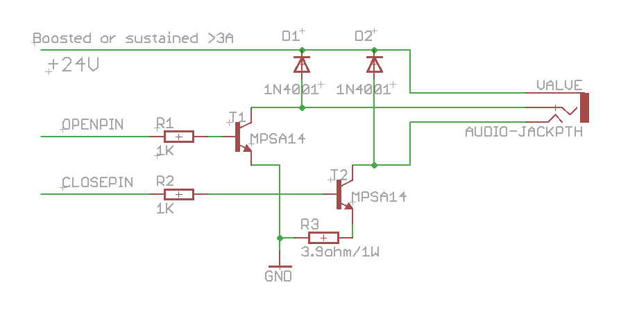
- Eagle schematic can be downloaded from here.

Hi Ray,
Thanks for this information. Couple of related questions, if you don't mind:
1. Why T1 does not have an R3-equivalent resistor connected between emitter and ground like T2 has?
2. I am thinking about trying an ULN2803A Darlington array as a substitute for the control circuit above:
http://www.sparkfun.com/products/312
Comparing the ULN2803A and MPSA14 specs I see that continuous collector current is .5A for each transistor pair in the ULN2803A versus 1.2A for the MPSA14. If the lower current rating for the Darlingtons in the array is a problem one can always connect 2 or more in parallel.
Given the price of the ULN2803A, they seem like a good option, especially since you'd end up with less components (the clamp diodes and base resistors, for example, are included in the ULN2803A).
Any reason you see why an ULN2803A would not be a good replacement for the control circuit?
Cheers!
Sorry, I should have read your initial post on this topic first — regarding (1) in my comment above I now see that you could not get the valve to close without an R3 resistor, but that to get the valve to open an R3-equivalent resistor is not needed. That explains why your control circuit does not have an R3-equivalent for T1.
Cheers!
@eloy: yes, that's correct, the closing coil seems to require an additional power resistor in order to close properly. If you measure the resistance of the opening coil and the closing coil, they are different. I don't quite understand why (perhaps because the closing coil requires more inductive load). It's ok if you have the resistor shared by both coils — the opening coil should still function properly.
As to your second question, I've actually tried ULN2803A before and it didn't work. The main reason is that it doesn't support a large current. I didn't try connecting several of them in parallel, that could work. I figured that using MPSA14 is simpler and much cheaper, so I settled with it.
@eloy: by the way, the impulse current is more important than the continuous current, as the solenoid is activated/deactivated in an instant of time. So you might need to check the impulse current limit of ULN2803. Even considering price, I think MPSA14 may still be a better option: it only costs a few cents such as on mouser.com.
Great; thanks for the feedback, Ray. I'll explore both possibilities (ULN2803 an MPSA14). I am also thinking about trying the AVR's PWM for the voltage booster, per the link you shared in one of your comments here. If anything that'll be a nice learning experience 🙂
Cheers!
Ray, loved the post and built myself a shield to control three of the 62035 valves! Take a look:
http://www.jaycollett.com/2011/05/a-new-way-to-control-water/
@Jay: Your shield looks great! I am glad that my blog was helpful for you.
@Ray, the shield I built is having a bit of an issue with some valves (I've tested 7 and 2 were like this). It works fine with some but refuses to close others. At first I thought they were "blown" but the Orbit controller will open and close them fine. I thought that the 3.9ohm resistor might not be enough for these valves so I bumped it up to 4.7ohm hoping it would allow the coil to build up enough magnetic force but still nothing. Any ideas on what may be happening? Did you measure the resistance on the controller after you took one of the resistors out of the circuit? Any insight is much appreciated!
@Jay. I've never encountered this problem. I have two of these valves and they both work fine with the circuit. I guess my 'sample' size is too small. Here is what I suggest: first, make sure no component is burnt (for example, MPSA14 might get burnt if too much current flow though it, but with the current limiting resistor this shouldn't happen). Second, try to bypass MPSA14 and apply the boosted +24v directly, for example, by shorting the collector and emitter of MPSA14. If the valve can successfully open or close, the issue must be in MPSA14 (for example, some MPSA14 has lower maximum pulse current than others). If the valve cannot close properly, the issue must be in the boosted +24v or the 3.9ohm resistor.
Let me know what you find in the end.
Btw, some side thought while looking at your circuit: the VIN pin of the LT1303 should actually be connected to the vin pin of the Arduino. The reason is that the booster can draw a large amount of current when charging the capacitor, and if the supply is from the +5V pin of the Arduino, that may cause the Arduino to reset and get things messed up. By connecting it to the vin pin, the current will be drawn directly from your power source, and hence will not cause Arduino's regulating circuit to fail.
I've actually encountered this problem in the past. I should have posted the issue in my blog.
Ray, thanks for catching that, I hadn't paid any attention to that in my design, I've updated it and will make a mental note of that for future shields! I found a thread where a gentlemen had gotten the specs for the valves from Orbit, 13V, 22ms pulse and 1 to 1.5 amp current max. I adjusted my shield to these specs and the silly valve still didn't fire so I'm at a loss. I mean it works fine with the factory controller and opens with my shield but won't close. I've tested 7 other valves and they all work just fine. Here's the thread….
http://forums.x10.com/index.php?action=printpage;topic=17620.0
Ray, after troubleshooting more, it appears that the transistors are not allowing enough current to flow through the coil, even without a resistor between it and ground. I'm measuring between 300ma and 500ma when the transistor is saturated. I've tested with new transistors, etc..this explains why the valves will open but not close. Any ideas why I'm not seeing a greater current through the transistors?
@Jay: you may want to check the specification of your MPSA14. I think some manufacturers make it with lower maximum collector current (for example, some version may have 800mA while others have 1.2A)
[…] Modify the circuit to control the Orbit 62035 valve. […]
Hello may I quote some of the content here in this post if I reference you with a link back to your site?
Yes, you are welcome to quote the content here as long as you reference my site.
I found that using the same voltage reversing scheme as the 2-wire Orbit 91592 worked on this valve as well across the 4 ohm coil (pins 1-2) and leaving pin 3 open. Perhaps they wanted some reverse-compatibility? Great info here, Jmayes
That’s a very interesting discovery. That would make the same circuit to work with this valve too. It’s a mystery to me why the second coil has a smaller resistance and requires an external resistor. But in any case, the single coil valve is more common and can be found in other brands.
Upon further investigation I found that using both coils in series (pin 2 & 3) works even better and allows reliable operation down to 12V. I came up with a very simple 2 cap design that allows these valves to be operated via 2 relays off my HA system, the relays can be sub’d with NPN/PNP transistors if you like. It also is fail safe in that if a relay or switch is left on there will be only about 1ma of current that continues to flow so the coil will not burn up, in fact you can sub the two sets of contacts for a SPDT switch or relay for single line on/off. The coil only gets the discharge current of one cap then current flow all but stops (just the 10k series resistor creates continued current).
http://jmayes.com/Orbit_Valve_Circuit1.gif
Your’e welcome to post it here if you like,
Hope this helps someone,
Jmayes
Well, I spoke out of turn saying the 3-wire valve will operate in 2-wire mode, while I get a good loud click on the bench from reversing the voltage on the 4 ohm winding it DOES NOT stop the water flow. Sorry to post before I actually put water to it. I am puzzled as to what is going on inside as I can only get a click once for each polarity, I must use the reverse polarity to get it to click again, just like it was turning on and off but under pressure the water stays flowing both ways. When I tried the valves in 3-wire mode they work fine.
On the brighter side the simple circuit I came up with WILL WORK for the 2-wire (newer) valves.
Cheers,
J
[…] and detailed blog posts that describe how the valve works: How to control Orbit 62035 valve and Update on How to control Orbit 62035 valve. The comments in Ray’s blog posts also contain some good […]
any ideas on a circuit or mod that will let me use the newer style 2 wire orbit valves, or even standard 24v sprinkler valves with my orbit 62032 timer (which uses the 62035 3 wire valves)?
getting impossible to find the valves for this timer any more
1) please check my earlier post at: http://rayshobby.net/blog/?p=18
2) there is no way to control 24VAC sprinkler valves using only AA batteries. 24VAC sprinkler valves draw a significant amount of power that way exceed the capacity of batteries.
I currently have 3 timers, and only 1 (out of 8 )working valve.
I was actually thinking of an externally powered circuit (that plugs into the 4 outputs of an orbit timer) that has the needed relays to control the actual external 24v valves (or even the current version of orbit hose valves).
Valve croaks? no problem. Just go to Home Depot/Lowes, etc to pick up another industry standard valve. or the current orbit 2 wire watering valves for their current timers.
It depends on what type of valves you are using. If it’s the battery-power type, you have to be very careful running external 24V power on them, because these valves are designed to only work with a pulse, so you need to make sure you never apply 24V power on them more than a couple hundred milliseconds, otherwise you may end up damaging the valve.