Feed on
Posts
Comments

Continuing from Part 1, this is the second post about how I reverse engineered a few off-the-shelf wireless temperature, humidity, and rain sensors, and used an Arduino to listen to and decode the sensor data. Update: RPi is also supported now! Check the provided programs at the end of this post.

Wireless Humidity / Temperature Sensor

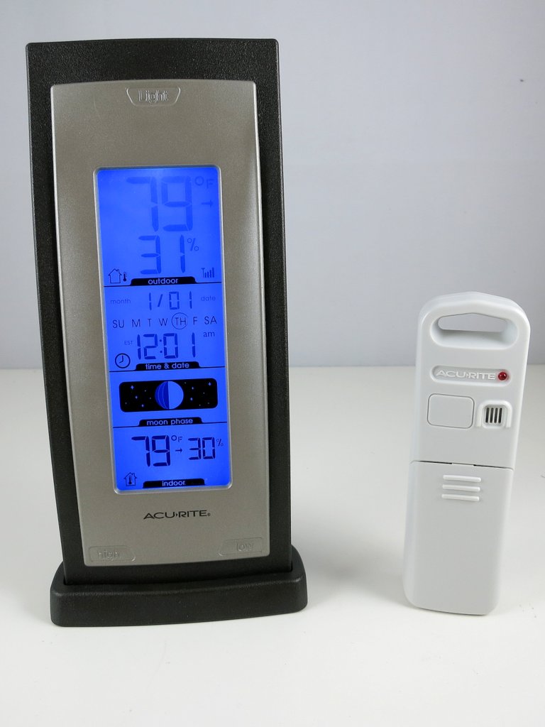
Raw Waveform. The second sensor to tackle is the Acu-Rite 00592W3 humidity / temperature sensor. This one transmits not only temperature but also humidity values. The display unit is a lot larger and looks cooler than the previous (temperature-only) one. Cool, time to get hands dirty. Following the same procedure as before, pop in the battery, power on the RF sniffing circuit, and launch the Audacity recording software, I got a waveform like the one shown on the right image below.

IMG_0053humidity_sensor_waveform

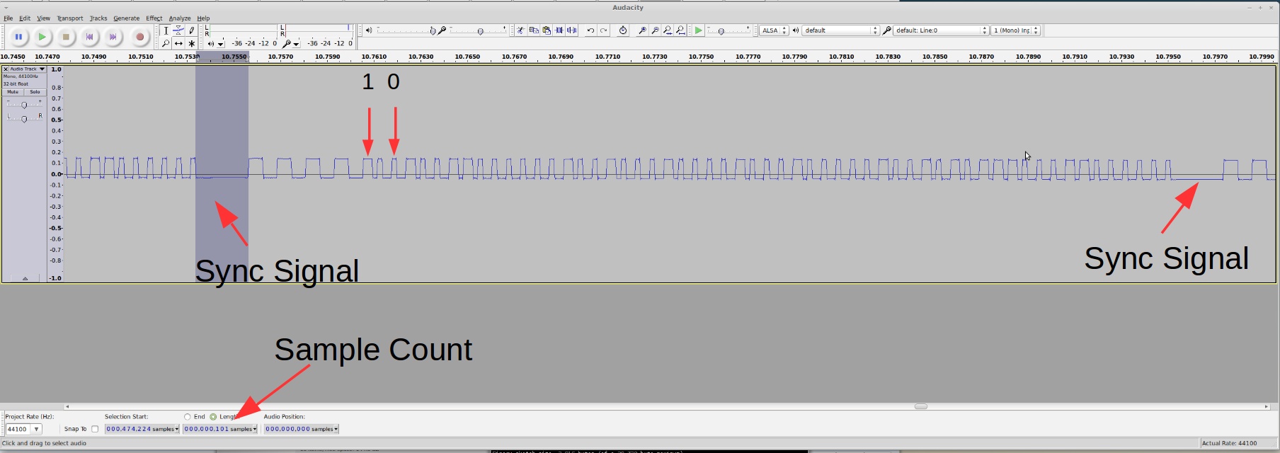
This looks a whole lot longer than before. But the patterns are still quite clear:

  • Each transmission consists of 3 repetitions of the same signal.
  • Every two repetitions are separated by a sync signal defined as a constant low of 2.25ms (about 100 samples @ 44.1kHz sample rate). This is followed by 4 squarewaves of roughly 1.2ms wavelength.
  • The bit patterns are also clear as there are only two types of patterns: logic 1 is defined by a constant high of 400us followed by a constant low of 225us; and logic 0 is defined by a constant high of 250us followed by a constant low of 400us.

Given the timing data, I quickly modified the Arduino program to convert this signal into bits. The only changes are how the sync signal is detected, and how the bit 1 and 0’s are defined.

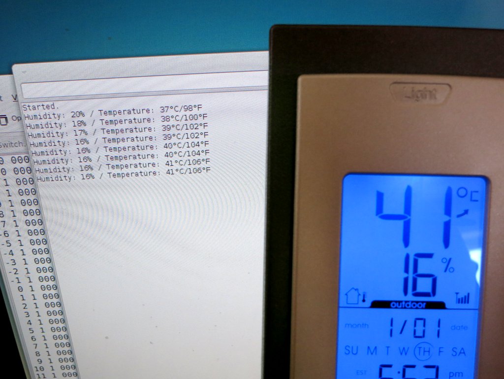
Collect and Analyze Data. I collected a few groups of data under different humidity and temperature conditions, and recorded the reference values shown on th

e display unit. Given my experience with the first temperature sensor, I set the display unit to show temperature in Celsius, to save myself the trouble of doing the conversion. Here is a selected list of the data:

10010011 00000010 01000100 00100010 00001001 10111110 11000010 (21°C/34%)
10010011 00000010 01000100 00100010 00001001 11000101 11001001 (22°C/34%)
10010011 00000010 01000100 10100011 00001001 11011000 01011101 (24°C/35%)
10010011 00000010 01000100 00100010 00001001 01100101 01101001 (25°C/34%)
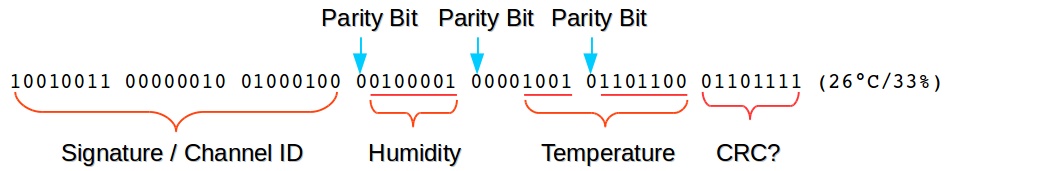
10010011 00000010 01000100 00100001 00001001 01101100 01101111 (26°C/33%)
10010011 00000010 01000100 10100000 00001001 11110011 01110101 (26°C/32%)
10010011 00000010 01000100 10100000 00001001 11111001 01111011 (27°C/32%)
10010011 00000010 01000100 10011111 00001010 10000001 00000011 (28°C/31%)
10010011 00000010 01000100 00011110 00001010 10010011 10010100 (29°C/30%)
10010011 00000010 01000100 00010100 00001010 11001001 11000000 (35°C/20%)
10010011 00000010 01000100 10010000 00001010 11010111 01001010 (36°C/16%)

Again, I grouped the data into bits of 8 to make it easy to see the byte values. The first three bytes are the same. Those are probably the signature / channel ID; the fourth byte is clearly correlated with the humidity — if you pick two lines with the same humidity value, the fourth byte is always the same. On close examination, the lowest 7 bits of that byte converts exactly to the decimal value of the humidity. To make it clear, I picked out the fourth byte, and wrote them down together with the reference humidity below:
0 0100010 (34%)
0 0100010 (34%)
1 0100011 (35%)
0 0100010 (34%)
0 0100001 (33%)
1 0100000 (32%)
1 0100000 (32%)
1 0011111 (31%)
0 0011110 (30%)
0 0010100 (20%)
1 0010000 (16%)

Aha, one puzzle is now solved. Not sure what the leading bit is (this will be revealed later), but we can move on to the next puzzle — temperature. Clearly the temperature has to do with only the last three bytes. So let me re-list them below with the reference temperature:
00001001 10111110 11000010 (21°C)
00001001 11000101 11001001 (22°C)
00001001 11011000 01011101 (24°C)
00001001 01100101 01101001 (25°C)
00001001 01101100 01101111 (26°C)
00001001 11110011 01110101 (26°C)
00001001 11111001 01111011 (27°C)
00001010 10000001 00000011 (28°C)
00001010 10010011 10010100 (29°C)
00001010 11001001 11000000 (35°C)
00001010 11010111 01001010 (36°C)

Because the data was recorded as the temperature went up, the first byte is clearly showing the right trend: it goes up as the temperature rises. These are probably the most significant 4 bits. The next byte is not very clear at all: sometimes it goes up, sometimes it goes down. What’s happening here? The last byte is even more elusive: but given my experience with the first temperature sensor, this is probably some sort of error checking code, so let me put it aside for now.

To figure out what’s happening with the second byte, I needed more data. Using my old friends hair blower and fridge, I recorded a larger set of data, and here they are:
00000110 11101011 11011100 (-13°C)
00000110 11111001 11110000 (-12°C)
-------- -------- -------- --------
10000111 00000000 01111000 (-11°C)
10000111 00110101 10110010 (-6°C)
10000111 11010001 01001110 (-3°C)
10000111 11011011 01011000 (-2°C)
10000111 01011111 11011100 (-1°C)
10000111 01101111 11101101 ( 0°C)
10000111 11111001 11111000 ( 1°C)
-------- -------- -------- --------
10001000 00000011 00000011 ( 2°C)
10001000 00010100 10010011 ( 4°C)
10001000 01000001 00111110 ( 8°C)
10001000 11110011 11100100 (13°C)
10001000 01111101 01101110 (14°C)
-------- -------- -------- --------
00001001 00000110 01111000 (15°C)
00001001 00001111 10000001 (16°C)
00001001 00100010 10010100 (18°C)
00001001 11011110 01011111 (24°C)
00001001 11111100 11111001 (27°C)
-------- -------- -------- --------
00001010 00000011 00000001 (28°C)
00001010 00001111 00001101 (29°C)
00001010 11010001 01000100 (36°C)
00001010 01100110 11011001 (38°C)
00001010 11111111 01110010 (40°C)
-------- -------- -------- --------
10001011 10001110 10000010 (42°C)
10001011 00011101 00010001 (43°C)
10001011 01010011 01000111 (49°C)
10001011 01111000 01101100 (52°C)
-------- -------- -------- --------
00001100 10000001 11110110 (53°C)

The second byte still doesn’t show any clear trend; but the first byte is still well behaved: it consistently increments as the temperature rises. That’s re-assuring. I then noticed something very interesting, and that’s why I used dotted lines to separate the data: each dotted line marks where the first byte increments by 1. If you look at the temperature where these changes occur, there is an interesting pattern: the change occurs roughly every 12 degree Celsius.

From my experience with the first temperature sensor, I know that it’s likely the data reflects 10 times the Celsius, so that means the change occurs at about every 120. This is very close to 128. If this is the case, then the lowest bit of the first byte must be the 8-th bit of the actual data (that’s how one bit of increment corresponds to a change of 128), and thus there must be 7 least significant bits following it! Could that be from the second byte?

After staring at the data for a while, I see a path now: if you put together the lowest 4 bits of the first byte and the lowest 7 bits of the second byte, into a 11-bit binary number, this number consistently rises with the temperature. Aha, let me wrote them down here:
0110 1101011 (-13°C) -> 875 => -14.9
0110 1111001 (-12°C) -> 889 => -13.5
0111 0000000 (-11°C) -> 896 => -12.8
0111 0110101 (-6°C) -> 949 => -7.5
0111 1010001 (-3°C) -> 977 => -4.7
0111 1011011 (-2°C) -> 987 => -3.7
0111 1011111 (-1°C) -> 991 => -3.3
0111 1101111 ( 0°C) -> 1007 => -1.7
0111 1111001 ( 1°C) -> 1017 => -0.7
1000 0000011 ( 2°C) -> 1027 => 0.3
1000 0010100 ( 4°C) -> 1044 => 2
1000 1000001 ( 8°C) -> 1089 => 6.5
1000 1110011 (13°C) -> 1139 => 11.5
1000 1111101 (14°C) -> 1149 => 12.5
1001 0000110 (15°C) -> 1158 => 13.4
1001 0001111 (16°C) -> 1167 => 14.3
1001 0100010 (18°C) -> 1186 => 16.2
1001 1011110 (24°C) -> 1246 => 22.2
1001 1111100 (27°C) -> 1276 => 25.2
1010 0000011 (28°C) -> 1283 => 25.9
1010 0001111 (29°C) -> 1295 => 27.1
1010 1010001 (36°C) -> 1361 => 33.7
1010 1100110 (38°C) -> 1382 => 35.8
1010 1111111 (40°C) -> 1407 => 38.3
1011 0001110 (42°C) -> 1422 => 39.8
1011 0011101 (43°C) -> 1437 => 41.3
1011 1010011 (49°C) -> 1491 => 46.7
1011 1111000 (52°C) -> 1528 => 50.4
1100 0000001 (53°C) -> 1537 => 51.3

The single arrow points to the decimal value of the 11-bit number. There is obviously an offset of 1024, so I subtracted the value by 1024 and then divided it by 10. The result is shown following the double arrow.

Now we are almost done. If you compare the result with the reference temperature, there is still some difference, like a 1.6 to 1.9 degree constant shift. This is probably due to calibration. The shift seems consistent, so I picked 1.9 as an empirical number. Putting everything together, the temperature is calculated as: [(11-bit number – 1024) / 10 + 1.9] rounded to the nearest integer.

Parity Checking Bit. At this point you have probably already figured out about the mysterious leading bit (which I ignored above). It is a parity bit — it shows if there are an odd or even number of 1’s in the remaining 7 bits. It’s the simplest form of error detection. Because the first temperature sensor I worked with did not have a parity bit, I didn’t think about it immediately. It’s only after I figured out about the temperature encoding scheme that I came to realize the leading bit must be used for error checking. Here is a summary of the encoding scheme:

humidity_sensor_bitdecode

At this point, the last byte is still a mystery — as I said, it’s likely some sort of CRC checking code. Perhaps the experts can shed some light here?

Arduino Program and Validation. It’s now time for the final test. Here is the Arduino program that listens to the transmitter and displays the humidity / temperature value to the serial monitor.

Update: the code is adapted to RPi as well, using wiringPi. The code below uses wiringPi GPIO 2 (P1.13) for data pin.

The result matches the display unit quite well. Cool. Mission accomplished!

IMG_0051IMG_0054

Continue to Part 3 and Part 4, or Back to Part 1.


22 Responses to “Reverse Engineer Wireless Temperature / Humidity / Rain Sensors — Part 2”

  1. Jorj Bauer says:

    Nice stuff. Well done.

    I can give you the nudge to finish off the protocol: the checksum looks to be the summation of all of the bytes in the message.

    e.g.

    10010011 00000010 01000100 10010000 00001010 11010111 01001010 (36°C/16%)
    = 0x93 + 0x02 + 0x44 + 0x90 + 0x0a + 0xd7 = 0x24A & 0xFF = 0x4A
    checksum is 01001010 == 0x4a

    I spent waaaaay too much time trying to reverse engineer the CRC polynomial before I realized it was something much simpler…

    • ray says:

      Ah, that makes sense. So this solves the last piece of the puzzle 🙂 Thanks. Actually I am curious: the summation would easily exceed 8 bits, so how come this is used, instead of doing something like XOR (i.e. parity).

      • Maxzillian says:

        The simple answer is the summation does exceed 8 bits, but if you sum it to an 8 bit value, it’ll just roll over once you add past 255. When calculating checksum it likely rolls two or three times, but what you end up with is a very simple means to calculate a check.

    • Kerry says:

      I’ve implemented testing for this checksum, but I’m finding that if I reject data for having a bad checksum, I reject way too much data that otherwise seems valid, i.e. the parity bits check out, there are no bad (neither distinctly 0 nor 1) bits, and the temperature and humidity values are reasonable.

      I don’t know if this means there are some extra quirks besides simple byte addition that need to be handled to compute the correct checksum, the data really is corrupt so very often (while still being good enough to use), or if I’ve somehow messed up the implementation of this simple computation. Since I rarely get checksum errors from a nearby temperature sensor, only from the sensor I’ve placed outside (about 50ft away from the receiver module, with the bulk of our house in the way), it seems most likely the checksum mismatch is due to noise.

      “`
      // Validate checksum
      int checksum = 0;

      for (int byte = 0; byte <= 5; ++ byte)
      checksum += getInt(byte * 8, byte * 8 + 7, false);

      return (checksum & 0xFF) == getInt(48, 55, false) ? GOOD : BAD_CHECKSUM;
      “`
      (I know the above looks a lot different from the original code. I've refactored it *a lot*!)

      As it stands now my outdoor temperature readings will only get updated once an hour or so if I wait exclusively for data with a good checksum.

  2. Dan says:

    I am just starting out with Arduino, and my coding skills are average at best (hope to grow with both).
    This project with the Temperature and Humidity is wonderful! I went out and bought the Accu-Rite Temp Humidity sensor, the arduino and the Receiver you specified.

    It seems to work great until the temperature falls to 0 deg C or below, then I get some kind of “rollover value” that is very large and very wrong. (The humidity continues to register correctly).

    I am using your code as it was written. Do you have any advice for me to fix this?

    Regards
    Dan T.
    And PS, keep up the awesome work!!!

    • ray says:

      As you can see from my analysis, the code is supposed to handle negative values. But perhaps the sensor you have has changed the encoding scheme for negative values. You will probably have to follow my reverse engineering method to find out how the signals are encoded in the negative range.

  3. Dan Thimm says:

    Hi Ray,
    I spent some free time this weekend using a bit level sniffer, and agree with you that the bit pattern is as you reported it.

    What I finally figured out that solved the issue (and gave me temperature out to 2 decimal points is that the arduino UNO is having trouble with INTEGER math. It should have worked the way you wrote it, but below 32 deg F, it didn’t. The issue was with subtracting 1024 from the result of the temperature byte. I was able to get around it with the following (Very Minor Modification to the code). Since Humidity is always 0-100%, there was no need to convert that to a floating point.

    _______________

    if (fail) {Serial.println(“Decoding error.”);}
    else {
    // added this code to get readings below 32 F.
    float newtempC = temp;
    float finaltempC = ((newtempC – 1024)/ 10 + 2.4);
    float newtempF = temp;
    float finaltempF = (((newtempF – 1024)/ 10 + 2.4) * 9/5 + 32);
    Serial.print(“Temperature: “);
    Serial.print (finaltempC);

    // original code below
    //Serial.print((int)((temp-1024)/10+1.9+0.5)); // round to the nearest integer

    Serial.write(176); // degree symbol
    Serial.print(“C / “);
    Serial.print (finaltempF);
    // Serial.print((int)(((temp-1024)/10+1.9+0.5)*9/5+32)); // convert to F
    Serial.write(176); // degree symbol
    Serial.println(“F”);
    }
    ————————————————————————————-
    Thank you so much for all the work you did on this project decoding the devices, I plan to use this in a remote home environmental monitor and control system.

    Regards,
    Dan Thimm

  4. Ken G says:

    Ray, Looking at your temp conversion, How would the display station know the correction factor for the remote sensor? I don’t think it can. Looking at you data the final conversion is probably a little simpler –

    1011 0011101 (43°C) -> 1437 => 41.3
    1011 1010011 (49°C) -> 1491 => 46.7
    1011 1111000 (52°C) -> 1528 => 50.4
    1100 0000001 (53°C) -> 1537 => 51.3

    For positive temps what is displayed is the middle two digits of calculated decimal number. So the temp displayed is int((temp-base10/10)-100). My guess is the last digit is valid just not used by the display so if we use float((temp-base10/10)-100) you should have accuracy to the tenth of a degree with no odd 1.6 to 1.9 required.

    1437 -> 143.7 -100 = 43.7
    1491 -> 149.1 -100 = 49.1
    1528 -> 152.8 -100 = 52.8
    1537 -> 153.7 -100 = 53.7

    Negative should work too –

    0110 1101011 (-13°C) -> 875 => -14.9
    0110 1111001 (-12°C) -> 889 => -13.5
    0111 0000000 (-11°C) -> 896 => -12.8

    875 -> 87.5 -100 = -12.5
    889 -> 88.9 -100 = -11.1
    896 -> 89.6 -100 = -10.4

  5. Pixon says:

    This is a fantastic write-up, thank you! I was able to get several Acurite and LaCrosse sensors and use the information here to get the data into Arduino. It is possible to receive values from several thermometer brands but doing anything else in Arduino besides reading and processing becomes prohibitively time consuming.

    Here are some of my lessons:

    1. The signal from the thermometers is sent as specific 1s and 0s, but the code ignores that distinction, it only uses the interval timings. While this works OK for Acurite, LaCrosse brand thermometers send nearly identical interval values so distinguishing between 1s and 0s become important. I tried using separate ring buffers, structures, using the highest bit of the timing interval to store whether the signal was in 1 or 0, but the lowest memory was assuming that all even slots in ring buffer are 1s and all odd slots are 0 (they always alternate). If the signal becomes out of sync, skipping a slot in the ring buffer to get the signal in sync is simple.

    2. Some error checking is also required. This could be using parity, CRC, comparing retransmissions. Without error checking there will be times when the temperature is received incorrectly or the thermometer ID is wrong. Can be important if you want to do logging.

    3. You can use more than 3 thermometers at once. A part of ID is being randomly generated when the batteries are inserted, so the likelihood of ID collision is minimal.

    4. The temperature is sent in (T_Celsius – 1000)/10. The thermometers are fairly precise, keeping a decimal can be useful.

    5. Acurite temperature sensors may have or not have the humidity information but the sent message will be identical. This is set by jumpers inside the thermometers.

    • ray says:

      Cool, glad to hear the blog helped you, and thanks for sharing the tips.

      • Pixon says:

        I am still tinkering with the code and trying to make the receiver more reliable. Here are a few more discoveries:

        1. I removed the delays from the code. This allows getting multiple repeat transmissions and compare the CRC in them. Discard all the corrupted ones, but since there are duplicates that we can read, the probability is higher that at least one out of several rebroadcasts is good.

        2. The duplicate reads from the same sensor are removed by comparing the time stamp from a given sensor ID of the last good transmission.

        3. The third byte in the “signature/channel ID” is the battery status of the transmitter. It can take any two values: 0x44 for good battery and 0x84 for low battery. Maybe there’s something else in this byte.

        4. I changed the logic after the first sync is received. Instead of waiting for the second identical sync, wait for the longer pause (say, 3x the SYNC_LOW) to determine the end. This is more reliable and allows reading the duplicates.

        I’m still not sure how to determine whether the transmitter is sending humidity information. My transmitter does not have the humidity information and fourth byte is always 0x10 (disregarding the first parity bit that is set). This translates to 16% humidity, but there must be a bit somewhere in the ID that tells whether the humidity value is valid.

        The first two bits of the ID are the channel set by the hardware switch A=11, B=10, C=00. The rest of the bits seem to be randomly set after batteries are inserted.

  6. Gabe says:

    Great work. I added a few lines to serial print the channel ID, putting them before the humidity.
    // extract channel ID
    unsigned int startIndex, stopIndex;
    unsigned long channel = 0;
    bool fail = false;
    startIndex = (syncIndex1 + (0*8+0)*2) % RING_BUFFER_SIZE;
    stopIndex = (syncIndex1 + (0*8+1)*2) % RING_BUFFER_SIZE;

    for(int i=startIndex; i!=stopIndex; i=(i+2)%RING_BUFFER_SIZE) {
    int bit = t2b(timings[i], timings[(i+1)%RING_BUFFER_SIZE]);
    channel = (channel<<1) + bit;
    if (bit < 0) fail = true;
    }

    if (fail) {Serial.println("Decoding error.");}
    else {
    Serial.print("Channel: ");
    Serial.print(channel);
    Serial.print("\ / ");
    }

  7. Jeremy says:

    Thanks for the great work decoding and documenting this. I’m wondering if you can provide any device or direction on the really inconsistent duration timings I’m getting. I’ve set up a sniffer circuit like you did and things look good with it, however both my arduino and raspberry pi (v3) provide really inconsistent timings that don’t really match the timings I’m seeing via the sound card input. The sound card input shows very consistent timing. I’d say on average 1 out of every 5 readings into the arduino or rasp come in accurately. I’m fairly new to this and wonder if I’m missing something, or if I need to add some additional circuitry to improve the reliability.

    • ray says:

      I am wondering if it has to do with the reliability of your sniffing circuit. You may want to try the RFToy (rayshobby.net/cart/rftoy) which has a built-in sniffing circuit with audio-out jack.

  8. Adrian says:

    I tried many things, but I am unable to receive the sensor signal.

    I have there a rtl sdr receiver, with rtl_433 utils I am able to receive the sensor signal, but only from a very limited distance (1-2 cm).

    Here is the log from rtl_433 running in analyze mode:

    http://pastebin.com/k2KbRL61

    Can we figure out from the log these values?

    #define RING_BUFFER_SIZE 256
    #define SYNC_LENGTH 9000
    #define SEP_LENGTH 500
    #define BIT1_LENGTH 4000
    #define BIT0_LENGTH 2000

    I don’t know what else could be the problem, does anyone have an idea?

  9. ade says:

    i’ve been using a bunch of dht22’s with a pi but want to move to more reliable and weatherproof temp/hum sensors and this set up looks great – but how would i go about adding more than 1 sesnor and denoting which are which in the output ? would i need to run a duplicate script for each sensor ?
    thanks in advance

  10. davidw says:

    I managed to read both the acurite and RC signal with same RF433 receiver, the problem is the antenna, it can only receive in very short distance. I wonder if it can handle noise with changes in software while I am still trying to get a better antenna.

  11. Tim Garay says:

    Prior to messing around with this project, I bought a 3-sensor wireless setup. Had I known in advance I would have stuck with AcuRite.
    https://www.amazon.com/gp/product/B07JGRBZBB/ref=ppx_yo_dt_b_asin_title_o01_s00?ie=UTF8&psc=1

    But anyway, these transmitters are marked 433.92MHz.

    I bought this QIACHIP in hopes of reading their signals.
    https://www.amazon.com/gp/product/B00X5WSIFY/ref=ppx_yo_dt_b_asin_title_o06_s00?ie=UTF8&psc=1
    The specs say it is 433.92MHz but maybe it isn’t. I have others coming on the slow boat from China so they will be a few weeks before I can try those.

    I’m getting data using your RFSniff sketch although it is showing errors (the times are close and sometimes fall outside the range). However, the data all seems identical (the first few bytes) so it seems they are all coming from on transmitter. I should see 3.

    I pulled the batteries on all but one and am still getting data. I pulled the batteries from the last but am still getting data so I’m obviously not reading the trasmitter(s) I think I am. I live out in the country so unless the raccoons have wireless temperature sensors, its only me.

    I think I’ve determined that this QIACHIP is not 433.92 but is actually 433. I bought one AcuRite sensor for testing and when I pulled the batteries from that then the data stopped.

    Am I on the right path with the QIACHIP to read these sensors? Is there another one that I should use for this? I’m hoping the ones I ordered from China are actually 433.92 but I won’t know for another 3 weeks…

    • Tim Garay says:

      This didn’t work for me. The new RF receiver chip is still only receiving signals from the one AcuRite sensor. The specs say they were 433.92 but still don’t read the other sensors.

      I must be missing something else in reading those temperature sensors.

    • Tim Garay says:

      I’ve moved on from this and learned a ton more. 433 and 433.92 are basically the same thing.

      The QIACHIP I had *is* capable of “hearing” those temperature sensors as I’ve found out. I went the route of RFLink (http://www.rflink.nl/blog2) running on my Arduino Mega and added OpenMQTTGateway to an attached NodeMCU (https://github.com/1technophile/OpenMQTTGateway/wiki). It is working perfectly and reading all my sensors (AcuRite and others and even old RadioShack ones).

      Another route that works is getting an SDR and attaching to a Raspberry Pi like the NooElec RTL-SDR, FM+DAB, DVB-T USB Stick Set with RTL2832U & R820T. That reads them all as well.

      Thanks for all your information.

  12. I’ve created an updated C++ version of the Raspberry Pi code, with a Node.js TypeScript/JavaScript wrapper so that in can be installed as a simple npm package. It’s got an easy interface that lets you subscribe with callbacks, specifying the input pin you’re using for your 433MHz receiver (and, optionally, which pin numbering system you’re using).

    The callbacks provide channel (A, B or C), temperature, humidity, battery status, checksum validity (parity bits are always checked too, but signal is ignored and not reported with bad parity), as well as a measure of signal quality over a 5-minute window. All of the miscellaneous data bits are also reported.

    https://github.com/kshetline/rpi-acu-rite-temperature
    https://www.npmjs.com/package/rpi-acu-rite-temperature

  13. John Fore says:

    I know this is an old post but its what I’m working on at the moment so I thought maybe others are still active.

    Thank you for the article and the folks who wrote important comments.
    I’m actually trying to do the reverse. I want to simulate an Acurite sensor so I can use its display. My plan is to sense temperature and humidity with a SHT30 sensor and with an Arduino of some sort transmit the results to the display.
    From what you and the reply’s provided I’m hoping its just straight forward, however any inside from someone who has gone down this road before would be appreciated.
    Thanks
    John

Leave a Reply