
OpenSprinkler Pi Online User Manual
Content
Note: OSPi v1.4 is released. Instructions and webpages will be updated in the next few days. For now please check the PDF-version of OSPi v1.4 User Manual.
Hardware Setup
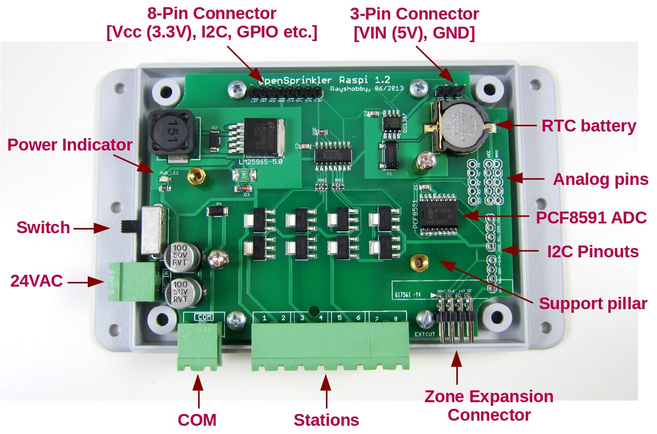
The OSPi package includes the following items:
- One assembled and tested OSPi board.
- Screw terminals.
- one 8-pin cable and one 3-pin cable.
- Enclosure and screws.
The following items are not included and should be purchased separately:
- Raspberry Pi (any version).
- Sprinkler transformer (22∼28V AC).
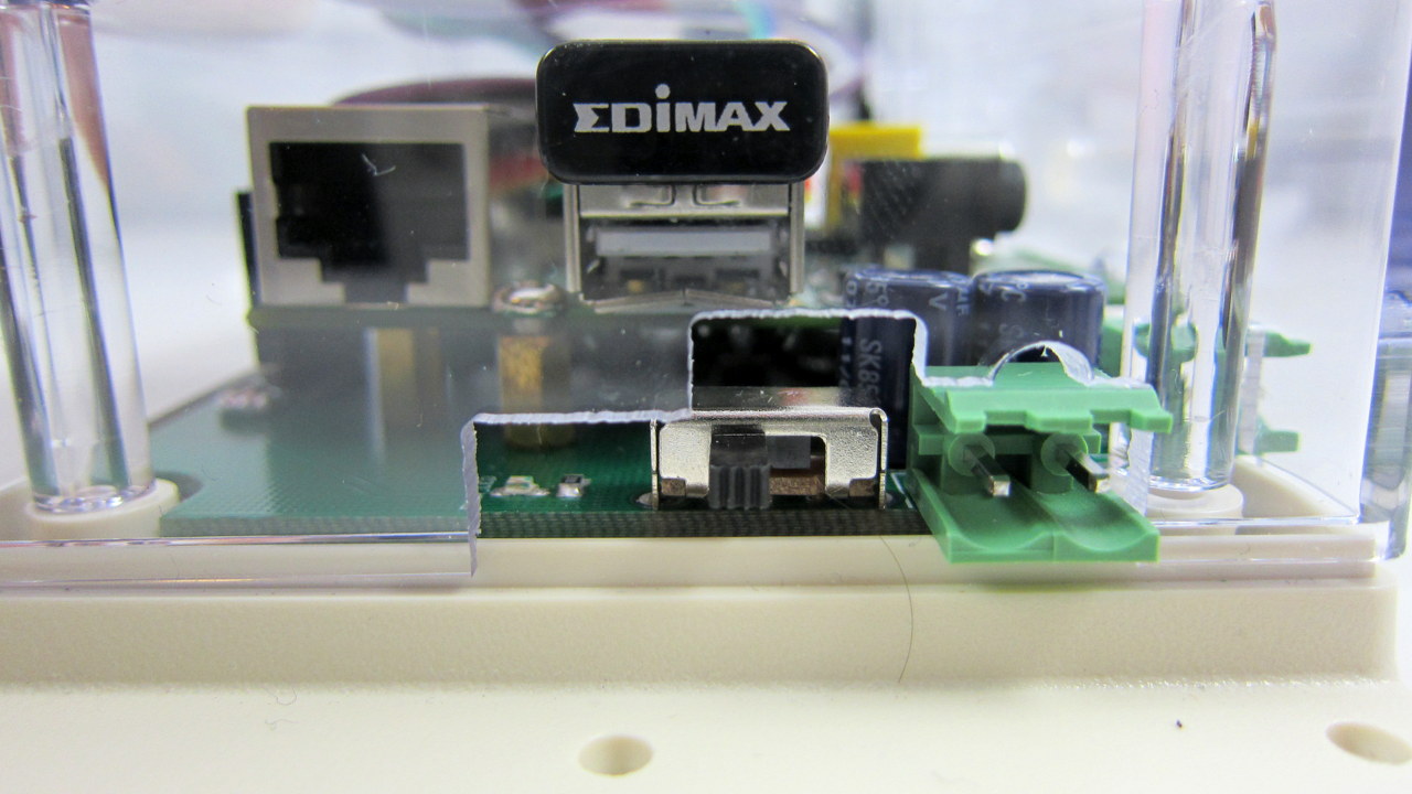
- (Optional) nano-size USB WiFi dongle, such as this Edimax WiFi Adapter.
Power Supply. OSPi uses a standard 22∼28V AC sprinkler transformer. The current rating should be at least 500mA (12VA). Sprinkler transformers can be purchased online (search for sprinkler transformer or 24V AC transformer), or at local home improvement stores. You can also buy a cheap off-the-shelf sprinkler timer which usually comes with a transformer.
OSPi can supply 5V 700mA power to RPi, so you don’t need to use a separate USB power adapter. However, if you would rather prefer a separate power supply, you can simply un-plug the 3-pin cable as shown below.
Important: DO NOT plug 24VAC into the COM port! Doing so may damage your transformer. We recommend using a permanent marker to mark the screw terminal pieces to help you easily identify the two. Also, to reduce the chance of damage due to power surge, please use a surge protector.
Step 1: Test Power Supply
(Note: if you plan to power RPi using a USB cable, you can skip this step).
The first step is to test the OSPi power supply and ensure it outputs acceptable level of voltage. To do so, connect your 24VAC transformer to a 2-pin screw terminal, and plug it into the `24VAC’ terminal port on the left side of the PCB. Then slide down the power switch to turn it on. The green LED on the board should light up.
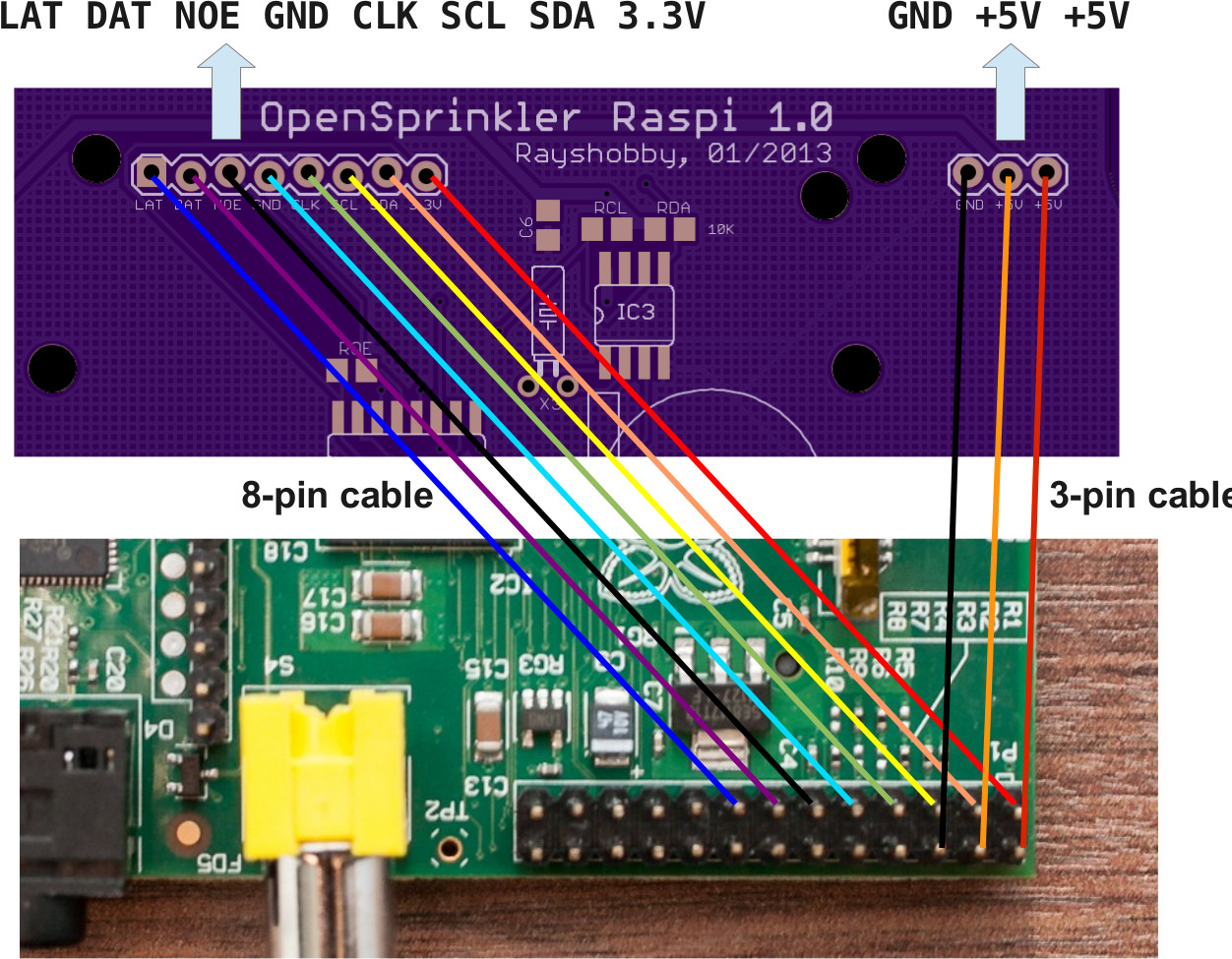
Step 2: Connect RPi to OSPi
Now turn off the power, and connect RPi to OSPi using the 8-pin and 3-pin cables. The 3-pin cable provides +5V power to RPi, and the 8-pin cable connects GPIO pins, I2C pins, and also 3.3V power from RPi to OSPi. Follow the connection diagram and the example photo below.
Important: MAKE SURE both cables are plugged in correctly. Otherwise you may risk damaging your RPi.
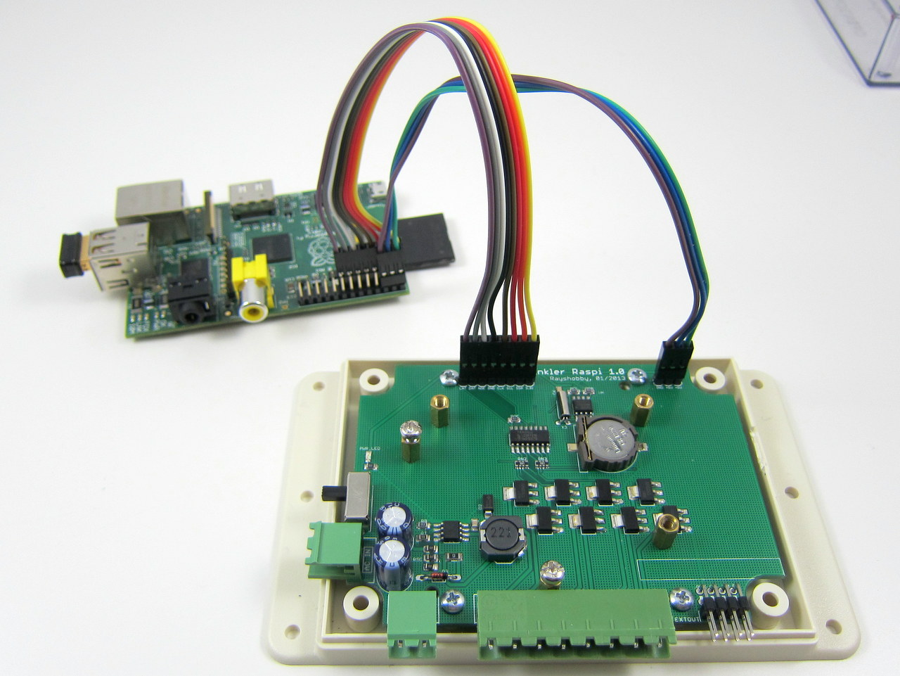
Step 3: Secure RPi to OSPi
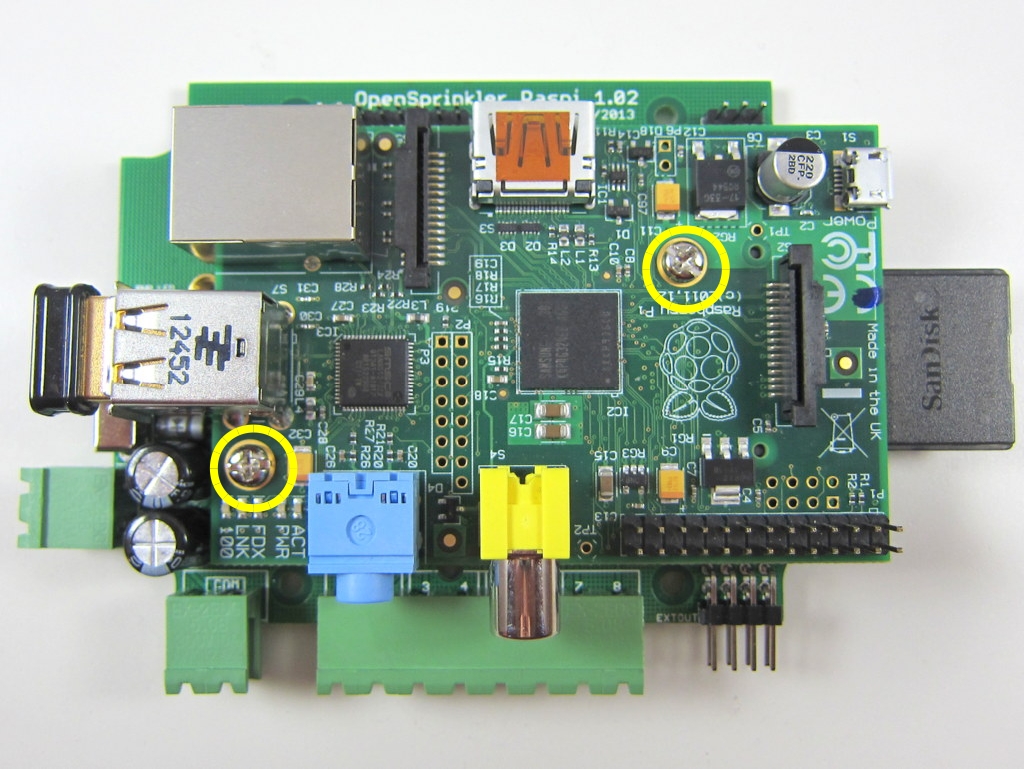
Now carefully place your RPi on top of the OSPi. There are copper separation pillars on OSPi to provide support to the RPi. The locations of these pillars are slightly different depending on the version of your OSPi.
OSPi v1.02 / 1.1 / 1.2 and above
From OSPi v1.02 and above, there are four separation pillars. They can be arranged in two ways. The first way is shown below:
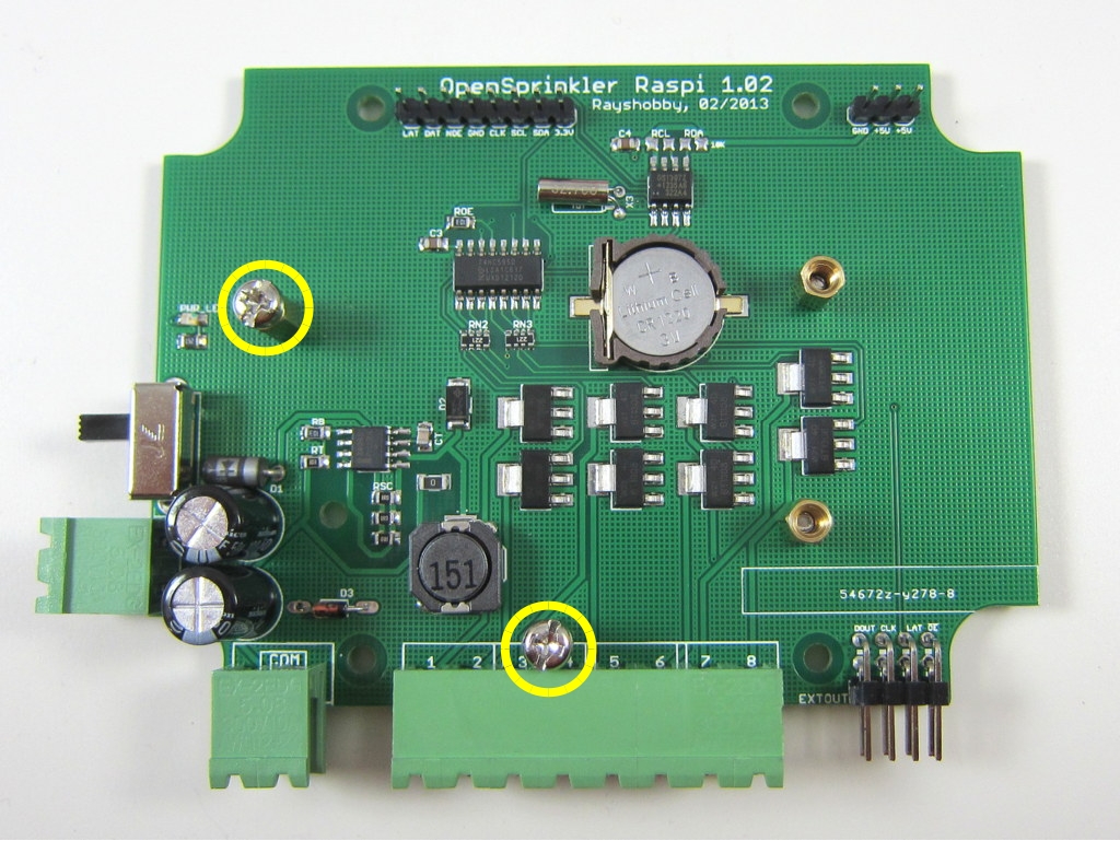
You can use the two screws marked by yellow circles to secure the RPi to OSPi at the edge of the RPi’s PCB. This approach works for both RPi rev. 1 and rev. 2. More details can be found in the OSPi v1.0 instructions below.
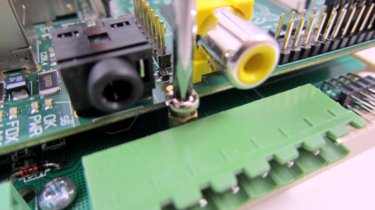
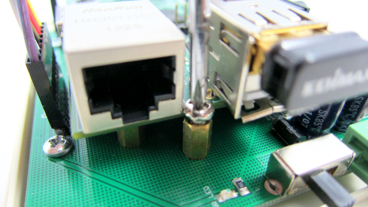
If you own RPi rev. 2, there is actually a better way. RPi rev. 2 has two on-board screw holes, which you can make use of by moving one of the separation pillars following the picture on the left below. Once this is done, you can secure the RPi rev. 2 to OSPi via the two screw holes, as shown in the picture on the right below.
Warning: You should only use this arrangement with RPi rev. 2. For rev. 1, the lower-left pillar in the picture below will get in touch with some of the components on the rev. 1 board. You should NEVER let that happen.

OSPi v1.0 (discontinued)
On OSPi v1.0, there are five separation pillars. In particular, two of them (one on the bottom and one on the left) have screws, which you can use to secure RPi at the edge of the PCB. See the two pictures below:
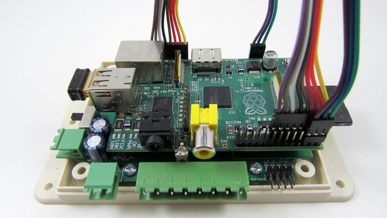
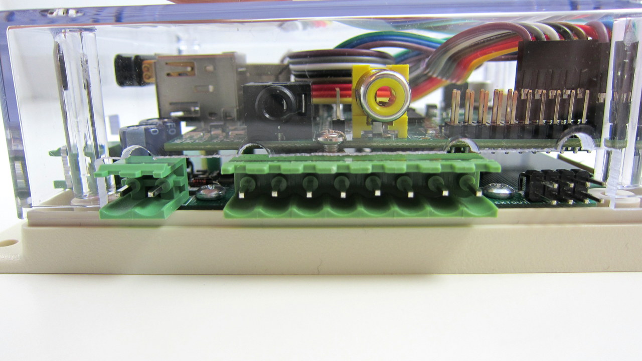
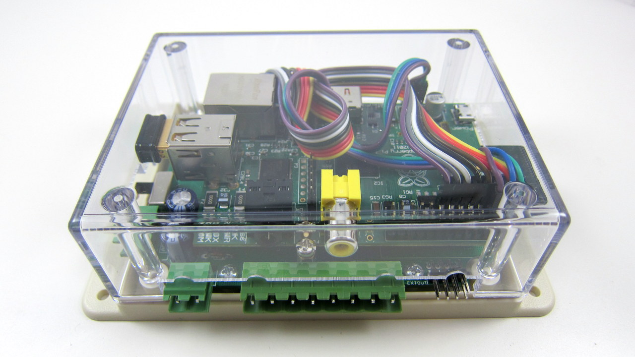
Step 4: Install Enclosure Cover
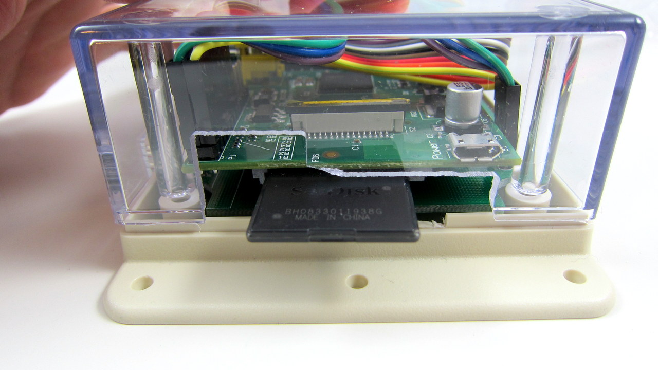
Now install the enclosure cover. There are cutouts on the sides of the cover to allow the SD card and connectors to pass through. Since there is not much room, you need to wrap up the 8-pin and 3-pin cables, and bend the wires as much as you can at the housing of the connectors. It will be tight, but is possible by applying some force carefully.
Step 5: Wire Sprinkler Valve
Finally, you can connect sprinkler valves to OSPi via the COM (common) terminal, and the individual station terminal (1-8). Specifically, a sprinkler valve has two wires. Connect one wire to the COM (Common) terminal (either one of the two ports), and the other wire to an individual station terminal (S1-S8). For multiple valves: one wire from each valve is combined together and that goes to the COM terminal, and the other wire of each valve goes to its corresponding station terminal.
Zone Expansion
Similar to the OpenSprinkler, a single OSPi controls 8 stations, but there is a built-in shift register connector which allows it to be linked to zone expansion boards to enable more stations. OSPi does not limit the number of stations — you can go up to a potentially unlimited number of stations, thanks to the use of RPi.
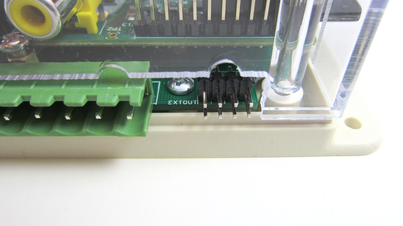
To make the connection, use a 2×4 extension cable to link the EXTOUT port of OSPi to the IN port on the expansion board. If you have received Zone Expansion Board v1.1, it comes with polarized cable connectors: each connector has a ‘bump’ on it, and there is only one way to plug them in (i.e. with the bump facing up). If the bump faces down, you won’t be able to insert the connector all the way in, so this prevents incorrect connections.
Note: if you have OSPi v1.3, you need to remove half of the bump (using scissors or a diagonal cutter). Otherwise you won’t be able to insert the connector, due to the low clearance of the circuit board.
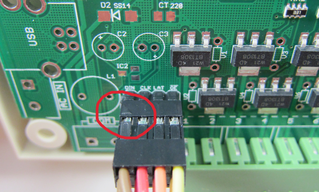
If you have received the original version of the Zone Expansion Board, that does not come with polarized connectors. Here is a simple tip to keep in mind: the connector has one corner marked by an arrow. Make sure on one end of the cable, the arrow is pointing to DOUT, and on the other end, the arrow is pointed to DIN. See the two pictures below for example.
When in doubt, you can always read the PCB silkscreen. The cable should make the following pin-to-pin connections:
DOUT (a.k.a QH*)–>DIN, CLK–>CLK, LAT–>LAT, NOE–>NOE, VCC–>VCC, GND–>GND

If you have multipled expansion boards, you can cascade them by following the OUT -> IN links.
Last bit to keep in mind: you should always use the cable that comes with your expansion board: DO NOT apply the version 1.1 cable (i.e. polarized connectors) to the original version of expansion board, because these cables are wired differently. In any case, if you are not sure, you can always follow the pin-to-pin connections above to check and verify.
Software Setup
One of the biggest benefits of using embedded Linux like RPi is that writing software is much more convenient, and it’s possible to introduce more advanced features like weather-based and learning-based control. You have the choice of your favorite programming language, and virtually unlimited program and data storage size.
Note: OSPi v1.4 is released. Instructions and webpages will be updated in the next few days. For now please check the PDF-version of OSPi v1.4 User Manual.
OSPi Software Details
There are currently three demo programs and two full-featured programs for OSPi. The demo programs can be found in the Rayshobby Github repository; the full-featured programs can be found in the links below:
- ospi_selftest (written in C) turns on each station for 10 seconds in turn. It is useful for quickly testing solenoid connections.
- manual_button (written in Python) runs a simple HTTP server and allows manual control of each station through HTML buttons.
- gcalendar (written in Python) makes use of the Google calendar to schedule water programs. The program periodically polls a public Google calendar to check which stations are scheduled to be on at the current time. Each program is a calendar event and the title indicates the station name(s). Google calendar makes it easy to schedule complex recurring events, and it’s accessible on most devices.
- The full-featured sprinkler_pi program, written by Rich Zimmerman, provides an integrated mobile web page and built-in weather control feature. In addition, its source code can be cross-compiled with AVR/Arduino platform.
- The full-featured OpenSprinkler interval_program (which runs on microcontroller-based OpenSprinklers) has now been ported to OSPi, thanks to the generous contributions by Dan Kimberling. On the pre-configured SD card, this is the default program set to run on start-up. The user instructions are the same with the OpenSprinkler 1.8.3 Firmware User Manual.
Before running each demo, please read the instructions attached in the README.txt under each specific program folder. For the Python-based programs, you need to modify a pin number based on whether you have RPi rev. 1 or rev. 2. For the Google calendar demo, you need to provide a public Google Calendar ID, and install additional library. Also keep in mind that since the programs requires direct access of GPIOs, you will need to run them either as root or use sudo.
(New in OSPi v1.2): OSPi v1.2 has added an on-board PCF8591T A/D D/A converter. Please check this blog post about how to program RPi to interface with the converter.
If you are looking to write your own firmware, you can use the three demo programs as a starting point, which provide important functions such as shiftOut for interfacing with sprinkler valves.
Please feel free to make comments / suggestions on the Rayshobby forum. I also encourage you to take advantage of the Rayshobby User Wiki for adding user-contributed content. Thanks!
