Feed on
Posts
Comments


Content

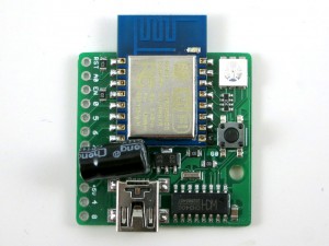
ESP8266 — a very low-cost and flexible Serial-to-WiFi module that has gained a lot of popularity recently. It allows any microcontroller to have WiFi capability by simply using serial communication. In a previous blog post, I demonstrated how to use ESP8266 combined with an Arduino to set up a very simple web server. This time I built a standalone gadget for prototyping called the ESP8266 Toy (or ESPToy for short). There is also a more serious web server demo in the end that shows how to serve HTML files from a SD card, and using JSON and AJAX to implement prettier web design.

You should also know that there has been a lot of on-going development for this module. For example, there is a Lua-based firmware for ESP8266, which is quite amazing. Also check out the community forum here.

As usual, a video demo first:

New ESPToy 1.2:

Original ESPToy 1.0/1.1: Youtube Video Link


ESP8266 module and ESP8266 Toy are available for purchase at Rayshobby Store.


Features

New ESPToy 1.2:

  • ESP-12 SMD WiFi module, pre-flashed with Lua firmware and a startup demo script.
  • 3.3V 250mA linear regulator.
  • Programming using the on-board mini-USB port.
  • One color (RGB) LED, one pushbutton (used as a general-purpose pushbutton as well as for re-flashing firmware)
  • Additional pin headers for connecting external components and/or breadboard experiments.

IMG_0716server_example


Original ESPToy v1.0/1.1 (retired)

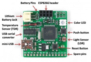
  • ATmega644 @ 3.3V, 16MHz, with CH340G USB-serial converter and Arduino bootloader.
  • 3.3V 500mA linear regulator.
  • Programming in Arduino using the on-board mini-USB port.
  • One color (RGB) LED, one pushbutton, one reset button. (New on version 1.1: one additional button on ESP8266’s GPIO0 pin, useful for firmware upgrade)
  • One light sensor (LDR), one temperature sensor (TDR).
  • One 2×4 pin header to fit ESP8266.
  • Additional pin headers for connecting external components and/or breadboard experiments.

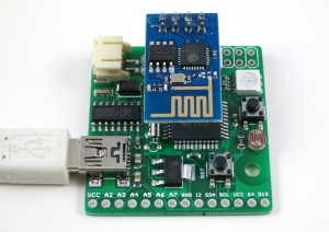
In essence, the ESPToy 1.0/1.1 is a 16MHz Arduino with some handy built-in components for easy prototyping with the ESP8266 WiFi module. Once programmed, the whole assembly can run on battery. There is also a power MOSFET on board to programmably control the power supplied to ESP. This allows you to cut off power to save battery life.

The reason I picked ATmega644 (instead of ATmega328) is that 644 has two hardware Serial interfaces. I am using one for the bootloader and USB communication, the other dedicated for WiFi. This is quite handy and allows you to use the fast baud rates. Also, 644 has twice as much memory as 328, so it’s suitable for building more complex projects.

esptoy_annotatedesptoy_2


Demos

As shown in the video above, I’ve written a few examples to demonstrate the basic features of the ESPToy:

New ESPToy 1.2:

To upload the demo Lua scripts to ESPToy 1.2, download and run the ESPlorer software. The Serial port baud rate is 9600 (default). You can open a demo script, click on ‘Save to ESP’ to save the script as a file to ESP’s internal flash memory space. The script will run right away after uploading. You can also click on ‘doFile’ to re-run the script.

  • Start-up Demo: every ESPToy 1.2 is pre-flashed with a start-up demo. Plug in a mini-USB cable, the blue LED will blink and the WiFi module will start in access point mode, creating a WiFi network with SSID ESPToy-xx. The password is opendoor. Connect to this WiFi network, open a browser, and type in http://192.168.4.1. Use the sliders to change the LED color, and click on ‘Refresh Value’ to read button status and analog pin value.
  • Hello ESPToy!: shows the Serial print function.
  • Blink LED: shows digital pin write, and delay functions.
  • Button Interrupt: shows how to set up interrupt on a digital pin.
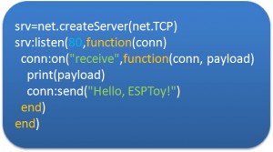
  • Hello ESPToy Server: shows a simple HTTP web server.

Original ESPToy v1.0/1.1 (retired)

  • SearchBaud: this comes handy if you forgot the correct baud rate of your ESP8266. It loops through the common baud rates, sends an empty AT command, the detects the correct baud rate by checking the result.
  • SerialCommand: this demo allows you to send AT commands to ESP8266 through a Serial monitor. Use this demo to experiment with all the AT commands available for ESP8266.
  • ScanNetwork: this demo starts the ESP8266 in AP mode, which creates a local WiFi network (the name is ESPxxxx). Use a smart phone or laptop to log onto this network, then open a browser and type in IP adddress 192.168.4.1. You will see a webpage with a list of detected WiFi networks. Type in the ssid and password of the target network, then click on Connect. The page will redirect in about 10 seconds to show the client IP address of the module on the target network. This is pretty standard approach to get your WiFi-enabled gadget to log on to your target network.
  • WebServer: this is a simple web server demo. It serves a html webpage and uses JSON and AJAX to periodically display the analog pin values. The first two analog pins correspond to the light and temperature sensors respectively, so these two values will respond to light and temperature changes. There are also three sliders to set the color of the on-board LED. As I said before, the demo can run on battery, so this can be used as a WiFi-enabled color LED light. Thinking about a simplified version of the Philips Hue? Yup, this is a poor man’s version of that 🙂
  • WebServer_SD: same as above, except this requires an external SD card slot, so that it can serve bigger and multiple html pages from files stored on the SD card.

Preparation

The ESPToy’s source code is available on Github. Check the README file therein to get started.

Serial Port and Driver:
ESPToy uses a CH340G USB-to-Serial converter. For:

On Windows, the Serial Port name is COM? where ? is a number assigned to the USB-serial chip. On Linux, the Serial Port name is /dev/ttyUSB? where ? is a number. On Mac, the Serial Port name is tty.wchxxx.

Programming ESPToy 1.2

Instructions in this section are being re-organized. For now please refer to the ESPToy 1.2 instructions in this blog post.


Programming ESPToy 1.0/1.1 (retired)
Programming the ESPToy can be done through the Arduino IDE (tested with Arduino version 1.0.6). Because ATmega644 is not a board that appears in the stock Arduino, you will need to copy the atmega644 subfolder (from the hardware folder) to the corresponding hardware folder in your Arduino’s installation directory; same with the ESPToy subfolder (from the libraries folder).

Next, launch the Arduino IDE, select Tools->Board->ESPToy, and the correct Serial port from Tools->Serial Port (see below), then select a program from File->Examples->ESPToy, and finally click on Upload

ESPToy Arduino Library:
The RFToy Arduino library can be downloaded from: http://github.com/rayshobby/esptoy. You can either clone this Github repository, or download it as a zip: https://github.com/rayshobby/ESPToy/archive/master.zip

Pin Assignments:

  • D0: ESP power (active LOW, pulled down by default)
  • D3: push-button
  • D12: red LED (pwm)
  • D13: green LED (pwm)
  • D14: blue LED (pwm)
  • A0: light sensor (LDR)
  • A1: temperature sensor (TDR)
  • Serial: USB serial TX/RX
  • Serial1: ESP8266 TX/RX

Spare Pins: D2 (INT2), D4, D15, A2, A3, A4, A5, A6, A7

Power Options:
ESPToy can be powered by USB or an external battery. There is a battery jack that fits a standard 3.7V lithium battery. In addition, there are two battery pins (next to the battery jack) — you can solder wires to connect a 3V AA/AAA battery pack. Note that the external AA/AAA battery should not exceed 3.6V (because it’s not regulated).


Flashing a New Firmware to ESP8266

Programming ESPtoy with Arduino: I strongly recommend you to learn to use Arduino to program ESPtoy, due to its flexibility and memory efficiency. While Lua firmware is easy for beginners, to write advanced programs, it’s much easier to use Arduino. Follow these steps:

  • Install the ESP8266 core for Arduino
  • Once the ESP8266 core is installed, you can select Generic ESP8266 Board, upload speed 230400, flash mode dio.
  • Before plugging in USB cable, press and hold the on-board button (on ESPtoy), then plug in the cable, and release the button. This way, the board enters programming mode.
  • Select the correct serial port (on Windows, it shows up as COMxx; on Mac, it’s generally named /dev/tty.wch…; on Linux, it’s typically /dev/ttyUSB0). Then upload.

On ESPToy 1.2 and 1.1: there is a pushbutton button (on version 1.1 it’s at the upper-left corner) — it’s connected to ESP8266’s hardware GPIO0 pin. If this button is pressed when powering up ESPToy, the ESP8266 will enter bootloading mode waiting for a new firmware. I recommend using the esptool python program to upload firmware, which is very easy to use. Specifically, in command line, run
./esptool.py write_flash 0x00000 xxxx.bin
where xxxx.bin is the firmware name.

On ESPToy 1.1, use the SerialCommand sketch to prepare ESPToy as a serial relay.


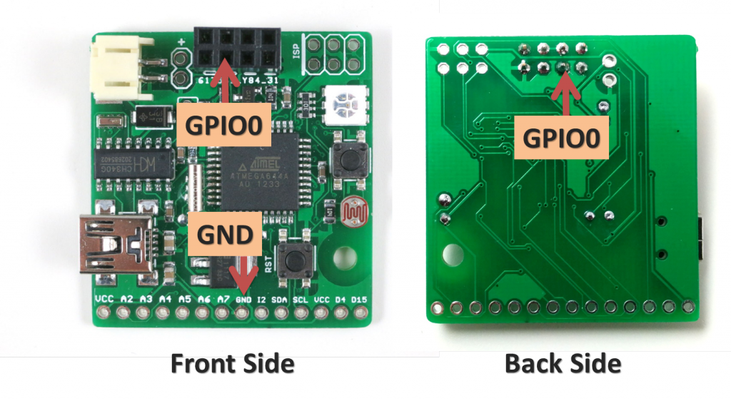
For ESPToy 1.0 (retired): to let ESP8266 enter bootloader, you need to solder a wire from ESP8266’s GPIO0 pin to ground. Specifically, if GPIO0 is pulled to ground, upon power-up ESP8266 will enter bootloader mode waiting for a new firmware from the Serial interface. In contrast, if GPIO0 is pulled up (to VCC), ESP8266 will boot into normal operation mode.

The picture below shows where the GPIO0 pin and a ground pin (any ground pin on the board should work). The wire should be soldered at the back of the circuit board. You can also connect a switch in series on the wire to easily switch between bootloader mode and normal mode.

esp_gpio0

Once this is done, you can flash the SerialCommand sketch to ESPToy, which will make it serve as a Serial relay. I recommend using the esptool python program to upload firmware, which is very easy to use. Specifically, in command line, run
./esptool.py write_flash 0x00000 xxxx.bin
where xxxx.bin is the firmware name.


Purchase Link

58 Responses to “Introducing the ESP8266 WiFi Toy (ESPToy)”

  1. Ramon says:

    Hi!

    Great work, I want one 🙂 is there a possabillity that you could create a version for the ESP8266 ESP-07, or ESP-12 version it has more GPIO’s available and could make the board nice and clean looking!

    Thanks,

    Ramon

    • ray says:

      For the ESP-12 version, I just noticed (after I posted ESP8266) that a new development board called nodemcu is now available. It uses the Lua firmware, which allows you to run programs on the ESP-12 chip itself. It’s quite amazing, you should definitely check it out. I am not familiar with Lua so I can’t comment on the pros and cons, but it does look quite powerful and flexible.

      • Ramon says:

        Yes I’ve seen it to it looks great, but as I’m used to the whole arduino environment it would be perfect to add the ESP-03, 07 or 12 version to your board it has far more GPIO’s available! But I really love your board with the sensors, rgb.. I have tried to combine the schematic of the NodeMCU board and yours, but my lack of Eagle skills make that impossible 🙁 I really hope you can add a board which has place for an ESP-03, 07 or 12 I would definitely buy one or more!!

      • ray says:

        I am waiting for my first nodeMCU to come, and then I will see if it makes sense to design one around the ESP-12 chip. Anyways, thanks for your suggestion.

  2. zmemw16 says:

    does the second crystal on the 644 provide overtones? 🙂

    • ray says:

      There is one crystal (12MHz) for the CH340G USB-serial chip, and one crystal (16MHz) for the 644 microcontroller.

      • zmemw16 says:

        from zip file, esptoy_v1.png: please review pins 7 & 8 of atmega644.

      • ray says:

        OK, I see. The two crystals are the same — it’s just that one is SMT and the other is through-hole. I often do this to give me flexibility in choosing which type of crystal to use.

  3. zmemw16 says:

    not actually something i’d seen before so it didn’t occur to me.
    as i’m homebrew pcb’s it tends to be all smd or all pth, but i also
    dislike drilling holes as they’re never all in line:-)
    .
    stephen

  4. Rando says:

    Is there a BOM listing for this board? I just ordered one to test with, and would like to make this my first attempt at SMD soldering.

    I’m having trouble finding a source for the CH340G, do you have a recommendation? (Seems to work great on Windows 8.1).

    Thanks, as always, for sharing your outstanding work.

  5. Ahmed says:

    Great work, is it possible to port the Arduinolifx bulb on: https://github.com/kayno/arduinolifx to the ESPToy?
    If yes then please help me to do so.

  6. TALIAN says:

    in your example “server” has made a mistake
    1 in the AT + CWMODE = 1, “esp” will not operate as a transmitter and will not be visible in the network, mode needs 2 or3
    2 need to reset the AT + CIPMODE = 0 – otherwise there is no transmission and reception
    3 I am not a programmer C ++ but apparently there is more erroneous actions – because after the page is loaded on the smartphone (18-25 seconds), and attempts to adjust the brightness of the LED is issued request to the server and from a completely freezes
    I use ATMEGA2560 (code adaptiroval- including selection ESP)
    I would like to understand how to use ESP – Enter numbers with smartphone Arduino through a web server
    show worker (right) of the Code that you have on video (last part)

    Sorry for my english, I’m from Ukraine

  7. GML says:

    Ray,
    Love your products! I wanted to use the ESPToy as part of a RV project and would like to convert the temperature reading to C or F. Can you tell me what temperature sensor is used? (I looked at the documentation for the SquareWear2 in case it was the same sensor but the formula doesn’t yield a reasonable result.)
    Thanks.
    Grant

  8. Dave says:

    Hi Ray,

    I just received my ESPToy and it looks like a newer version (v1.1) than what’s shown on your site. I noticed that there’s a 3rd push button switch next to the lithium battery jack. What is that new switch for?

    Also, I’m having intermittent results trying to connect to the 192.168.4.1 web site. The ESP8266 is providing a good WiFi signal and I’m able to connect to the ESP_xxxxx SSID. But I’m not always able to access the web page. Any advice or tips? Thank you.

    Dave

    • Dave says:

      OK, I believe I figured out what the additional push button is for. There are a couple of labels next to the switch, “GP0” and “GND”. Correct me if I’m wrong but it looks like this new push button will pull GPIO pin 0 to ground to enter the ESP8266 in to bootloader mode upon power up.

      I’m also having better results connecting to the ESPToy’s web site. Great product!

      Dave

      • ray says:

        You are correct: the additional button on the new version is connected to GPIO0. If this button is pressed when ESP8266 is turned on, it will enter bootloading mode and wait for a new firmware. Thanks for figuring this out yourself, I will add the description to the website soon.

  9. Keeron says:

    Having some trouble with the new ESPToy that I got in the mail. I tired playing with the example sketches and had success early on with the demo sketch, but thereafter no luck with others. I am now trying to flash the latest firmware as per the steps on this blog but that’s also not going anywhere. If I press and hold the button, while plugging in the USB – do I need to keep the button pressed until the firmware is uploaded, or release it after some lights go on?

    Also, what method are most folks using here to upload the new firmware? I tried couple of tools mentioned in the ESP wiki.

  10. Keeron says:

    So after about 3-5 mins of wait (after uploading the demo sketch), I finally got the page again at the said IP address. Not sure why this is taking so long though. I’ll try other sketches now

  11. Carl says:

    ESPToy – Arduino Problems:

    I can’t get my Arduino to recognize the ESPToy (ATmega644) as a board.

    The instructions are a little vague as to where to put the folders, so maybe that’s a problem.
    Also, I’m using V 1.6.0 of the Arduino IDE, but the instructions say it was tested with V 1.0.6. Maybe that’s a typo?

    If anybody has advice about this, I would appreciate it. For example, exactly where do I put the atmega644 folder and the ESPToy folder?

    -Carl

    • ray says:

      It’s 1.0.6, an old version. 1.6.0 is the new version that just came out a couple weeks ago. Because 1.6.0 has changed the way boards are defined, it requires some changes to boards.txt. Also, 1.6.0 adopted a new version of avr-gcc so there may be compilation errors too. For now, unless if you have a strong reason to go with 1.6.0, I would suggest staying with 1.0.6.

      • Carl says:

        Ray:

        I backed down to V 1.0.6 of the Arduino IDE, and it’s working now.

        I only ran with it briefly, but it seems a little cranky about starting up reliably. I had to reset the board a couple times, because it would lock up or the WiFi connection would disappear. I’m going to keep playing with it and see what happens.

        Thanks for the help.

        -Carl

      • ray says:

        You may want to upgrade ESP8266 to the latest firmware (0.9.5) and see if it makes the module more reliable. The firmware on ESP8266 that comes with the ESPToy is using a fairly old firmware (0.9.2?), and I know it has issues where if too many AT commands are received it tends to restart itself.

  12. Ishben says:

    Hi there guys,
    i just got mine in the mail today and i have follow all the steps as on the video above and it seems to be working just fine until i even get an IP address but when i get to the sketch “WebServer” i load the sketch to my ESPtoy and then i go to the IP address it gave me ,the webpage Never loads up i have tried,Safari,Internet explorer,Mozilla,Chrome and it never loads,this is what the serial monitor on the arduino IDE says :

    AT
    AT+CWMODE=1
    AT+RST
    AT+CWJAP=”****** ***”,”********” <-Here it's where my SSID and PASS show
    AT+CIPMUX=1
    AT+CIPSERVER=1,80
    ip addr:AT+CIFSR
    AT+CIFSR
    192.168.1.116
    OK

    I have put my SSID and PASSWORD in the sketch but i don't get it to work is there something i might be doing bad or it is just my luck and i hit the lucky one.
    well guys thank you and i appreciate your help

    • ray says:

      The last line of output:
      AT+CIFSR
      192.168.1.116
      Suggests that it has connected to your network, and obtained a valid IP. When you say not working, what specifically do you mean? Did you type in the IP address 192.168.1.116 in a browser and not getting any response?

      • Anonymous says:

        Hey there my bad I didn’t say what is not working, ok after it gives me an ip Address I go to my web browser and I type in the module’s IP I hit enter and the webpage with the example (like the one in your video) never loads, I don’t get any response it just says “cannot load the webpage you are requesting” (Safari,google chrome,mozilla,Internet explorer on any web browser) That is the issue I’m having
        Thank you !

      • ray says:

        Due to browser’s caching, sometimes it doesn’t work as expected. Here is my suggestion: power off ESPToy and power it back on, after it’s done initializing, open a browser and type in 192.168.1.116/ja (assuming 192.168.1.116 is the IP address). See if it responds with the JSON data. If this is successful, you can then do 192.168.1.116/cc?r=128 to see if it responds to LED color change. If both are successful, the problem seems to be that the browser can’t load the HTML data output by ESPToy, and we can diagnose further there.

  13. Andrew Moizer says:

    Just stumbled on this board. Looks like a neat solution.

    I just like to check that all there is for “voltage regulation” for the single cell lithium battery input is the dropping diode?

    thanks,
    Andrew

    • ray says:

      That’s right – because a Lithium battery has maximum voltage of 4.2V, and the diode drops about 0.7V, that sets the voltage to a maximum of 3.5V, which is within the acceptable range of ESP8266.

  14. A.Bottle says:

    Hi, I am installing ESPToy support for new Adruino IDE 1.6.2 with following result.
    Are you planning some compatibility upgrade, please?

    C:\Program Files (x86)\Arduino\hardware\atmega644
    contains BOARDS.TXT extracted from ZIP

    ERRORS:
    Could not find boards.txt in C:\Program Files (x86)\Arduino\hardware\atmega644\cores. Is it pre-1.5?
    Could not find boards.txt in C:\Program Files (x86)\Arduino\hardware\atmega644\variants. Is it pre-1.5?
    WARNING: Error loading hardware folder atmega644
    No valid hardware definitions found in folder atmega644.

    • ray says:

      The boards.txt only works in Arduino 1.0.x. The new Arduino 1.5.x and 1.6.x have changed how the boards are defined. It’s not hard to modify boards.txt to make it compatible with 1.5.x and 1.6.x, I just haven’t got time to do so. So for now please use Arduino 1.0.6. You can have multiple Arduino software co-exist.

  15. Karl Laun says:

    I received my ESPToy v1.2 today and was trying out the installed sample sketch. I can successfully connect to the EXPToy-xx WiFi network using the provided password. However, when I try to access the device’s web page via an iOS device, the small, blue LED flashes briefly and I get a message something to the effect of “Safari cannot open the page because the network connection was lost”. To further investigate, I tried a couple other iOS browsers on both an iPhone and iPad with similar results. However, I CAN log in with a Win7 laptop and control the LED via the broadcast web page. I ran into a similar issue with a stand-alone ESP8266/LUA module on another project where I could only access the ESP web server with on Apple devices. It appears to be an iOS-specific display issue. Ideas??

    • ray says:

      After seeing your comment, I did some extensive test. I can verify the problem — on my Windows computer it’s giving me the same issue (i.e. module resetting after I connected the computer to ESPtoy WiFi). I did a bunch of test and it turns out the issue is due to the linear regulator. On this particular batch, the 3.3V linear regulator uses MCP1700-33, which seems to be not so powerful as the LC7333A used in the previous batch. As a result, when ESP8266 draw more current the voltage drops, triggering a reset. This problem wasn’t discovered during testing because we were using a mini-USB cable connected to an unpowered USB hub. The effect of going through unpowered hub is that the USB voltage (which is normally 5V) is about 4.5 to 4.8V. This helps reduce the issue with the linear regulator, because the lower the input voltage, the more current it can supply (the maximum current is the maximum power dissipation divided by the difference between VIN and VCC. So the lower the VIN, the lower the difference between VIN and VCC, hence more current supply).

      If you shoot an email to [email protected] we will arrange to send you a new ESPtoy free of charge. In the meantime, you can use an unpowered USB hub like described above. Alternatively you can directly either connect 4.5V (3x AA/AAA) to VIN-GND, or, connect 3V voltage (such as 2x AA) to VCC-GND to power the board. These should solve the power issue.

  16. Karl Laun says:

    Hi Ray,
    Thanks for the replacement offer, but since I could get the module to work with other browsers, I didn’t think that power was really the issue. I put the ESPToy away for a while, and found recently that the new code that you posted on Github solved the problem I was having. Works fine with my iOS devices now. Thanks for providing the update!

    Karl

  17. Lynn N says:

    Hi,

    Please tell me how to connect arduino to Dropbox or Google drive.

    Thanks.

  18. Rando says:

    R.,

    I have an ESP, wondering how this would work as replacement for LUA?
    Arduino-compatible IDE with ESP8266 support, https://github.com/esp8266/Arduino
    Do you think it is a good idea?
    Best,
    Randy

  19. Siddhesh bobhate says:

    can use ESP8266 with cc3200 launched if yes then please give me the idea.

  20. kevin says:

    Does ESPToy charge the lipo battery by any chance (if connected via usb)?

  21. JohnSL says:

    I’ve been looking at your LiPo circuit and have some questions. The schematic says the three diodes in the 1.2 version, with D1 and D2 marked as LLN4148, while there is no label for D3 (but it’s marked 1N4148, as are the other two diodes, in version 1.3). Looking at the 1.2 board that I have, D3 is rectangular and the other two diodes are cylindrical, so they’re obvious two different types of diodes. Additionally, I measure about a 0.7 drop across D3, but only 0.5V across D1 (or D2). Can you provide more information about the model numbers for these diodes?

    • ray says:

      It doesn’t really matter. They can any generic diodes which can drop 0.6 to 0.7V. The specific ones on the board are 3.3V zener diodes for D1 and D2, and S1A for D3. But they can all be the same, and LLN4148 is fine too. The only reason I used S1A for D3 is because I accidentally used a different SMD profile for D3 and S1A would fit well for it. Otherwise I would have used the same for all three.

  22. jeny says:

    Hi,

    Can you redesign ESPToy 1.0/1.1 (retired) for my requirement, on payment basis?

  23. Croc says:

    Hello Ray,

    I had the moment that you change from version 1.1 to version 1.2.

    We arrange that I will take the 1.2 version and it will be the same. I bought the earlier version because I was intrested in the scannetwork first the ap mode and than you can exchange to your own network in the html page. I am waiting for the example for the 1.2 version, but is still not availible. I already send a personal mail without any response.

    Hope to hear soon.

    • ray says:

      Now that you can use the Arduino IDE to directly program ESPtoy (without the Lua firmware), there is no need to use the earlier demos. The Arduino examples include one that scans nearby WiFi networks. Check this website: https://github.com/esp8266/Arduino

      • Croc says:

        Hello Ray,

        Thank you for your response.

        Do you don’t have a lua version of this ? instead arduino?

        Already thanks for your response.

      • ray says:

        I strongly favor using Arduino instead of Lua — the Lua firmware takes a lot of resources (including RAM and flash memory space). There is practically nothing that you can do with Lua but can’t do with Arduino. Plus Arduino is C++/Java style, which is a more familiar language to most people. Lua actually requires some learning curve.

  24. Mike says:

    Can you provide some guidance as to which ESP8266 board type to pick when using the ESP8266 Arduino IDE? Is there a supported board which is close enough? Or could you contribute to updates to the ESP8266 Arduino project to add v1.2 as a supported board type? Looks easy enough to add a new entry to boards.txt and a new variant folder with a correct pins_arduino.h file, if one knows all the details of the v1.2 device, which you would. Thanks!

  25. ElmerD says:

    Hi Ray:

    I just saw your video post and am interested in purchsing the esptoy. I think you have a great product, compact and easy to use with useful features. I am looking to using it as a programming jig for my ESPv12 modules. Is it possible to purchase the ESP toy with the ESP module not soldered in? My intent is I will instead solder in a 2mm pitch header and “pop in” the ESP modules I need to program, proceed with the programming, and then popping the ESP module off for final installation. If this is possible, I am interested in purchasing three ESP toys for testing purposes. Thank you.

    • ray says:

      Thanks for your interest. Unfortunately all the assembled boards come with ESP module. We do sell the ESPtoy bare PCBs, which you may consider for building your jig.

  26. Paul Bellett says:

    Hi Ray,

    I would buy these devices in bulk if there was a way that you did not have to type
    in the darn ip address in the browser to access it. My application is for medical practice waiting rooms for members of the public that use their smart phones that have access to a WIFI network, but the idea is to deliver a warning information webpage about the procedures/protocols of the establishment.

    Best regards

    Paul

    • ray says:

      Are you planning to use ESPToy as a WiFi server or client? As a WiFi server, it probably won’t handle more than a few connections and you’d have much better chance using a Raspberry Pi.

  27. Bob hamilton says:

    Hi Ray,

    I am hoping to connect the moisture sensor you worked with to the internet using an ESPToy 1.22.
    Any chance you or anyone has ported the Arduino sketch you wrote to Lua?

    Thanks in advance,
    Bob

    • ray says:

      Recently I’ve been using Arduino exclusively to program ESPtoy. While Lua is easy to get started, it’s too heavy on using resources (to the point that it’s difficult to allocate any substantial memory on the fly). So I have abandoned Lua in favor of Arduino. Also, using Arduino means you can make use of thousands of Arduino libraries with little to no modifications.

  28. dharmendra says:

    Hi Ray,
    I simply want to serial to wifi to wifi to serial, for wireless data communication in between two esp8266 module, serial-wifi-wifi-serial using esp8266 with Arduino.
    please help me. thanks

Leave a Reply