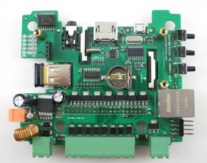
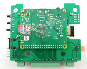
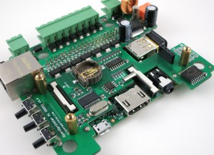
When I first had the idea to design OpenSprinkler Pi (OSPi), a secret motivation was that one day I figured out how to fit Raspberry Pi into the existing OpenSprinkler enclosure. Yes, it sounds silly, and you can laugh at it; but if you understand how much it costs to make an injection molded enclosure, and how difficult it is to predict the market and demand, you will see why I wasn’t quite ready to invest on a whole new enclosure for OSPi.
The experience last year has proven that OSPi is quite popular. I really enjoyed seeing the amount of community development on it, primarily due to the low cost of RPi and the flexibility in programming the RPi. We’ve also seen continued evolution of RPi, from the early A and B models to B+ and more recently A+. On the plus side, it’s exciting to see that RPi continues to become smaller and cheaper. The A+ version is now 25% smaller and you can get one for just $20. On the other hand, I am sure the different versions created some challenges in re-designing products powered by RPi. Because each version has different peripheral elements, size, screw hole locations, it’s quite difficult to design one board that fits all versions.
So in a way, I felt lucky that I wasn’t too hasty to invest on a dedicated enclosure for OSPi, because whatever I would have designed would probably not fit A+ in the end. But the lack of a dedicated enclosure has always been the major confusion about OSPi: from time to time I receive questions about why the cutouts on the enclosure do not match RPi, and then I have to explain. It’s not ideal.
Here comes the good news: with RPi A+, it looks like I may be able to ‘close the gap’ finally — that the injection-molded OpenSprinkler enclosure will finally fit OSPi, without confusing mis-alignment of the cutouts, and with buttons and LCD, just like the microcontroller-based OpenSprinkler!
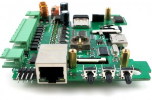
Here are some pictures to show you the proof-of-concept:
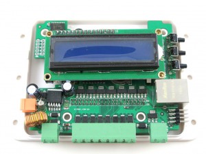
Mounting RPi. The most dramatic change is that RPi A+ will be mounted at the back of the OSPi circuit board. This is necessary to make space for the LCD (explained below). This may look surprising, but because A+ is quite flat, there is sufficient space at the back of OSPI to fit it, except HDMI, USB, and other peripheral connectors, which I’ve made cutouts for.
There is no secret that I’ve always enjoyed solving the ‘how to fit RPi into the OpenSprinkler case’ problem. It’s like a geometry puzzle for me. Often constraints push me to think of new solutions. So bear with the nerdy side of me 🙂
LCD. Next, for the LCD I am using I2C LCD — it’s the standard 1602 LCD with a I2C module at the back. This turns out to be very important, because I2C LCD needs only 4 pins in total (VCC, GND, SDA, SCL), significantly reducing the pin requirement and saving space. You can buy these with pre-soldered I2C modules, at very small added cost.
Buttons. There is also space to fit 3 push-buttons on the right-hand side of the circuit board. The physical buttons can be quite useful for triggering events or performing manual sprinkler control.
Ethernet. Lastly, I don’t want to waste the cutout for Ethernet jack, so I even added a ENC28J60 Ethernet controller. This is a useful add-on for RPi A+, which doesn’t come with an Ethernet jack itself. It took me quite while to figure out how to re-compile the RPi kernel to support this Ethernet controller. Don’t expect it to be very fast, but it comes handy if you really need wired Ethernet connection. Most people will still prefer the WiFi dongle.
One of the biggest drawback of this design is that RPi A+ will now be permanently soldered onto OSPi, because there is simply no space in height to put pin headers. This is not ideal but I can’t think of a better choice. The other potential issue is the heat dissipation of RPi — although there is some space between RPi, OSPi, and the enclosure bottom, it can become an issue during hot summer days. There is some space on the board to make vent holes, so I will see what I can do.
To summarize, this is a proof-of-concept design for OSPi A+ — it will finally make the injection-molded enclosure work perfectly for OSPi. Because this is a very early prototype, don’t expect it to be available anytime soon, although I do hope to make it ready by summer time this year.
Feedback, comments, and suggestions are welcome. Thanks!
Great concepts Ray – I can’t wait to see what we can do with that LCD. I assume you’ve looked at OLEDs and they are just too expensive at that size? I say that because an OLED would be a little sexier and in my opinion OSPI needs a little sex appeal.
I see people creating/kickstarting new sprinkler controllers seemingly every month and I wish they would put that energy into supporting an open project like OSPi. I know it means they wouldn’t be able to attempt to build a business, etc. but the open nature of OSPi is just so compelling to me because we can all share knowledge/expertise/etc.
Having both buttons and a display are a major improvement in usability and increase the visual appeal.
I continue to have a need for a physical Ethernet, so thanks for including it. I kept hearing horror stories about the lack of reliability in the USB WiFi dongle.
About OLED: I’ve used it on the RFToy and I like it a lot. However, the OpenSprinkler enclosure is designed for 1602 LCD so I don’t have any choice — if I use OLED, it will not fit the LCD cutout.
Indeed there are tons of new web-based sprinkler controllers popping up these days. OpenSprinkler will remain an open-source product, so that will always be an unique feature of it.
When you say it is designed for the 1602, you mean you need an 80×36 mm display? I see several 80×36 OLED color character displays out there. Several are designed as drop-in replacements to the 1602.
Graphics would be even cooler but again, I appreciate that the cost (@ $20 unit) might get a little crazy. Just as an example of an 80x36mm unit: http://www.scoperks.com/product/100×16-graphic-oled-blue-characters-on-black-background-80x36x10mm/6411164/
Ah, interesting, I didn’t know there exist 80×36 OLED displays. Thanks for pointing it out, I will definitely look into whether I can source them at better prices.
The prototype looks cool. I’ve been wanting to go with a Pi version but always had display and button envy. I even thought about getting a dedicated cheap android tablet and mounting it in the controller box so that controls and an interface would be readily available.
It’s neat to see things evolve. Keep up the great work.
I am curious, will this new sardine can version support the 433mhz transmitter? I have been lurking for about six months and am having a hard time deciding whether to buy the ATmega or the Pi version. Frankly, I really want the rain sensor and the radio features, but I am pretty impressed with the interface for Google Calendar too. It looks like the Pi version is about to play catch up and offer all of the features of the ATmega. If so, I am getting excited!
Hi Ray,
your note regarding the header spacing requiring soldering reminded me of another A+ hat that got around that by using SMT headers mounted on the top of the PCB but allowing pin entry from beneath. I can’t find that project now but I found that kind of header: http://wppro.com/content/en/products/female-headers/254mm-pitch/product/3492.html
Interesting pointer, thanks. Well, the challenge I am facing is that the RPi A+ has to be mounted from the back of the PCB (because the LCD needs to be mounted from the front). So ideally I would like some sort of female pin headers that face backward (like those backfire LEDs). The goal is such that the A+ can be inserted from the back of the PCB into the pin headers, and so there is no need to solder the pins permanently to the PCB. I don’t think this type of pin headers exist though.
I re-looked at the link, and I think you are right: this is the type of pin header I needed! It allows the male pins to go through it from both sides, so yeah, this is exactly what I needed. Thanks!
I’m curious as to what the progress on this is. I was just about to purchase a OSPi thinking that I would just hack together my own I2C display, but then I stumbled onto this. Now I’d really like to get in on this. When you say that the network connection won’t be very fast, will still handle the stock Open Sprinkler web and mobile interfaces? Is the difference between that and wireless noticeable? Any idea of the cost for this yet?
I haven’t made much progress on this and I don’t think we will have any official version until later this summer. Once ready the plan is to sell this version as a fully assembled OpenSprinkler Pi (with Pi built-in) and the price will be no less than the microcontroller-based OpenSprinkler.
Any chance of purchasing one of these beta boards? I love my OSPi (not sure if I have a v1.3 or v1.4), but in order to gain WAF (Wife Acceptance Factor) points it needs to be controllable from the device itself, which means buttons and a screen.
Thanks in advance.
Sorry the development of the A+ version is temporarily on hold. If you really need buttons and screen, I suggest that you consider the fully assembled OpenSprinkler (i.e. microcontroller-based version).
Just wanted to weigh in and let you know I’d buy this version today if it existed.
Hi Jake, I’ve pretty much abandoned this version because it really only works for OSPi A+ and I am not sure how many users prefer A+. Instead, I’ve found a way to design an acrylic enclosure dedicated for OSPi and hence the next version of OSPi will not be limited by the OpenSprinkler enclosure any more and can have LCD and buttons.