For a while I’ve been looking for a way to switch household power line (110V) devices. One of the simplest options is to use a relay that is connected to the power line. This is easy in concept but quite dangerous to work with. You don’t want to accidentally touch the power line wire and shock yourself. A much better option is to use the powerswitch tail, which insulates the relay and the relevant circuity inside a plastic enclosure, leaving only two MCU pins to interface with. Much safer. But you still have to run wires between your MCU and the power socket. I am more interested in an wireless option.
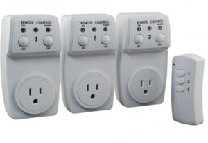
Recently I purchase a set of remote controlled switch sockets from Amazon. It comes with one remote and three sockets, each of which can be individually switched. The whole package is quite cheap. The way this works is that you plug the sockets into the wall, and when you press a button on the remote, the corresponding socket will switch, thus turning on or off the device connected to the socket.
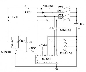
I took apart the remote control and found that the circuit is quite simple. It’s based on an HT2262 remote control encoder and a 434 MHz transmitter circuit. In fact, the schematic of the circuit is well documented in the datasheet of the encoder:
From the schematic, it’s quite clear that when a button is pressed, the input voltage is fed to one of the encoder pins (as well as the VCC pin of the encoder). Then the encoder will send the signal to the RF transmitter circuit. The RF signal will be received at the power socket side and decoded. Very simple. Now, to use my Arduino to interface with this power switch, all I need to do is to simulate a button press by sourcing a positive voltage to wires labeled SW1, SW2, SW3 etc. It turns out that the HT2262 can work with a fairly wide range of voltage: from 4V to 18V. Clearly the 5V output from an Arduino IO pin falls within the acceptable range. So I can simply connect those wires individually with Arduino I/O pins, and write a program that outputs HIGH momentarily when I need to switch a device. The only downside is at 5V the transmitting range is limited. The higher the input voltage, the longer distance it can transmit. So a more flexible design is to have a ‘source’ driver to supply higher than 5V to the encoder.
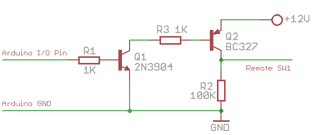
This can be done by using a transistor based high-side switch. Here is a schematic:
Basically, when the IO pin outputs low, transistor Q1 (NPN) turns off, and its collector is in high impedance status. Hence Q2 (PNP) is also off. Now, when the IO pin outputs high, Q1 conducts, driving the gate of Q2 low. Therefore Q2 also conducts, sourcing +12V voltage to the encoder. The reason to use such a high-side driver is to be able to switch a high voltage (>=12V) using a relatively low-voltage (<=5V) control signal from the MCU.
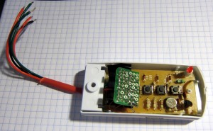
I implemented this method on a small proto-board. Since the remote control has 3 buttons, I made 3 copies of the above high-side driver, and the entire circuit fits nicely inside the remote control cover. I soldered five wires out: +12V, GND, and three control wires. A picture is shown on the left.
With this modification, I can now switch power line devices such as home lights and heaters using a microcontroller. Better, I can connect the remote control with my OpenSprinkler Controller, thus I am able to control power line devices through a web interface. The video below show a demo. Enjoy!
Whats the max Amps they are rated at? I can’t find anything on the load they can take.
(Sorry, my previous comment was not relevant).
I just took a look at the ratings, these sockets are rated at 10A @ 120V.
Today I had a chance to take apart the power socket (the receiver side). I noticed that inside there is a relay rated at 16A @ 250VAC. I assume this means it can handle up to 16A even though the spec says 10A.
Nice write-up. I have a remote-controlled outlet at home and have been wanting to hook an Arduino up to it as well, but I was thinking about using an optocoupler instead of transistors. Do you think that will work or will the optocoupler have too much resistance to complete the circuit?
I think optocouplers would work just fine. The input of the encoder is probably MOSFET based, so it’s activated by voltage instead of current. But I should do a test before I can say for sure.
Hi, nice idea, was thinking about something similar when i will ran out of wires that were planed in design phase of my project 🙂
One question, you say that 5V downside is transmitting range. Do you have a calculation what range is critical?
Thank you
Vaidas
I haven’t done any experiment to see how far 5V will get me vs. 12V. For transmitting in a single room or across a couple of walls, perhaps 5V is sufficient.
Nice writeup! I did something very similar with the Belkin Conserve ( http://www.belkin.com/conserve/switch/ ), which uses the same HT2262 chip, so your article very much applies to one of them as well. They’re available at several local stores (Home Depot for sure), as well as Amazon. Basically they’re the same as you have, except full power strips, and rated for 15A (IIRC).
I collect arcade games, and got sick of climbing over machines to turn them on… and I made a touchscreen jukebox, so I figured turning games on/off with the touchscreen would be cool too. I hacked one remote and interfaced it to a Parallax Propeller microcontroller, which talked to the PC over USB. I then wrote a PC app showing the layout of my arcade… so you touch the games you want to turn on or off.
I ended up running my remote off 12V to keep good range… but there were still a few places that had a hard time being reached (in my basement through foundation walls and arcade cabinets). What made a huge difference for range was adding an external antenna. I simply made a half wave dipole out of two strands of ribbon cable… which at 433MHz is about 6.5″ on each side. Being exact isn’t really that important though… just about anything is better than the PCB antenna. I cut the trace to PCB antenna to get it out of the circuit, attached one wire to that stub, and the other wire to ground (and oriented them in a T shape).
If you’re interested, you can see a screen shot and some info in this thread: http://forums.arcade-museum.com/showpost.php?p=1355100&postcount=44 and http://www.projectvb.com/arcade/pics/screenshot.jpg … and the arcade/touchscreen in action here: http://www.projectvb.com/arcade/ .
Pat
Pat, thanks for your tips. The arcade basement looks amazing!
I purchased the kit that was linked to, and it looks like they updated some of the components to surface mount versions. That said, I am still really new at working with electronics, do you have any more detail about where you hooked up the arduino digital pin and ground pin at each switch?
@KyleC: if you look at the schematic of HT2262, each switch is connected to +12V on one side, and a resistor on the other side (which is further connected to the IC). The side you need to hook up wire to is the resistor side. This should be fairly easy to identify if you look at the circuit board, locate the switches, and find out which side is connected to a closeby resistor. Alternatively, you can use a multimeter (use continuity measurement) to find out which side of the switch is connected to the +12V line, then the other side is what you need to hook up wire to.
Hi my x10 remote is 5v, what can i do ?
5v works just fine. Higher voltage gives you more range in distance, but lower voltage also works.
Bless you for the high-side transistor switch diagram. That is just what I needed.
Isn’t pressing a key on the remote toggling on/off? so how do you ensure that the sofware and the receiver side are in sync?
Yes, pressing a key on the remote will also toggle the switch. The software can’t ensure it’s synced with the switch because this is only one-way communication. However, you can use those switches that have separate on/off buttons, and the software can send on or off signals at regular intervals to make sure it’s in sync.
Can you control it with a web interface without having to use the OpenSprinker controller?
Of course you can. OpenSprinkler is just an Arduino based controller, you can use any Arduino and in fact any microcontroller.
https://www.youtube.com/watch?v=CbX17sxbk68&feature=youtube_gdata_player
Hi I was wondering if you could give me the code you used in this video, im trying to replicate what you did
Thank you
Sorry, I don’t have standalone code for it — the demo was done using the OpenSprinkler code.
Hi if I am using those switches that have separate on/off buttons what would you recommend to make my software send on or off signals at regular intervals to make sure itÂ’s in sync? wouldn’t sending the signals at intervals turn the device on then off or vise versa? Basically my question is, if I last turned on a device and using the arduino and then I go and manually turn off the device, how can I get that information to my software?
Thank You
There is no simple way of getting feedback because the remote control here is one way communication. You can repeatedly send the same signal at regular intervals.
For the transistor based high-side switch, you made it right?
Is it possible to just buy a high-side switch and use that?
Not sure if there is any off-the-shelf high-side switch you can buy. If there is, then sure it should work too.
Ray,
Excellent article – I was able to figure out how to cycle my remote using your technique above.
I was wondering if it would be possible to use a nmosfet to drive the remote pin to 12 volts – using the 5v output of a digital pin from the arduino at the gate of the mosfet?
What do you think, would that work?
G
You can certainly use nmosfet to replace Q1 (the NPN transistor), which would save you one resistor. But I don’t think one nmosfet is sufficient to implement a high-side switch, especially if you are using 5V output to drive the supply of 12V.
Thanks Ray,
Since the transmitter device requires 12 volts to operate (mine has a 12 v battery) – I was thinking that I would replace the battery with the same 12 power supply driving my Arduino – and then the same 12v supply on the source side of the NMOSFET, and a 5v pin from the Arduino to the gate.
Do MOSFETS allow any current to travel back thru the gate? Meaning – do I need a diode of some sort to protect the digital pin on the Arduino?
Thanks again,
Gaver
Maybe you can draw a schematic to show how it works. My impressions is that you can’t use a single NMOSFET to implement a high-side switch (i.e., using 5V to control the on/off of 12V). The way NMOSFET works is that if there is a sufficient voltage difference between G (gate) and S (source), the MOSFET will conduct and hence connects D (drain) and S. Because in this case, D will be connected to 12V, when it conducts, S will also be pulled up to approximately 12V. So if you only have 5V on G, it is not sufficient to keep the MOSFET conduct. Therefore it does not work.
There are two solutions: 1) the transmitter does not HAVE TO work with 12V — it works perfectly fine with 5V, it’s just the transmission range is lower with a lower voltage. So you can use 5V throughout, and use a PMOSFET (or alternatively a PNP transistor with a base resistor) to control the supply of 5V to the transmitter pin. This way, a logic high (from Arduino) turns off the transmitter, and a logic low turns on the transmitter. A special note is that (in case you are thinking about it) is that you still cannot switch 12V from 5V signal with a single PMOSFET, because the voltage difference between 12V and 5V will keep the PMOSFET open all the time.
2) use the circuit I described above to implement a high-side switch. You can use a NMOSFET followed by a PMOSFET to save the two resistors (R1 and R3). You do need R2, which is a pulldown resistor.
Finally, everything would have been much simpler if the transmitter was designed to work with low-side switch (i.e. connecting a pin to ground to activate transmission). In this case, a single NMOSFET is sufficient. Unfortunately, the transmitter is not designed that way (i.e. you need to connect a pin to 12V to activate transmission). And that’s where the complication comes.
Ray,
I created a schematic (my first) – I don’t know how to upload it to the site … so I’m including a link to it.
Schematic:
http://www.rentabeak.com/NMOSFETArduinoSwitch.png
I’ve ordered a Logic Level NMOSFET and will try this when all the parts arrive.
Thanks again for the help…
Gaver
Well, according to your schematic, when the Arduino I/O pin is set to high, the MOSFET will short 12V to ground, right? You can try to add a pull-up resistor between 12V and Remote SW1. This way, when the MOSFET turns on, the resistor will limit the current. So overall I think your idea works, it’s just that it’s not as power efficient as using a high-side switch (in other words, most of the time you will need to keep the MOSFET on, and hence there is a non-zero power consumption at all times).
Ray…
I see what you mean about running the 12v to ground…
So… I modified the schematic to reflect running the 12v thru the mosfet directly to the button on the remote. The button connection will complete the the circuit back to ground thru the PT2262 chip.
Would this work better?
Ref: http://www.rentabeak.com/NMOSFETArduioSwitch2.png
The SW1 is a momentary contact so the mosfet won’t be active for extended periods.
Gaver
Hi, I need help. I connected the 9 volt to the circuit inside the remote, at the + and – points in the circuit, and set the arduino to alternate high/low states on a pin connected with wires to something that I think might be akin to “SW2” (for switch two) in the schematics. I’m not sure because the chip in this one is slightly different, smaller, and I’m a beginner. It works, and changes state the first time I manually connect the wires, or turn on the power source, but it doesn’t alternate states. It just stays stuck at the current state until I manually lift the wires and place them back down.
I think this has something to do with completeting a circuit, but I don’t know what’s going on and am not sure I’m doing this correctly. I’m in a really tight deadline. Is there anyone there who could help? Thanks!
Finley
Somehow I got it to work lol. It involved using the arduino’s power source to power the chip and get it on that circuit.
VERY interesting project.
It would be nice to be able to bypass the remote and just use a stand alone transmitter, like this one: http://www.robotshop.com/en/rf-link-transmitter-434-mhz.html
Have you figured out the code that the transmitter sends, so it can be replicated on an Arduino?
Sure, that has been done. Check the updated link at the beginning of this post. Here is the direct link:
http://rayshobby.net/?p=3381
Nice. Very nice.
I am working on a project that will control remote heaters for terrarium. I thought about using your solution, but on further though I need smarter two-way communication. The issue is if the controller goes offline, the remote heater might stay stuck ‘ON’, bad for the critters. So I guess what I need is something at the receiving end that shuts off automatically if the remote device does not hear from the master controller for a given time, and a small alarm goes off on the receiver indicating it hasn’t heard from the controller, and viceversa.
Your work has given me lots to think about. Thanks for making it public!
i was wondering if there is an easily accessible outlet or control switch that could :
1 – turn on an ac appliance ( in this case, a pump for my water heater recirc line)
1a – turn on with a push of a button by the outlet
1b – turn on with a click of a remote
1c – turn on by internet/web based comman
2 – turn off after 30 minutes(or however long), regardless of how it was turned on
it would be even better to be able if i can incorporate the open sprinkler module
any help would be appreciated!
Trying to create system application where I use a remote as a momentary connection when pressing down water valve handle. All wireless units seem to be only able to turn off and on. Need continually transmission until handle released. Thanks.