Feed on
Posts
Comments

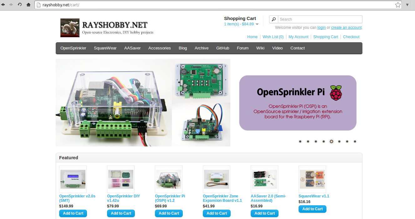
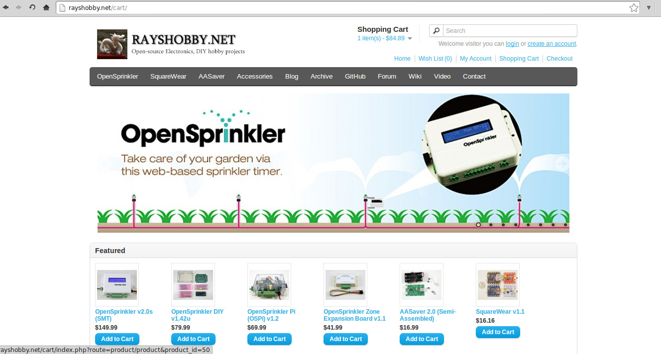
This is a quick heads-up that the new Rayshobby Shop Homepage is now available. The new page design is based on OpenCart, a popular free and open-source shopping cart software. It is fairly straightforward to set up, although I did spend quite some time creating nice looking graphics, including banners, product images, and product pages. The end result is satisfying. The shop page now looks much more professional with a load of new features. Take a look at these snapshots first:

rayshobby_newshoppage1

rayshobby_newshoppage

Before I started, I took a look at several options, including WooCommerce for WordPress, OpenCart, ZenCart etc. WooCommerce has the advantage that it integrates seamlessly with your WordPress blog. But it requires a theme that’s compatible with WooCommerce. Since I have an existing WordPress blog, I tried a few themes with WooCommerce support, and they don’t look that great: the images and formatting all become wacky. To fix them will require a lot of changes. So I’ve decided not to go that route. Regarding OpenCart and ZenCart, they both look great, I think OpenCart looks a bit simpler to set up and the design is more minimalist, so that became my pick in the end.

With OpenCart, it’s now a lot easier to add new products and keep them organized. Also, features like showing related products, applying coupons, comparing different products, managing user accounts, providing different payment options are automatically supported. Definitely a big step forward :). I have also added the distributor page to show current official distributors of OpenSprinkler products.

Of course, since this is a new system, I won’t be surprised if I’ve left some glitches. I will keep my fingers crossed and see how things go. If you see any problem or issue, feel free to let me know and I will get them fixed as quickly as I can. Thanks!

RI Mini Maker Faire Pictures

Yesterday we went to the RI Mini Maker Faire in Providence. I came back around midnight last night, feeling quite tired. It was a fun trip, and the first time that I went there as a maker. The faire was co-located with the Foo Fest, so even though its size is nowhere comparable to the Bay Area Maker Faire and New York Maker Faire, there were still a decent number of people. We had a single and fairly small table to showcase everything. As you can see from the pictures below, the table was very crowded, but we managed to lay out everything I wanted to show, and the promotional materials as well 🙂

As in previous Maker Faires, the most fun and rewarding part of the experience is that I get to talk to a lot of different people, explain to them how electronic gadgets work, get them excited about electronics, answer their questions, and hear their innovation ideas and solutions. I had two students, Kim and Cheni, who kindly offered their help, so I got to spend more time talking to people.

IMG_3025IMG_3021

IMG_3020IMG_3019

One tip I learned from the Bay Area Maker Faire earlier this year is that everyone is really excited about blinking LEDs. I know, it sounds trivial, but really, everyone loves it. Last time I just accidentally packed a hundred self-flashing and RGB color LEDs, together with coin batteries in my baggage. While setting up the table, an idea popped up in my mind that we can distribute them as free gifts at the faire. They are really cheap, so I don’t mind giving them away. What I didn’t foresee was how popular this was: the one hundred packets were gone almost in no time.

So this time, I am better prepared: I brought a bag of one thousand self-flashing and RGB color LEDs, together with one thousand batteries! We printed instructions so people can learn how to make an LED throwie on their own (basically sandwiching a coin battery in between the two legs of an LED). We distributed these as free gift to people, but told them it’s only free if they make one themselves (instead of taking away our demos 🙂 ) This was a huge success: I estimated that we gave away at least 250 of these. Many people passing by the table saw this and were eager to give it a try. Kids especially love these. Kim and Cheni were busy cutting tape and helping others learn to build their LED throwies. It’s really rewarding to see something so easy to learn can get people to excited, and it’s also fun to see how people were teaching each other at the table, and bringing their own friends to learn how to build these. Perhaps to some this will motivate them to explore the world of electronics. Then I will feel I have fulfilled my education mission a little bit 🙂

IMG_3034IMG_3035

Three months after its first prototype version, I am glad to announce that the long-awaited AASaver 2.0 has finally become available! In case you haven’t seen the first version of AASaver: it is basically a versatile boost converter that takes two AA (or AAA) batteries and bumps them to 5V so you can use it to power flashlight LEDs, or use it for breadboard experiments. The nice thing is that since it’s based on an efficient boost converter chip that has low start-up voltage, it can work with both new and used batteries. Even if the batteries can no longer work in other devices, like remote control, electronic toys, you can still use the AASaver to light up LEDs and run circuit board experiments for a long time. It’s a great way to harvest the remaining energy (or in layman’s term, suck the remaining juice) in your ‘dead’ AA batteries 🙂


The New Design

IMG_3016IMG_3011
IMG_3009IMG_3017
AASaver 2.0 is a completely redesigned circuit from its 1.x version. Here is a list of new changes:

  • Added USB port, which allows charging of USB devices such as mobile phones, MP3 players etc. To support up to 500mA charging current, the booster converter is changed to use NCP1450A, an upgrade from the previous MCP1640.
  • Added lithium battery charger (based on MCP73831), which allows charging of lithium polymer (LiPo) batteries from AA batteries. There is an on-board LiPo battery jack, and an SMT pot (trimmer) to provide adjustable charging current.
  • There is also an input LiPo jack, so the circuit can take source either from AA batteries or external LiPo battery. There is a good reason to provide this functionality, as explained below.
  • The original battery clips are changed to a plastic battery holder, which is mounted with screws on the back of the component side. This frees a lot of room on the component side, which in turn reduces the PCB size.
  • The breadboard pin headers are now changed to the battery holder side. The AASaver now takes much less space when plugged into breadboard. An additional pair of pinouts are also added to fit breadboards with extended width.
  • It’s also possible to use the circuit for solar charging, and charging LiPo battery from external USB port.

In sum, this version preserves the same basic functionality as before, which is to take two AA (or AAA) batteries and serve dual functions as an LED flashlight and breadboard power supply. But it also has a lot of new features and improved usability, most of which were adopted from user suggestions on the original version. Here is a quick summary of the spec:

  • Power Source: two AA/AAA batteries, or external 3.7V LiPo battery (selecctable by an on-board switch). Can also be modified to work with a single battery, or with a solar cell.
  • Power Output: any of the following: flashlight LEDs (seletable by a switch), breadboard pin headers, USB, or LiPo charger. The LiPo charging current is adjustable from 10mA to 200mA through an on-board trimmer.
  • Output Voltage: 5V up to 500mA.

Here is an annotated diagram for the various on-board components:aasaver2_diagram

Schematic and Board Design

Acknowledgement: the USB charging circuit, particularly the D+/D- line voltages, references the design of the MintyBoost by Lady Ada. Check the details about USB charging therein.

Technically AASaver 2.0 is different from the MintyBoost in that 1) it uses a different boost converter chip (NCP1450A vs. LT1302); 2) it has a built-in LiPo charger; 3) it uses SMT components and is mostly assembled. Also, AASaver is designed to be versatile and serve multiple functions, including LED flashlights, breadboard power supply, USB charging, and LiPo charging. Its primary goal is to make use of old batteries (hence the name AASaver 🙂 ).


The Kit

A limited number of the AASaver 2.0 kits are now available on Rayshobby Shop. More will become available in the upcoming weeks. Included in the kit are one assembled and tested AASaver 2.0 circuit board, battery holder, two pin headers, two bright flashlight LEDs, a power switch, two screws and nuts.

IMG_2982IMG_2981


Assembly and Usage Instructions

Although the circuit board is mostly assembled, it does require a few simply assembly and soldering steps to get it fully functional. If you’d rather not assemble and solder anything, you can order a completely assembled AASaver at additional cost. The instructions are posted below with high resolution images. These instructions will soon be posted on the AASaver homepage.

Step 1. Attach the Battery Holder

Use the two screws and nuts to fix the battery holder at the back of the PCB. Make sure that the battery holder wires are close to the side with the AA/LiPo Source Selector (i.e. the opposite side of the USB port).
IMG_2983IMG_2984

Next, cut the battery holder wires to about 1 to 2 inches long (don’t cut it too short, or otherwise you will have difficulty soldering it later). Then use a wire stripper to strip the lead, and then insert the wires to the PCB holes and solder them. Make sure that the red wire goes into the hole marked ‘+’, because this is the positive wire. Double check yours with the image on the right below.
IMG_2985IMG_2986

If you want, you can use a little bit of hot glue to fix the wires in place. This is not required, but is helpful as the wires are very thin and are prone to breaking if you wiggle them too much.

Step 2. (Optional) Solder the Breadboard Pin Headers and LEDs

Now you need to solder the breadboard pin headers and flashlight LEDs. NOTE: these steps are optional, and depends on what you want the AASaver for. If you don’t need it to run breadboard experiments, you don’t need to solder the pin headers (or you can always solder them later).

To solder the pin headers, first insert the two pin headers towards the end of a breadboard. This will help fixing them in place during soldering. Next, align the PCB holes on the AASaver with the pin headers. The height of the pin headers are designed to match the height of the battery holder, so if everything is correct, the battery holder should sit flat on the same surface with the breadboard. Note that this only works if the pin headers are inserted towards the end of a breadboard — if they are inserted in the middle of a breadboard, the battery holders will sit on top of the breadboard and this won’t work.

Also note that on the left side there is an additional pair of VCC-GND pin holes. These are designed for breadboards with extended width. So if your breadboard is wider than the one shown in the picture below, use the extended pair of pin holes.
IMG_2990IMG_2991

Next, to solder the flashlight LEDs, first insert the LEDs to the LED pin holes. These pin holes are located on the same side as the USB port. Make sure the longer lead of the LED goes into the hole marked ‘+’, as the picture below shows. Then gently bend the LED to 90 degrees, and solder the two leads. You can decide how long the LED should stick out of the circuit board, but in general, keep the LED close to the circuit board so that it doesn’t get accidentally bent. Once the LED is soldered in place, remember to cut the excessive leads. Follow the same process to solder the other LED.

IMG_2992IMG_2993

Now the AASaver is completely assembled! Below are the usage instructions.

Step 3. Power it On and Flashlight LEDs

Pop in two AA batteries. Make sure you insert them in the correct orientation. Then turn on the power switch. The red Power Indicator LED should light up. If not, check the Source Selector Switch, and make sure it’s turned to ‘AA’ (instead of LiPo In). The Source Selector allows you to select either AA or LiPo as the power source.

Next, turn Flash LED switch to ‘On’, and the two flashlight LEDs should light up. These are two bright flashlight LEDs, which work really well in the dark.

Note that the battery holder also sort of works for AAA batteries, although the contact is not very reliable. So if you want to pop in AAA batteries, try to use a small piece of aluminum foil to fill the gap between the AAA battery with the battery clips inside the holder. This should make it work perfectly.
IMG_2996IMG_3017

Step 4. Use it as BreadBoard Power Supply

AASaver is also designed to function as a breadboard power supply. It provides regulated 5V, which is great for many circuit board experiments. To use this function, simply plug the AASaver (with pin headers down) into a breadboard. Note that unlike the AASaver 1.x, the body of the AASaver 2.0 will stay out of the breadboard, so this gives you more room on the breadboard.
IMG_3009IMG_3011

Step 5. USB Charging

This is probably the most exciting new feature of the AASaver 2.0: you can now use it to charge USB devices. There is a built-in USB port that fits most standard USB cables. use it to charge your mobile phones, MP3 players, or anything that can charge through the USB port.

IMG_3001IMG_3016

Using a fresh pair of batteries, the circuit can provide up to 500mA charging current @ 5V output, which is sufficient for most USB devices. Also, empirical results show that with a fresh pair of batteries, you can charge the iPhone and the Samsung Galaxy S3 phone up to 20% to 25%. This is not a whole lot, but is good enough as an emergency charger, since AA batteries are really easy to get at convenience stores.

Now, there is a tricky question: since the hallmark of the AASaver is to save old AA batteries, can I use old or even almost ‘dead’ AA batteries for USB charging? The answer is mostly NO. Well, there is no magic: most USB devices require a certain amount of charging current in order to charge properly. Mobile phones are particularly power hungry. To provide 100mA @ 5V output, the AA batteries need to output at least (100mA x 5V) = 0.5 Watt power, and usually more to account for the non-perfect efficiency of the boost converter. Depending on the battery condition, you may or may not be able to draw that much power from a pair of AA batteries — for fresh batteries, no problem; for close to depleted batteries, almost certainly no. Technically, the problem with old batteries is that as soon as you start to draw higher current, the voltage of the battery will drop, and so the boost converter will start sucking more current from it, causing the voltage to drop further. At some point, the boost converter will not be able to maintain a regulated output voltage, hence it will stop charging.

What if you really want to dump the juice from old AA batteries to your phone? There is actually a solution, and you should keep reading below.

Step 6. LiPo Charging

In addition to USB charging, one of the new features of the AASaver 2.0 is LiPo charging. If you have a 3.7V LiPo battery (we carry an inexpensive 700mAH LiPo battery at Rayshobby Shop), you can plug it in to the LiPo Out jack. This allows you to charge the LiPo battery from AA batteries with an adjustable charging current (from 10mA to 200mA). Once the battery is charging, you should see the green Charge Indicator LED light up.

To change the charging current, use a small screw driver to gently rotate the trimmer (SMT POT). The trimmer is very fragile, so be careful when adjusting it. The flat side of the trimmer top is the tail, and the opposite side is the head. The charging current is indicated by where the head is pointing to.

How does the adjustable charging current help? As I described above, the issue with old batteries is that they cannot provide much output current. But they should still work if you ‘dump’ the power slowly. For example, they probably can’t provide 100mA output current at 5V, but they are probably good with 20mA current at 5V. So the trick is to dump the power slowly into a LiPo battery. This is analogous to having a water pipe with very limited capacity: you can’t draw water from it at a high speed, but you can let it drip slowly into a bucket (in this case the ‘bucket’ is the LiPo battery). Then later you can dump the water from the bucket at a much faster rate.

So all in all, if you have an old pair of AA batteries, you can’t charge USB devices directly. But you can still use them to charge a LiPo battery at a slow rate. To do so, adjust the trimmer so that the green indicator LED will remain on. If the LED goes off, it mean either the charge current is too high, or too low. So adjust the trimmer to keep it on. As you will see in the next step, with the LiPo battery, you can then charge USB devices with much ease.

IMG_2999IMG_3002

Step 7. Using LiPo Battery as Power Source

To use a LiPo battery as the power source, simply plug it in to the LiPo In battery jack, then make sure that you turn the Source Selector Switch up to point to LiPo In. This selects the LiPo battery as the power source, and everything else works the same way as before.
IMG_3000


All right, this is the end of the story. I know this post is very long, but most of it will be moved to the AASaver Homepage after I refine the text and hear back comments and suggestions from users. If you are interested, please place an order for the AASaver from the Rayshobby Shop. We have a limited amount right now and more stock will become available in the upcoming weeks.

Questions and comments? Post them below or on the Rayshobby Forum.


This is just a quick heads-up that we are heading to the RI Mini Maker Faire at Providence first thing tomorrow (Saturday) morning. If you are planning to visit the faire, make sure you drop by our booth to check out the latest gadgets, including the official OpenSprinkler v2.0s (with injection molded enclosure), OpenSprinkler Pi v1.2, all new AASaver 2.0 (blog post about this coming next), and the prototypes of OpenSprinkler Bee, OpenSprinkler Sip, and SquareWear 2.0. We will be selling physical products at the faire, and there is a small discount if you buy on site. Apologies for the lack of product updates recently, but more posts will follow after the Mini Maker Faier. Stay tuned!

opensprinkler_newrayshobby_businesscard

opensprinkler_v20sIMG_2982

First Try on Panelized PCBs

As I am getting more experienced with the TM-240A pick and place machine (in the following I will call it the PNP machine, as in PNP transistors 🙂 ), I’ve been thinking of ways to improve productivity. One obvious way is to panelize PCBs, meaning to assemble multiple copies of the PCB onto the same board. This can help greatly reduce the overhead time of stenciling and PNP loading time. I have to admit, I’ve never done PCB panelization before. I did search online and found various tutorials, but it’s unclear to me how to exactly indicate the ‘V-cut’ layer to the PCB manufacturer.

But I found an easier route. Recently I’ve been ordering PCBs directly from a Chinese company called ????? (http://www.sz-jlc.com). I got to know this company very randomly, actually through watching the beginning clip of the SparkCore Kickstarter video. The company has a very streamlined PCB manufacturing process, where you can track each step of the PCB making, all the way from drilling, to printing layers, to etching, to optical inspection, to solder-mask and silkscreen printing, to testing, and to shipping. It’s completely amazing (except the website only has Chinese version…). Anyways, when you order PCBs from their website, apparently you can specify how you’d like to panelize your PCBs. You don’t need to panelize the PCB yourself in Eagle (which I haven’t learned how to do yet), but you just need to describe your panel design (like 2×3, 4×4 etc.), and they will do the panelization free of charge. Isn’t that awesome?

Since this is the first time I’m ordering panelized PCBs, I wanted to be careful. So I ordered a very simple board — the OpenSprinkler Zone Expansion board, with the simplest panelization — 1×2. And the image on the left below shows what I received. Very neat. I also asked them to add an extra 10mm border on each side, and fiducial points (these I paid extra for). Since the board is not rectangular shaped, the panel comes with routed edges on the curved sections, and V-cuts on the straight lines. This way, it can be easily de-panelized by simply snapping each board off along the straight edges. Pretty awesome, especially considering I didn’t have to do anything in Eagle to create the panel design 🙂

IMG_0066IMG_0065

So what’s the picture on the right above? This is also something new to me: apparently when you order PCBs from the company, you can also order a laser-cut solder paste stencil to go with your PCB order. It’s only 10 extra bucks, almost a no-brainer. I ordered one for this particular batch, so I can experiment with it. The stencil is made from a steel sheet, and mounted on a metal frame. It’s quite large (37cm x 47cm), so you will need a stencil printing machine that can handle a board of this size. Fortunately I got a fairly big manual stencil printing machine a while back, so I can put it to good use now.

IMG_0067IMG_0069

In order to use the stencil, the first thing I did was to mount the stencil frame onto the printing machine. Once mounted, you can easily lift the stencil up and down, to quickly insert and take out stenciled PCBs. Then I aligned the PCB to the stencil holes. This is very tedious — since the stencil is made of steel, which is opaque, there is no easy way to align them. I had to do a lot of trial and error and eventually was able to get them perfectly aligned. Once aligned, temporarily fix the PCB in place by using some tape. Finally, use three old PCBs to make a frame around the center PCB. Then you are all set.

With the stencil printing machine (albeit manual), applying solder paste works like a charm, and is much faster than using my home-made stencils. The stenciling quality is also excellent (see the picture on the right below). Apparently they optimized the stencil design, and created small ‘crosses’ around relatively big (0805 or above) components. This prevents the solder paste from smearing underneath the stencil. Very smart!

IMG_0072IMG_0079

Next step is to populate components. The TM-240A pick and place machine supports PCB panelization. All that I had to do was to open the existing PCB configuration file, and add a new line for each additional sub-board, indicating the amount of shifting from the first sub-board. With this simple change, the PNP machine can now populate twice as many components, a real time-saver!

IMG_0074IMG_0076

Here are pictures of four boards before and after reflowing. The reflowing quality is pretty good.

IMG_0077IMG_0081

Finally, to separate the boards into individual pieces, as I said, just snap the boards along the V-cuts. Use some strength along the cuts, and they should come off pretty easily. Here are the final results (with the through-hole pin headers and screw terminals soldered in place). Neat, isn’t it 🙂

IMG_0082

So, to summarize, it takes very minimal effort to make panelized PCBs. First, when ordering PCBs, tell the manufacturer how you would like to panelize the board. They will do the work for you. Next, order a professionally made solder paste stencil with the PCB order. Finally, modify the pick and place configuration file to reflect the number of sub-boards and the shift amount of each. That’s it. Not bad at all!

« Newer Posts - Older Posts »