Feed on
Posts
Comments

Updates

  • Click here to see NeoDen 4 Pick and Place Machine with Vision System.

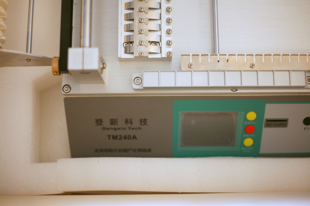
This is Part 2 of the NeoDen TM-240A pick and place machine demo. Today I placed the machine on a proper table downstairs in the basement, and had my first-hand results of a production run — namely using the pick and place machine to assemble the OpenSprinkler Pi circuit board. The results are pretty satisfactory. Here is a video demo:

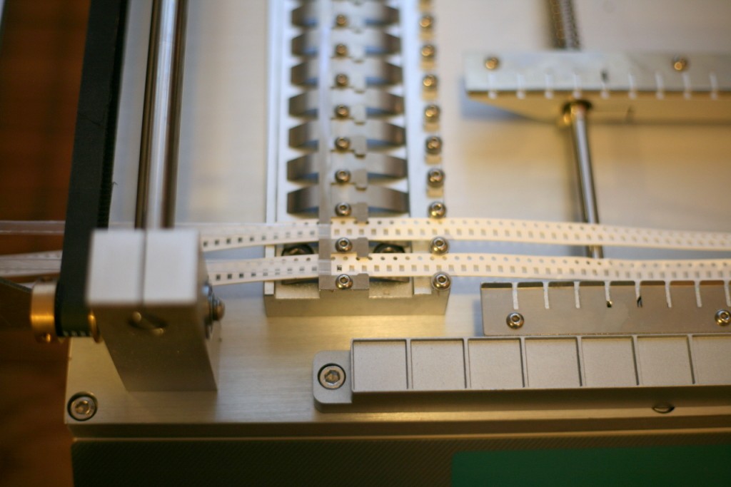
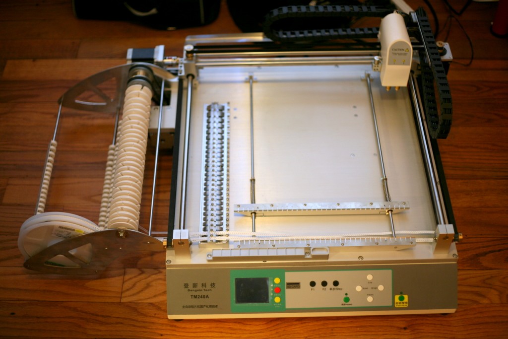
Now I will explain the boring details 🙂 The first step is to load the component tapes. The user manual has no instructions on how to load the tapes, so you have to carefully watch the videos provided by the manufacturer to learn. OpenSprinkler Pi is relatively simple so it doesn’t require many components. The TM-240A can fit twenty-one 8mm tapes, four 12mm tapes, and two 16mm tapes. While this is almost twice as much as its sister model TM-220A, the 12mm and 16mm slots turn out to be quite precious — those can easily run out and you will have to place the remaining components by hand. In my case, I also have a few relatively bulky components (e.g. LM2596S in TO263 package, and surface mount inductors and battery holders) that I have to place manually. So these components will all be hand placed after the machine pass.

On TM-240A, there is a front component loader that can fit 10 ad-hoc components. These can be bulky components that are not handled by the standard feeders. This is a very nice feature, however, the downside is that for each slot only allows one component, so you will have to re-load for each circuit board.

Next, I made a configuration file for the PCB. I started by using the Eagle script file downloaded from this link. I appreciate the author for sharing the script, as it saved me a lot of time of trying to figure things out myself. The configuration file is a human-readable text file and is very easy to edit. For example, for any components that I want to place manually, I simply put a value of ‘1’ in its ‘Skip’ column. Also, you can manually refine the x-y placement of each component based on the outcome of a trial run. You will probably have to sacrifice some components while tweaking the configuration file. To avoid wasting solder paste, I used the double sided tape that came with the machine, which allowed me to do trial runs as many times as I want. Once the configuration file is finalized, you can then switch to stencil printed PCBs.

Next, I applied solder paste to the PCB using my home-made solder paste stencil. I then placed the circuit board on the PCB holder of the machine. Make sure you push the PCB all the way to the left. Because my PCB is not perfectly rectangular, the machine’s origin is not aligned with the PCB’s origin. To fix it, I simply write down the amount of origin shift in the configuration file. The shift amount can be either calculated from the board design file, or can be measured empirically.

The exciting moment starts after clicking on the machine’s ‘Start’ button. It’s quite pleasing to see the machine moving quickly and precisely, picking up components and dropping them down on the circuit board. The machine can automatically detect if a component has been picked successfully (based on its internal pressure sensor reading), and make up to three attempts if it fails. The machine is also equipped with two needle heads. I installed a smaller needle, suitable for 0603 and 0805 components, as well as a bigger needle, suitable for components on the 12mm and 16mm tapes. The dual-head design is very convenient, as I basically never have to change the needles any more.

With less than 20 components to place, the machine finishes each pass very quickly. From the video you can see that a few components are not aligned perfectly, but these present no problems at all for the reflow process. Indeed after reflowing, most components will get aligned well with the solider pads. Well, to be fair, I’ve used mostly large components (e.g. 0805), and have yet to try smaller components. So I can’t say if the accuracy is sufficient for boards mostly populated with 0402 components. But I am pretty sure 0603 should be all right.

Anyways, I hope the video has given you some ideas of the capabilities and limitations of this machine. The next steps I would like to try include adjusting the speed of the machine to see if that helps with the placement accuracy, paneling the PCB to improve productivity, and also try to use the front loader for some of the bulky components. Feel free to leave your questions and comments below. Thanks!

One of the hallmarks of OpenSprinkler / OpenSprinkler Pi is the capability of expanding the number of zones. While the main controller can only interface with 8 zones, you can expand beyond 8 zones by daisy chaining Zone Expansion boards. Each expansion board adds another 8 zones. Because the zone expansion is implemented using shift registers, there is no hardware limitation on the total number of zones (although there is a software limitation due to the memory space required to store the information and data for each zone). This provides an economic way to implement a large number of zones. On commercial sprinkler controllers, zone expansion is relatively expensive, sometimes requiring you to upgrade to a new controller all together. On OpenSprinkler, if you need more zones, just buy more expansion boards. The software is designed to handle all zones in a consistent user interface.

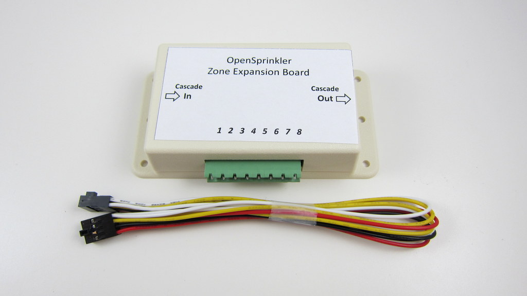
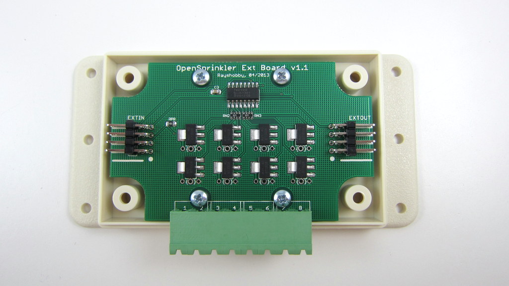
Previously, the zone expansion board is based on the same PCB as the main controller, and they share the same enclosure. This makes it easy to use a consistent enclosure design for both. However, the zone expansion circuit is actually very simple (just a shift register, a couple of resistors, and eight triacs), so it’s no need to commission a PCB as large as the main controller for something that can be much smaller. So I’ve decided to give the expansion board an upgrade, to version 1.1, which uses a much smaller PCB footprint, and its own dedicated enclosure (based on Serpac WM011).

IMG_3017IMG_3014

The new version is just a little over half the size of the original one. So in the same amount of space you can almost fit two expansion boards. This is particularly useful for people who has a limited space to fit a main controller and one or more expansion boards.

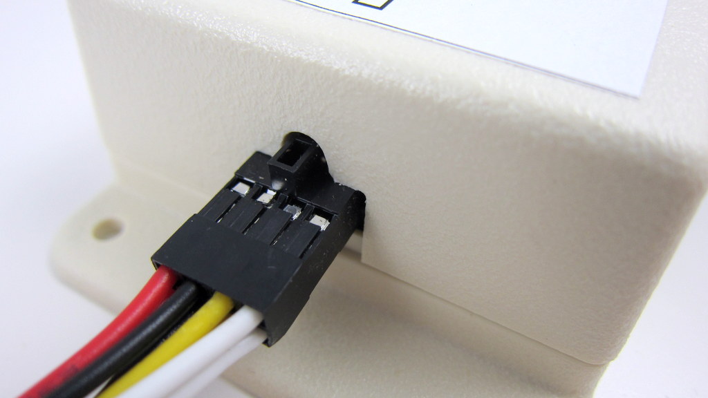
In addition, the zone expansion cable has been upgraded to use a polarized connector. Specifically, the connector has a small bump at the top, which matches the notch on the cutout of the enclosure. This way, there is only one possible orientation to insert the cable connector, thus preventing incorrect orientation:

IMG_3011IMG_3013

The picture on the left above shows the polarized cutout on the expansion board, and the picture on the right shows a similar cutout on the upcoming injection molded OpenSprinkler enclosure. This can help avoid mistakes when inserting the expansion cable. A special note that this cable has different pin connections with the previous version of expansion boards. So you should NEVER use the polarized cable with previous versions of zone expansion boards, or you may risk damaging your main controller!

Finally, expansion board v1.1 has added a 10K pull-down resistor, which when coupled with OpenSprinkler 2.0, allows the main controller to automatically detect the number of zone expansion boards. This feature is already included in hardware design, but hasn’t been implemented in software yet. The basic principle is that the main controller has a 1.5K pull-up resistor, and each expansion board has a 10K pull-down resistor. When multiple expansion boards are linked together, the pull-down resistors are connected in parallel, thus changing the divided voltage. By using an analog pin (which is internally wired to the voltage division point), the controller can easily calculate how many boards are linked together. A very simple solution!

To conclude, here is a short summary of the new features on OpenSprinkler Zone Expansion Board v1.1:

  • Reduced form factor, and dedicated enclosure.
  • Polarized expansion cable connector.
  • Added pull-down resistor for automatic detection of the number of expansion boards.
  • Besides, the new expansion board retains the on-board PCB holes to fit one MOV per zone, and it works with both OpenSprinkler and OpenSprinkler Pi.

That’s all for the update. This new version is in stock and available for purchase at Rayshobby Shop. Same old price!

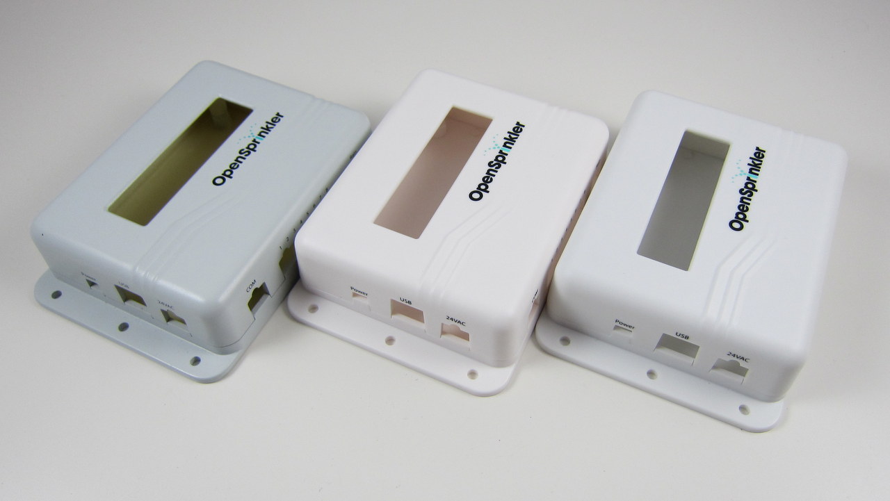
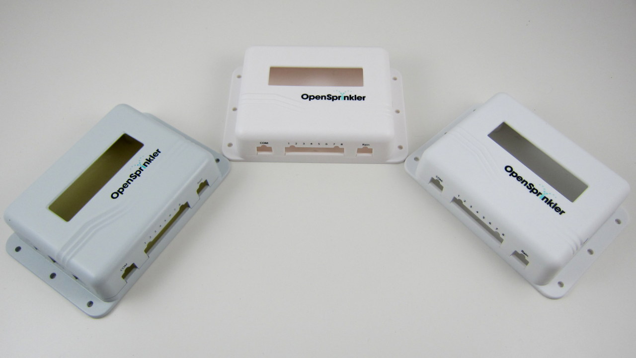
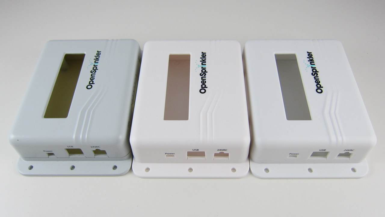
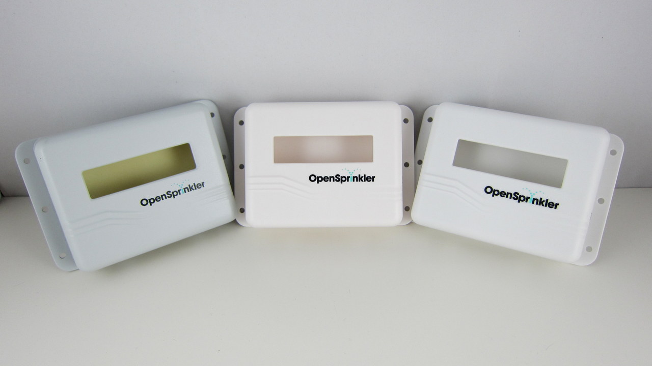
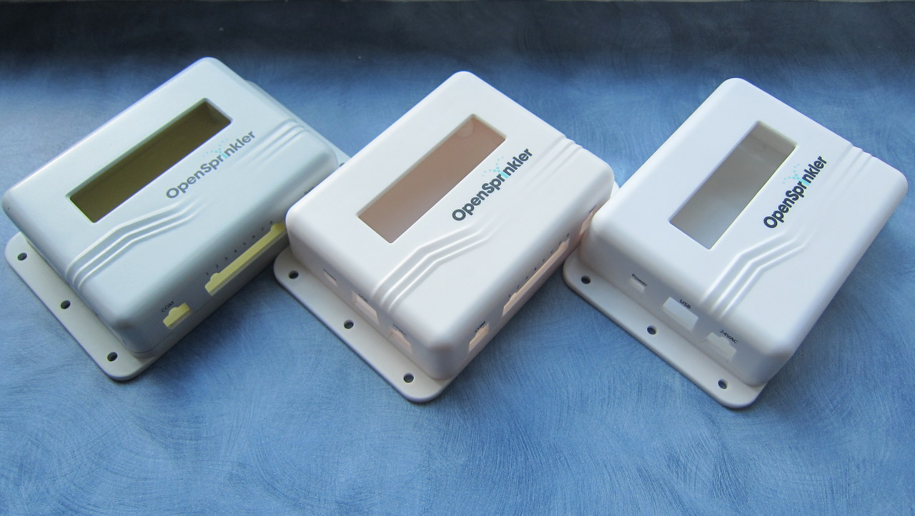
The final sample of the injection molded enclosure has arrived. Very exciting! The moment of decision: I’ve got three samples, each with a slightly different color. I’ve taken a few picture of all three side by side. The differences are subtle, but basically the first one (left) is more gray-ish, the second one (middle) is closer to milk white, the third one (right) is closer to pure white. Please vote for your favorite color in the comments section below (you can either use 1, 2, 3, or left, middle, right, or anything un-ambigious). I’ve only got a couple of days to give them my final decision, so please vote as quickly as you can. Thanks!

IMG_3003-001

IMG_3006-001

IMG_3005-001

IMG_3004-001

IMG_3000-001

Updates

  • Click here to see NeoDen 4 Pick and Place Machine with Vision System.
  • Click here to see Part 2 of the TM-240A video.

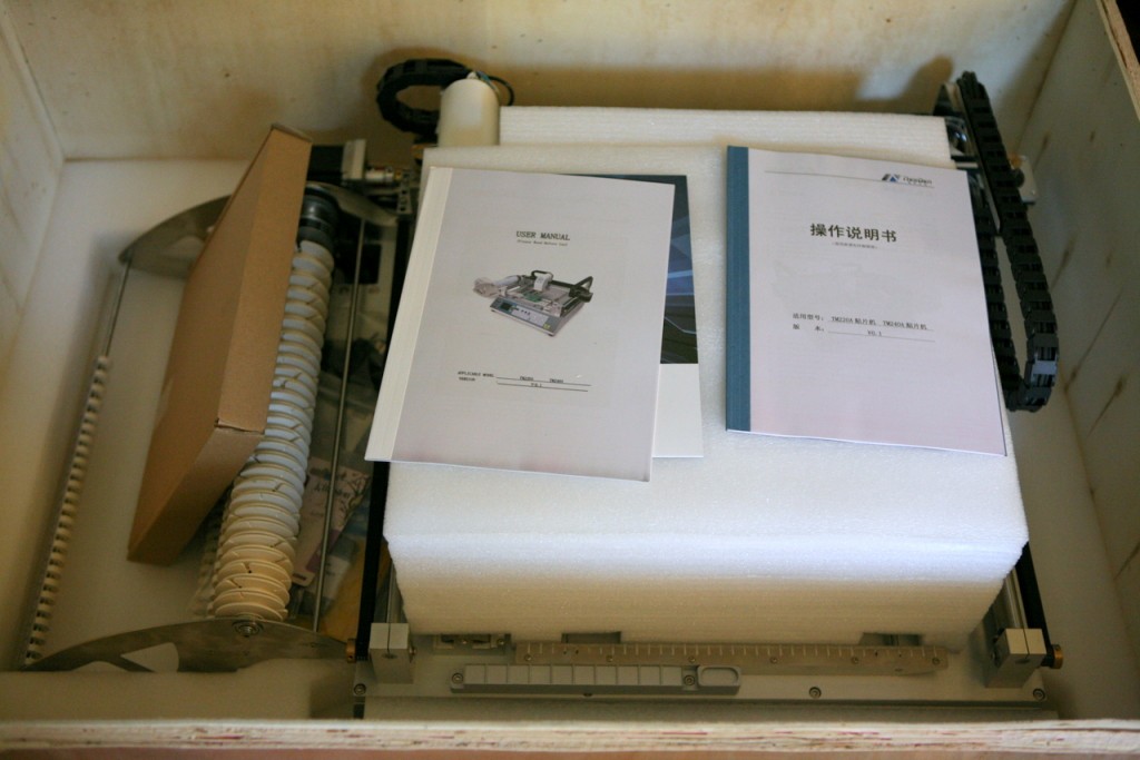
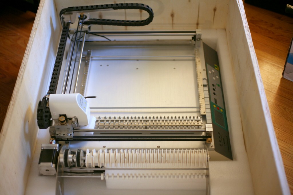
Yes, there have been lots of new updates recently. Among them is a new toy I received in the mail today: a NeoDen TM-240A automatic desktop pick and place machine! I’ve kept my eyes on this baby for a quite a while, and finally decided to make a purchase last week. The shipping was very fast: DHL from China, a total of 4 days from shipping to delivery. The package is quite heavy: 65kg with the box, and 45kg just the machine itself. The DHL courier and I moved it together to my workshop. Some unboxing pictures:

IMG_2664IMG_2668IMG_2671IMG_2672

So what’s a pick and place machine? Simply speaking, it’s a machine that can quickly and accurately place SMT components onto a PCB. As our orders keep increasing, we need better tools to significantly improve the manufacturing productivity. It’s true that the major manufacturing needs can be outsourced to companies like SeeedStudio, but you will always have to prepare for unexpected delays. Also, small production runs are not worth outsourcing to China. So it’s crucial to have in-house manufacturing capability to meet small production needs.

The basic tools for small-scale PCB assembly include a stencil printing machine, a pick and place machine, and a reflow oven. The pick and place machine is probably the most expensive among the three. The NeoDen TM-240A is a relatively low-cost model. It’s desktop-size, so it’s light-weight and doesn’t take a huge amount of space. It has built-in suction pump, 28 feeders, two placement heads, speed of 7000 components per hour, and a maximum PCB area of 400mm x 360mm. It costs about $5000, which is significantly cheaper than machines at similar specs. I’ve seen machines that cost at least 10K, and even at that price you have to buy feeders separately. There is a sister model to TM-240A, which is TM-220A. It’s cheaper (~$3600), but with less feeders and smaller PCB area. The downside of TM-240A is that it does not have a vision-based system, so it’s not as accurate as the more expensive machines. But considering its price and capability, I decided it’s a good investment.

IMG_2675IMG_2674

I bought the machine directly from the Chinese website Taobao, which is the equivalent eBay in China. Shipping is 3000RMB (~$490). Considering it took only 4 days from China to the US, it’s not a bad price. All together I paid about $5500, including the machine and shipping cost.

As soon as I got the machine, I couldn’t wait to open it and give it a try. The user manuals are pretty minimal, but there is an SD card that contains several tutorial videos which are very helpful. For example, the user manual does not explain how to install the component tapes, and it took some careful watching and rewinding of the tutorial video to figure it out. The package came with a sample PCB and a bunch of double-sided tape. Using these I could quickly set up a test run without applying solder paste at all. The video below shows a demonstration. It’s very exciting to see the machine in action! It’s also quite fast. I am looking forward to using this machine in real production. I am glad that this machine has sufficient number of feeders to handle OpenSprinkler in one pass (i.e. no need to change tapes in the middle). There will be quite a bit of learning involved, but I am hopeful 🙂

Update: Click here to see Part 2 of the video.

After a few weeks of shipping these ‘underground’, I am finally happy to spread the words around: the OpenSprinkler Pre-Release v2.0s is officially available for sale! Note that this is the SMT assembled version — we don’t have DIY 2.0 yet. As usual, the first question to ask is what’s new in this version?

  • Upgraded MCU: OpenSprinkler 2.0 uses ATmega644, which is twice as much as ATmega328 in all aspects (i.e. flash memory size, GPIO pins, RAM, EEPROM, perhaps price as well 🙂 ). This makes it possible to add new features that I have planned ahead (e.g. weather-based control, logging, interfacing with wireless devices etc.) We will no longer be constrained by the flash memory size, well, at least for a while.
  • Upgraded Switching Regulator: the switching regulator (for 24VAC->5VDC conversion) has been upgraded from MC34063 to LM2596, which is less noisy and capable of outputting higher current. As more users are powering WiFi adapters through OpenSprinkler’s USB port, it’s important to make the power conversion section robust. The same circuitry is now also used in OpenSprinkler Pi. Details about this change can be found in this blog post.
  • Added microSD Card Slot: microSD card is useful for expanding the storage size of a microcontroller. This s great for a lot of purposes, such as logging, storing a lot of sprinkler programs, Javascript files etc. A standard microSD card shares the SPI interface and requires only one extra GPIO pin to operate. Hence adding microSD card support is a no brainer!
  • Expansion Board Detection: this allows the main controller to automatically detect the number of zone expansion boards linked to the controller. Not so crucial, but neat. The implementation is actually quite simple: it uses a pull-up resistor on the main controller and one pull-down resistor on each expansion board to form a voltage divider. By checking the voltage using an analog pin, the mcu can easily calculate how many boards are linked.
  • Other Features: given the plentiful GPIO pins available on ATmega644, I’ve added support to adjust LCD contrast and backlight (using two PWM pins), a set of pin headers for plugging in an off-the-shelf RF transmitter (for interfacing with wireless devices). The other un-used pins are made available in the pinout area (including three analog pins, two interrupt pins, two digital pins, as well as TXD, RXD, SDA and SCL).

OK, that’s quite a detailed list of new features. Here is an annotated diagram of the actual hardware:

os20_component_diagram

Also, just for fun, a diagram that shows each module of the circuit and where they are located on the PCB:

os20_module_diagram

The reason I call this the Pre-Release 2.0 is that the official 2.0 will use the injection molded enclosures I blogged about in this post. While that is already in production at SeeedStudio, I can’t give a reliable estimate of how long it will take for the final products to arrive. There have already been multiple delays, so I won’t be surprised if there are more… Other than the difference in the enclosure design, the pre-release 2.0 hardware is the same as the final 2.0.

If you are wondering what I mean by ‘shipping these underground’ at the beginning of the post — we’ve been automatically upgrading the recent orders of assembled OpenSprinkler v1.4s to v2.0s. Why not make it public? Well, there are several reasons. The first is that due to the Maker Faire and the vacation after that, I haven’t had time to finish the documentations, and I’m reluctant to officially release a product when the documentations are not ready yet. Second, I’ve been experimenting with minor changes of the 2.0 design, and we’ve been shipping several small batches, each with slight different hardware design. This is an important process to get user feedback, and to iron out all engineering issues before the official release. Finally, as many users have been waiting for 2.0, I don’t want to suddenly get into an overload situation, where the number of orders exceed our capacity to process them.

In terms of software, OpenSprinkler 2.0 is currently flashed with firmware 2.0.0, which is functionally the same as firmware 1.8.3, except for the additional options such as LCD contrast and backlight, and the support for a higher number of expansion boards and programs. More exciting firmware features will be gradually added over time. Also, starting from firmware 2.0.0, the source code can be compiled in Arduino 1.x (latest stable version is 1.0.5), and this is also the recommended Arduino version to compile OpenSprinkler code. I will continue to provide a VirtualBox image which has everything needed for compilation set up and ready to go.

The final bit of news: if you are interested in DIY 2.0, unfortunately that won’t be available for at least a couple of months. The delay is partly because the new injection molded enclosures are not ready yet (there is no space in the current enclosure to fit all through-hole components), and partly because there are a few design decisions I haven’t ironed out yet. So at least for a couple of months we will keep offering DIY 1.42u for anyone who wants to build OpenSprinkler from scratch.

So much for the announcement of OpenSprinkler Pre-Release 2.0. Feel free to leave your comments and suggestions below, or at the Rayshobby Forum. Thanks!

« Newer Posts - Older Posts »