Feed on
Posts
Comments

Check my new blog post on the ESP8266 Serial-to-WiFi module


As the Internet-of-Things (IoT) are becoming more and more popular, there is an increasing demand for low-cost and easy-to-use WiFi modules. For Raspberry Pi and BeagleBone, you can plug in a cheap USB WiFi dongle (like the popular Edimax 7811). These dongles are generally less than $10. But for microcontroller-based devices, the options are much fewer and generally more costly. For example, an Arduino WiFi shield can easily cost $40 to $50; even the more recent CC3000 module costs about $35. If you are puzzled by the big price difference: those cheap WiFi dongles require a USB host system, which is beyond the capability of Arduino. Still, it’s unsettling to realize that a WiFi module or shield would cost more than an off-the-shelf WiFi router, even though the router is significantly more powerful.

Recently I saw a post on Hack A Day alerting us about a new Serial-to-WiFi chip. I immediately ordered two of those. I honestly don’t know what I should expect from these $3 parts, but perhaps it’s a good push towards a new wave competitions on low-cost WiFi solutions. Anyways, while waiting for the shipment to arrive, it reminded me that a while back I actually bought something similar: a Hi-Link HLK-RM04 Serial-to-WiFi module. It’s about $10, so still pretty low-cost. I am glad I didn’t lose it, so I took it out of a pile of electronics and started experimenting with it.

IMG_0222IMG_0221

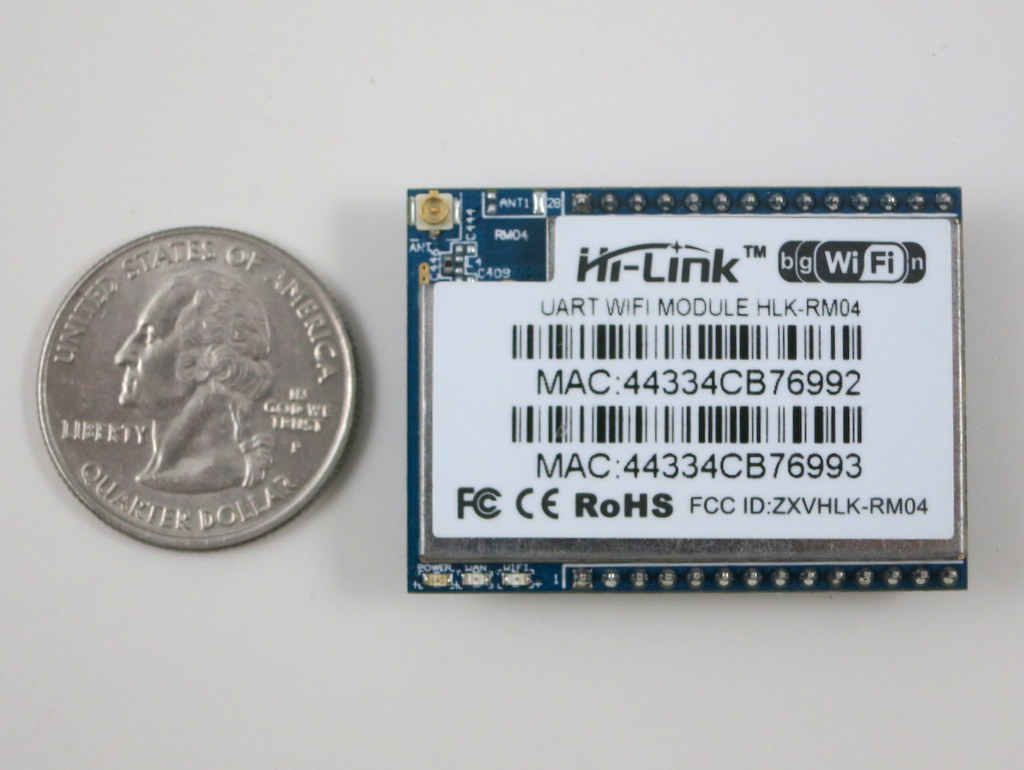
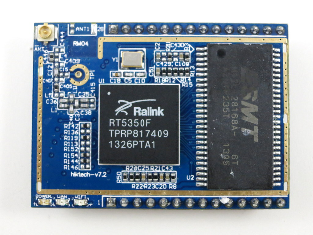
As you can see, the module is pretty small (about 40mm x 30mm). The picture on the right above shows the components underneath the metal shield. The chip (RT5350F) is a 360MHz MIPS core with built-in WiFi support. The module is quite powerful — at factory default settings it functions as a normal WiFi router. Now, in order to get it to talk to a microcontroller like Arduino, I need to use its Serial-to-WiFi capability. What is that? Well it means using the serial (TX/RX) interface to send and receive Ethernet buffers, and similarly using serial to send commands to the module and query or change its current status. This is quite convenient because first, it only takes two wires (TX/RX) of the microcontroller to talk to the module, second, it moves WiFI-related tasks to the module allowing the Arduino code to be very much light-weighted.


Check my new blog post on the ESP8266 Serial-to-WiFi module


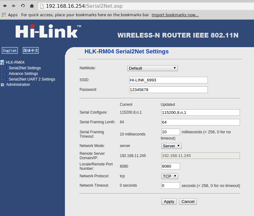
Power-Up. To start the module you just need to provide +5V power. At the first use, the module boots up into a WiFi AP (access point) named Hi-Link-xxxx so you can actually log on to the WiFi network and change settings there. Here is what the homepage looks like (default IP: 192.168.16.254, default log-in: admin/admin):

hlk_rm04_1

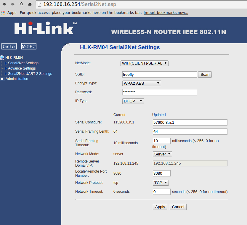
Change Settings. For my purpose I need to set the module as a WiFi client so that it can log on to my home network, and allow the Arduino to communicate wirelessly through the module. So I changed the NetMode to WiFi Client – Serial, and put in my home network’s SSID and password. I also changed the Serial baud rate to 57600 (the default is 115200): the lower baud rate can help Arduino to communicate with it more reliably especially if I am going to use software serial. Make sure that the Local/Remote port number is set to 8080 or anything other than 80 (because 80 is reserved for the module’s homepage).

hlk_rm04_2

Receiving Data. Now after the module boots up, it appears as a device on my home network (for example, 192.168.1.147). If I type in 192.168.1.147 in a browser, I will still see the same homepage as above. However, now I can communicate with the module’s serial interface through port 8080. To see what’s going on, I used a PL2303 USB-serial converter: connect the serial converter’s +5V, GND, TXD, RXD to the WiFi module’s +5V, GND, RX, TX (note TXD->RX and RXD->TX), then I opened a serial monitor at 57600 baud rate (putty in Windows or gtkterms in Linux). Now type in http://192.168.1.147:8080 in a browser, I get the following output on the serial monitor:

GET / HTTP/1.1
Host: 192.168.1.147:8080
Connection: keep-alive
Accept: text/html,application/xhtml+xml,application/xml;q=0.9,image/webp,*/*;q=0.8
User-Agent: Mozilla/5.0 (X11; Linux x86_64) AppleWebKit/537.36 (KHTML, like Gecko) Chrome/37.0.2062.94 Safari/537.36
Accept-Encoding: gzip,deflate,sdch
Accept-Language: en-US,en;q=0.8,zh-CN;q=0.6,zh;q=0.4

Cool, this means the Ethernet buffer has been received through the serial RX pin. If I can then send something back through the serial TX pin, like acknowledgement plus HTML text, the data will be transferred back to the browser. This is basically how HTTP GET command works.

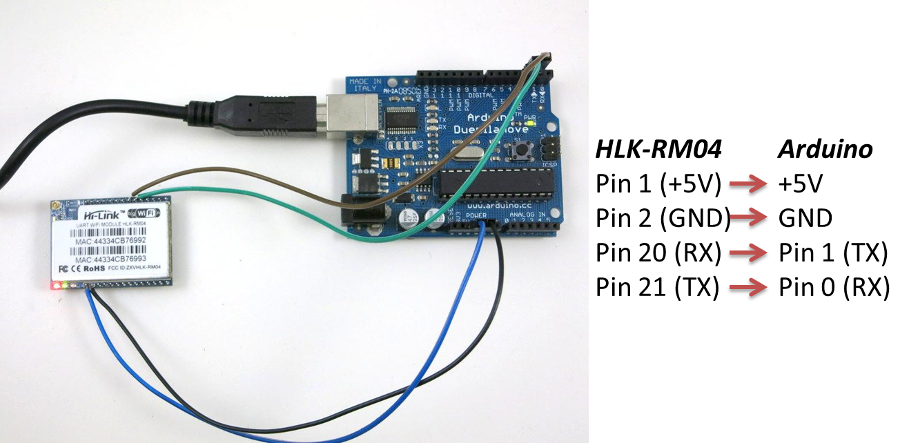
A Simple Arduino Example. To send data back through the serial TX pin, I used an Arduino to set up a simple example. To get reliable communication, I used Arduino’s hardware RX/TX (0/1) pins. The drawback of this is that when you program the Arduino you need to temporarily disconnect the WiFi module from these two pins, otherwise they will interfere with the uploading process. Here is a picture of the setup:
hlk_rm04_3

Next, I wrote an Arduino program to print out the analog values of A0 to A5. This is actually modified from the WebServer example in the Arduino Ethernet Shield library:

void setup() {                
  Serial.begin(57600);
}

void loop() {
  boolean has_request = false;
  if (Serial.available()) {
    while(Serial.available()) {char c = Serial.read();}
    has_request = true;
  }
  if (has_request) {
    Serial.println("HTTP/1.1 200 OK");
    Serial.println("Content-Type: text/html");
    Serial.println("Connection: close");  // the connection will be closed after completion of the response
    Serial.println("Refresh: 5");  // refresh the page automatically every 5 sec
    
    String sr = "\n";
    sr += "

Basically receiving/sending Ethernet buffers is done through reading/writing into serial. Now open a browser and type in http://192.168.1.147:8080, I see the following:

analog input 0 is 521
analog input 1 is 503
analog input 2 is 498
analog input 3 is 510
analog input 4 is 525
analog input 5 is 548

Pretty cool, isn’t it! ๐Ÿ™‚ If I have a SD card connected to Arduino, I can also serve files, such as Javascripts or logging data, from the SD card.

Blinking LEDs. By analyzing the received buffer, I can also implement various HTTP GET commands. For example, the program below sets the LED blinking speed by using http://192.168.1.147:8080/blink?f=5 where f sets the frequency.

void setup() {     
  Serial.begin(57600);  
  pinMode(13, OUTPUT);
}

int f = 0, pos;
void loop() {
  boolean has_request = false;
  String in = "";
  if (Serial.available()) {
    in = "";
    while (true) {  // should add time out here
      while (Serial.available() == false) {}
      in += (char)(Serial.read());
      if (in.endsWith("\r\n\r\n")) {
        has_request = true;  break;
      }
    }
  }
  if (has_request) {
    int i1 = in.indexOf("GET /blink?f="), i2;
    if (i1 != -1) {
      i2 = in.indexOf(" ", i1+13);
      f = in.substring(i1+13, i2).toInt();
    }
    Serial.println("HTTP/1.1 200 OK\nContent-Type: text/html\nConnection: close");
    String sr = "\n";
    sr += "\n";
    sr += "LED frequency: ";
    sr += f;
    sr += "Hz.";
    Serial.print("Content-Length: ");
    Serial.print(sr.length());
    Serial.print("\r\n\r\n");
    Serial.print(sr);
    has_request = false;
  }
  if (f>0) {
    static unsigned long t = millis();
    if (millis() > t + 1000/f) {
      digitalWrite(13, 1-digitalRead(13));
      t = millis();
    }
  }
}

More on Changing Settings. Instead of using the WiFi module’s homepage to configure settings, you can also change settings by sending serial commands to the module directly. This can be done by pulling the RST pin on the module low for a couple of seconds, which switches the chip in AT command mode. Then you can send (through serial) any of the listed AT commands to change parameters such as SSID and password. This is a nice way to add some automation to the configuration process. Details can be found in the module’s datasheet.

Drawbacks. The main drawback of a Serial-to-WiFi module is that the data transfer speed is quite low. I tested transferring a file stored on SD card and am only getting 5 to 7 KB/s. This means to transfer a 1MB file it will take 3 minutes. Clearly not a good solution for bulk data. Another drawback is that if you need to restart the WiFi module it generally takes 35 to 50 seconds to boot up, that can be an issue for the impatient. Fortunately you likely don’t need to reboot the WiFi module frequently.

Overall the HLK-RM04 Serial-to-WiFi module is a reasonable and low-cost solution for adding WiFi to Arduino and similar microcontroller boards. At the price of $10, there is no much more you can ask for ๐Ÿ™‚

52 Responses to “First Impression on HLK-RM04 Serial-to-WiFi Module”

  1. Martin Ayotte says:

    Interestingly, and per pure coincidence, I was looking at some cheap WiFi solutions too since few weeks. I’ve purchased a CC3000 more than a month ago, but also one HLK-RM04 few weeks ago, and also more recently one USR-WIFI232-G2.
    Unfortunately, I faced a bug with the CC3000 : it hangs once in awhile, usually in less than 10 hours of stress test (http request once avery 5 secs). (TI will loose this IoT market if they don’t fix that bug soon. Many folks faced the same issue, even the SparkCore users. Some prays that the newer CC3200 will be better)
    I didn’t get such issue with the HLK-RM04, so I like it pretty much.
    Today, I’ve start the same tests with USR-WIFI232-G2, I will watch for it reliability too.
    The main advantages of this last one are : a bit smaller (although more difficult to solder wires), it is cheaper, but also it can be used in both AP and STA mode at the same time (I think it has 2 WiFi channel)

  2. Saulius says:

    Interesting, cheap but useless thing. SSL – not found, Complex protocols – not possible, Security – none. C’mon – it’s a toy. Better look at Carambola2 from 8devices.

    • John says:

      that’s a ridiculous conclusion. Comparing simple URAT-to-WiFi converter with a SoC device makes no sense. Smells like someone’s disgracefully promoting own product.

  3. Ari S. says:

    I have been playing with this module also and I think it’s quite nice for the price. I managed to use it as a ethernet-like wifi module for uIP stack so that tcp/ip stack runs on my microcontroller and rm04 module only takes care about wifi stuff.

    Details are at http://stonepile.fi/wifi-for-picoos-net-uip/

    I was also thinking about using CC3000 module before, but that would have meant that I would have to toss away all the work already done with uIP stack. I wish that hlk-rm04 had more memory, that would make it even more versatile module.

    Pin spacing of the module is not breadboard-friendly (2 mm instead of 0.1″).

    • Martin Ayotte says:

      Yes, Squonk !
      I’m following all thoses thread too. The ESP8266 start appearing on eBay, I’ve ordered mine this morning (but it will take 3 weeks).
      BTW, congratulations for all the work that have been done in few days for ESP8266. I wish to participate soon if I can.

  4. […] project can simply send serial data to it using the TX and RX pins. RAYSHOBBY.NET has a great tutorial including code to get you started with this […]

  5. Ranjoy says:

    Hi Ray,
    Hope you are doing well. Was searching for a low cost wifi shield for arduino and landed to your page. Looks pretty cool :-).
    My requirement is to capture all the devices mac id and rssi value in range to the arduino device.
    The devices may not be connect to the router. I saw scanNetwork function of arduino wifi shield. Will this device solve my problem
    Can you kindly help me out.

    Ranjoy

  6. Ali says:

    Hi Ray,

    Thank you very much for this helpful article.
    It helped me a lot to set up my system fast and trouble-free.

    Good luck,
    Ali

  7. Gautam says:

    Hi Ray,

    Thanks for the article.
    I want to setup a master with two client nodes. All three nodes are to be controlled by microcontrollers. How to send & receive data to the master node from the client nodes through WiFi?

    Regards.

    Gautam

    • ray says:

      Maybe you can set the master in AP mode, and the other two in client mode, that way the two clients can connect to the master AP and communicate with it.

  8. ben says:

    This module looks the same as asiarf, including the use of ralink5350.
    https://www.indiegogo.com/projects/asiarf-tiny-linux-computer-with-wifi-and-ethernet

    Since asiarf supposedly can run openwrt, I wonder if the hilink module can too!

  9. Drake says:

    You’re running the GPIO pins at 5.0v? The data sheet says 3.5v is max GPIO voltage. Thanks!

    • ray says:

      I just checked the datasheet, you are right, the GPIOs are only rated 3.5V max. I guess they are 5V tolerant in practice after all. But in any case, should add a series resistor and 3.3V zener on the RX pin of the WiFi module.

      • Drake says:

        I’m currently running this unit for a project. It’s held up for 5V now for dozens of hours, thought I’m only sending very short messages via software serial every 90 seconds. I’m a bit worried about using a voltage divider or similar setup – as I understand it they can potentially lead to instability.

        Tonight I’m ordering a stack of cheap 3v3/5v logic levels just to make sure I have a reliable device. (Who doesn’t need a stack of bidirectional logic levels sitting around anyway? You never know when you’ll need them.)

        Thanks for the post on this product.

  10. zainab says:

    Thank for useful information l need to rest HLK-RM04(uart wifi module ) because I do steps in github web site but in wrong way ,I uploade in bootloader (uboot128.img)
    Then the module not respond and not appear in wifi list
    Please help me to rest

    • ray says:

      Well I think you will have to reflash the module with the correct firmware.

      • roxana says:

        Hi,

        Im an electronic engineer and its the first time that I use wifi devices. I set Hlk-rm04 in client mode and then i changed the IP address. and now I can neither open the webpage nor connect to the module. would you please help me to reset to flash the module?

        Bests,
        Roxana

  11. mohsen rahmani says:

    Hi,
    I want to connect wifi module (RM04) in celint mode to an access point.
    so i need to define NetMode :Cliect and NetworkMode :client and define a remote port to conncet to it.
    module(RM04) can connect AP but socket can not open to transrecive data?
    can you help me?

  12. Haribabu says:

    Hi

    I also bought one of HM04 MODULE with RS232

    Set up as 192.168.16.254 and network mode as Wi-Fi AP to Serial
    It is connecting to my laptop but unable to receive any thing
    On serial port typed 192.168.16.254:8080/
    Am I missing anything?

    If I select network mode other than the above it is not connecting to laptop via Wi-Fi

  13. Anthony says:

    Hi Ray,
    Hope you are ding well.First of all I would like to thanks for the article.

    I had a problem with the device. I follow your steps according to the article. all the first steps were ok, but after I change my home networkย’s SSID and password in wifi app., my laptop didn’t recognized the device. can you please help me I’m doing my final year project.

    At the beginning I Set my laptop to static IP mode. There I set the IP
    address to 192.168.16.100/255.255.255.0, gateway 192.168.16.254

  14. Haribabu says:

    Hi
    I was wrongly connected the serial Tx and Rx.
    It is working fine

  15. dan says:

    Hi, i’ve bought this serial to wifi module some days ago.
    I cannot find how to use the integrated Gpio pins… is there a way to use them without connect a microcontroller like arduino?!
    i would like to read the state of gpio (on/off state or even temperature sensor etc) pins from my pc/mobile via http page or send the data to a pc/raspberry/arduino that collect them and put into a web page.

    • ray says:

      I’ve never tried to use the GPIO pins. I think that requires changing the firmware (unless if the stock firmware has a secret feature that allows you to use the GPIO pins). By default it’s just a WiFi-to-Serial module, and you will need a microcontroller if you want to switch pins.

  16. Dmitry says:

    I use something like this, it’s name “High Fly HF-LPB100”. It communicates with Infineon XMC4500 (32 bit 120MHz embedded ยตc) at 1 Mbit baud rate! Totally cool!

  17. Sheve says:

    Hi, I faced a problem when booting this Wifi Module, there should be a built in configuration pop up during the booting but the module do not give any respond to me. Is there any procedures or steps necessary to follow to boot it? If got can you help me in this by showing me the steps. Thank you.

    • ray says:

      Try to do a reset and see if it works. It may also be that the firmware that comes with your module has removed this initial setup. If you can find documents associated with your module, look for information there.

  18. murat says:

    I want to use msp430f5529 instead arduino. how can ? do?

  19. bel project says:

    hi everybody,
    ray mentioned that when i connect the HLK rm04 module for the first time the Access point automatically pops up. However in my case when i connect the wifi module to arduino(merely for power supply of +5v) nothing of this sort happens. i tried punching in the ip address of 192.168.16.254 but i shows “Connection time out”.
    can someone help me out with this?

  20. Nick says:

    How can I use this as a client to send a http GET request (in Serial to WIFI CLIENT-dynamic ip mode)?? can I use TX RX pins with arduino for this?

  21. Neo says:

    very well try;
    actually I have done some amazing task with this tiny module,but had a bigger Idea,and I’m not sure whether or not,its possible.
    I want to connect two hlk-rm04 together with a microcontroller on each end,for now I’ve tried a “wifi-AP” to “Wifi-client”,but achieved no success ; any suggestion how can I connect two hlk-rm04 without using AT-commands??

  22. I’d like to thank you for the efforts you have put in writing this site.
    I really hope to view the same high-grade content by you in the future as well.
    In truth, your creative writing abilities has encouraged me to get my own blog now ๐Ÿ˜‰

  23. Gordan Freeman says:

    Hello All,

    I can successfully connect my laptop to the wifichip(HLK RM04) for configuration, using the default IP Address but i cannot connect the wifichip (HLK RM04) to the internet by specifying a SSID/password from a hotspot hosted from another laptop. The error message I see is, “Unable to receive Data.”

    Can you please provide some information on how to connect it to the internet.

  24. fathul says:

    hey guys,i want to ask some question about how to create web server using arduino and i use hlk-rm04,can anyone give me some link how to create this web server using arduino..sory for my broken english…tq guys

  25. krish says:

    i have hlk-rm04 module, i have connected to microcontroller and configured this module to wifi AP mode, so this module act as server sending the data from microcontroller , i need android app code to receive this data. (not bidirectional communication it is only from module to android mobile)

  26. Drudge says:

    Thanks for the informative review!

    I have some rs232 sensors that are now connected by cables to a Windows pc with
    a data logging program that allows me to specify the Windows COM ports used by
    each sensor. If I use several HLK-RM04 units in place, how do I create virtual COM
    ports for each sensor, so that I can use my current data logging software?

    Thanks for any suggestions.

  27. ben says:

    What would you recommend for fast wireless data transfer from a micro to a pc?

    A spi-bluetooth bridge using the serial port profile, could still only transfer at a maximum of 115.2kbps?

    WIth 10Mhz spi, I’m suprised there isn’t a common wifi direct or bluetooth solution for fast data transfer (1M+)

  28. webclient says:

    hi everyone
    i want to use HLK-RM04 module as wifi client . i designed a web service in as.net & i want to get & post the values from arduino with HLK-RM04
    can anybody help me to use HLK-RM04 as client & get and pass the values to arduino
    reply please

  29. czio says:

    Hi

    I want to connect the module HLK Internet through. ip 192.168.1.1 router uses Encrypt Type: WPA / WPA2 TKIP Password: 12345678, Subnet Mask: 255.255.255.0.

    I try unsuccessfully NetMode: wifi(client)-serial SSID: WIFI-0-ANDUINO WPA / WPA2 TKIP Password: 12345678 static ip IP Address: 192.168.1.210 Subnet Mask: 255.255.255.0 Default Gateway: 192.168.1.1, Primary DNS Server: 192.168.1.1.

    I can not find the SSID: WIFI-0-ANDUINO

    What is wrong.

    Thank you

  30. Jay Makadia says:

    hi., everyone.
    I am working on a homeautomation project.
    i want to connect HLK-RM04 module to AT89S52 microcontroller. and i want to control devices through Android mobile.
    Please help me to correctly configure wifi module.

    plz contact me if anyone is interested and having experience on it.
    [email protected]

    plzplzplz

  31. Yash Punjabi says:

    hi evry1..
    i m using this hlk rm 04 module and it has gone in client mode. And i dont know what is the IP of the module.. So how could i reset module completely? do reply as fast as you can guys.. need to fixed in much less time.
    thank you,
    and Email ID is [email protected]

  32. Gustav Brogren says:

    Thanks for an interesting article!

    I’m interested in this device. But I’m not sure I understand the features correct. I want a cash register (ethernet connected, Windows Embedded) to have it’s receipt printer connected by WiFi. Is this possible? What software do I run on the cash register to emulate a com port that transmits to this device??

  33. roxana says:

    Hi,

    I have used the “Hlk-Rm04”, and it works well. Now I want to know that whether it is possible to have graphical changes in setting page.

    Bests,
    Roxana

  34. Myl Ai-Ma says:

    Hi Ray, possibly a stupid question: I have a RS232-thingy that is currently controlled by a USB to serial chip, from a homemade program running on Xubuntu-Linux. In order to avoid the long wires, I thought of using a HLK-RM04 and connecting to the thingy by WiFi? May I (how?) redirect the serial communication into the WiFi? Or do I better get 2 of the HLK devices and use them to set up a point-to point WiFi connection that should appear transparent to the control program?
    Thanks and best regards ๐Ÿ™‚

  35. Saeed Karamian says:

    Hi i am iranian
    Thanks for your file.
    I cant have feedback by hlk when it is client.
    HLK is connected to my modem and i send data to hlk from internet(i have static ip)
    I can send data to hlk but cant have feedback from hlk.
    Please write format of http for feedback.
    I work by bascom
    My gmail:[email protected]
    If you can please send for me
    Sorry for my bad english

  36. Jack Saltiel says:

    We are trying to use the HLK-RM04 to go serial to ethernet (not wireless) and our board which will connect demands flow control. We are trying to use the HiLetGo module for this and it does not seem to support flow control. Is this solved simply by connecting RTS and CTS from the DB9 to the connector which the RM04 plugs into? Is there a better module to use? We don’t care about wifi.

    Thanks.

  37. Steen Hansen says:

    Hi’ there,
    don’t know if this topic is still active, but hope so.

    For a volounteer project I’m undertaking I need two RS232 serial port ported over my Wifi network to another location where I need them back as two RS232 serial ports again. Therefore I bought the Hi-Link HLK-RM08 router board, which you can find here: https://www.ebay.de/itm/WLAN-LAN-WAN-UART-RS232-Router-Board-serial-to-Net-32MB-Ram-OpenWRT-optimiert/282719389855

    I have managed to get them up as two clients in my own Wifi network, and can access them there to adjust the configuration, but I cannot get them to port the RS232 data between them. My network operates in the IP address range 192.168.0.1-255, but the serial server/client insist on using IP addresses 192.168.11.245 and …1.245 where they exchange over port 8080 and 8081.

    When I set up the server unit, it insists on using those addresses (not editable), only when selecting client can I change them.

    My fear is that those adresses would not be ported around in my Wifi network, as they are outside the operating range of the router. I have tried expanding the range of my house router (D-link) by changing the mask to 255.255.192.000 but it does not allow me to as it would give conflict with the homenet and the guest net.

    What can I do, and how ?
    Please if you have any proper knowledge of these things let me know, I’m currently falling behind on this project because of this issue only, so I would really appreciate some professional help.

    br
    Steen Hansen

Leave a Reply