Feed on
Posts
Comments

Check my new blog post on the ESP8266 Toy


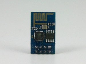
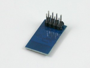
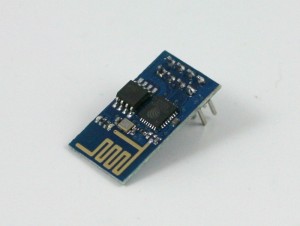
Continuing from my previous blog post about Hi-Link HLK-RM04 module, I have finally received the ESP8266 Serial-to-WiFi module that I’ve been waiting for. As I said previously, with the popularity of IoT devices, there is an increasing demand for low-cost and easy-to-use WiFi modules. ESP8266 is a new player in this field: it’s tiny (25mm x 15mm), with simple pin connections (standard 2×4 pin headers), and best of all, it’s extremely cheap, less than US$3 from Taobao.com!

IMG_3188IMG_3189IMG_3190

What is Serial-to-WiFi? Simply put, it means using serial TX/RX to send and receive Ethernet buffers, and similarly, using serial commands to query and change configurations of the WiFi module. This is quite convenient as it only requires two wires (TX/RX) to communicate between a microcontroller and WiFi, but more importantly, it offloads WiFi-related tasks to the module, allowing the microcontroller code to be very light-weighted.

There are already a lot of excitements and resources you can find online about ESP8266. I’ve included a few links below:

These are great resources to reference if you need help working with ESP8266. Below I document my own experience. I’ve also bought a few extra and put them available on the Rayshobby Shop for anyone who is interested in buying the module and don’t want to wait for the long shipping time from China 🙂


Check my new blog post on the ESP8266 Toy


Pin Connections. ESP8266 is sold in several different versions. The one I received is the version with 2×4 male pin headers, and PCB antenna. In terms of the form factor, it looks a lot like the nRF24L01 2.4G RF transceiver. Here is a diagram of the pins:
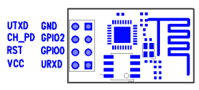
ESP8266_pinout
Connect the top two pins (UTXD, GND) and bottom two pins (VCC, URXD) to the RXD, GND, VCC, TXD pins of a microcontroller. Note that VCC must be no more than 3.6V. The middle four pins are should be pulled up to VCC for normal operation. However, if you need to upgrade the firmware of the module, you need to pull the GPIO0 pin to ground — that way upon booting ESP8266 will wait for a new firmware to be uploaded through serial. This is how you can upgrade the firmware in the future.

A few quick notes for connection:

  • The typical operating voltage is 3.3V (acceptable range is 1.7V to 3.6V). As the module can draw up to 200 to 300mA peak power, make sure the power supply can deliver at least 300mA. For example, the 3.3V line from a USB-serial cable would be barely sufficient, in that case it’s better to use a LDO to derive 3.3V from the 5V line.
  • When using the module with a 5V microcontroller, such as a standard Arduino, make sure to use a level shifter on the URXD pin — a simple resistor-zener level shifter is sufficient. Again, this is to prevent over-voltage.

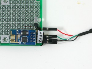
A schematic will make it clear. See below. In my case, I soldered the components and a matching female 2×4 pin header to a perf-board. This way I can easily plug in and unplug ESP8266. Again, if you are using a 3.3V microcontroller, you can do away with the LDO and zener diode.

esp8266_connIMG_3194

Experiments using a USB-Serial Cable. Before connecting to a microcontroller, it’s a good idea to use a USB-Serial cable (such as the inexpensive PL2303 USB-serial converter) to check out the basic functions of the module. Connect the PL2303 cable with ESP8266 according to the schematic above. Then open a serial monitor (such as gtkterms in Linux and putty in Windows) with 11520 baud rate (my ESP8266 seems to be set to 115200 bard rate; earlier versions use 57600). Then you can use a list of AT commands to talk to ESP8266. The AT commands are pretty well documented on this page. Below are some example input (shown in bold font) and output that show how to reset the module, list available WiFi networks, check the WiFi network it’s connected to, list IP address, and firmware version etc.


AT
OK
AT+RST
OK
ets Jan 8 2013,rst cause:4, boot mode:(3,6)
wdt reset
... ...
chksum 0x46
csum 0x46
ready
AT+CWLAP
+CWLAP:(0,"",0)
+CWLAP:(3,"freefly",-49)
OK
AT+CWJAP?
+CWJAP:"freefly"
OK
AT+CIFSR
192.168.1.130
AT+GMR
00150900
OK

A Simple Demo using Arduino.
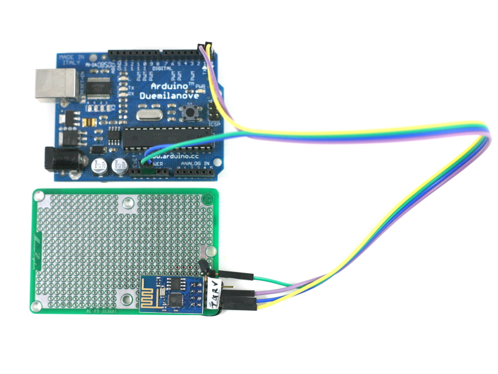
Next, I connected ESP8266 to an Arduino. Because Arduino is already using the TX/RX pins for bootloader, make sure to unplug ESP8266 while flashing the Arduino, otherwise you may not be able to upload a sketch successfully. Also, you can’t use TX/RX for printing debugging information, since ESP8266 will be using them to communicate with Arduino. Instead, you can use another pair of pins (e.g. D7 and D8) as software serial pins, and use a PL2303 serial cable to monitor the output. This will help print debugging information.

I’ve also experimented with using software serial to communicate with ESP8266, but that has failed — ESP8266 requires 115200 baud rate, and that’s a little beyond the capability of software serial. So you have to stick with the hardware TX/RX pins.

(Update: the code has been revised on Dec 14, 2014 to improve robustness, particularly for some of the latest ESP8266 firmwares. Right now there is still an issue that if the browser is closed before the transfer is completed, it may leave ESP8266 in the notorious ‘busy s’ mode, the only solution to which is to do a hard reset. If using the module in real products, make sure you have a way to use a microcontroller pin to reset the power of the module, thus providing a way to hard reset the module. It looks like future firmwares may be able to address this in software.)

The demo program first configures ESP8266 to log on to your WiFi network (SSID and password are given as macro defines at the beginning), then it sets ESP8266 as HTTP server with port number 8080, and it listens to incoming request. If you open a browser and type in http://x.x.x.x:8080 where x.x.x.x is the module’s IP address (printed to soft serial pins), you will see the output which is a list of analog pin values, and the page refreshes every 5 seconds. So this is a basic Hello World example that shows how ESP8266 can be configured as an IoT server, responding to incoming requests.

IMG_3193

Challenges. While my initial experiments with ESP8266 have been quite successful, I’ve also encountered minor issues that took me a while to figure out. For example, while the AT commands are well documented, they don’t seem extremely consistent — some commands allow question marks at the end, some don’t. I also see variations of the returned values from running the AT commands: sometimes there is an extra end of line character, sometimes there is none. These basically require a robust software library to handle all possible cases.

Overall I would say ESP8266 is a very promising WiFi module for IoT, particularly open-source IoT gadgets, because of its low cost, compact size, and the community development. It seems the manufacturer has also open source the firmware code, and thus the minor issues can probably be easily fixed through a firmware upgrade.

We have a small number of ESP8266 modules available in stock, and will continue to offer them if there are sufficient interests. Thanks!


Check my new blog post on the ESP8266 Toy

92 Responses to “First Impression on the ESP8266 Serial-to-WiFi Module”

  1. I’ve been having a play with these too, great little module and the price is amazing. The 0.922 firmware here allows you to change the baud rate (default now 9600) which allows use with software serial which is a big help: http://www.electrodragon.com/w/Wi07c#V0.922

  2. Eric says:

    Love the idea of the perfboard! If you don’t mind, which actual LDO, zener and resister combo did you go with?

    Thanks!

  3. Nerd Ralph says:

    A 220 ohm resistor instead of the zener would be an easier way to make a level shifter.

    • ray says:

      You are right, a series resistor would work just fine. When I first played with the module, I didn’t use any level shifter and even that worked fine (and luckily didn’t damage the module).

  4. Is it possible to assign a fixed IP?

    • ray says:

      I don’t remember if static IP is in the list of AT commands. Probably it’s best to set up a fixed IP on the router (using the DHCP reservation feature), by binding the IP to the WiFi module’s MAC address.

  5. Hans says:

    Thanks for all this!
    I changed your program in such a way that all printlines go to a 1.8″TFT display, so I do not use the softserial but print all to my TFT.
    I get the ip address of my esp8266 but then nothing happens…
    My problem is that the program stops in the void loop line:

    if(strncmp(buffer, “+IPD,”, 5)==0) {

    I print the string “buffer”, it has a length of 128 bytes and does contain the ip address and some unprintable chars, but obviously no +IPD…

    What am I doing wrong? Because of this the program does not start the webserver, so I cannot read the URL…
    Thanks for your help!

    • ray says:

      It’s possible that the preloaded firmware on your module is different from mine, so the output is somewhat different. If you print out the buffer and it doesn’t have +IPD, then just modify the code accordingly to remove the IPD checking.

  6. Hans says:

    BTW: if I repeat the Serial.readBytesUntil(‘\n’, buffer, BUFFER_SIZE); I always get the same string, even after 4 or 5 repeats…

  7. Hans says:

    I found the cause of my problem, in HardwareSerial.cpp I defined SERIAL_BUFFER_SIZE to 128 in stead of the standard 64…
    Now it works great! Thanks!!!

  8. mihai says:

    hi
    can we change the esp modeul ip address?
    many thanks

    • ray says:

      I am not sure. I didn’t see a command to set static IP. However, you can definitely bind a static IP by using your router’s DHCP reservation (or IP reservation) feature.

    • mihai says:

      thanks for your fast answer
      so the esp module works as dhcp client from standard?
      if i have a dhcp server with 192.168.1.x my esp module get 192.168.1.2 or the esp has a default address from factory(i wrote somewhere it has something like 192.168.4.1).
      it has a mac address default (and the mac not change over power off)?
      many thanks again

      • ray says:

        Yes, it works as dhcp client. The 192.168.4.1 IP you read about is its IP address when it functions as an AP. It has built-in hardware MAC address.

  9. Javier says:

    Hello,
    Great Article, I’ve been also playing with these modules.
    I’m trying to send a String to the module and excecute actions depending on string Received, but I’m having a little trouble comparing the results due to the serial interface getting chars instead of strings. I saw your example and it looks like the buffer way is the way to go, I have a question, if I use:
    if(strncmp(buffer, “+IPD,”, 5)==0) {
    this function can I modify the “+IPD”,5 to compare to whichever string I need it to compare to, am I right?? and the sscanf function is used for getting the IPD or the data? I’m a little confused on this.
    Thanks!!
    and again Great job!

  10. Lenny says:

    I don’t understand, the 3V3 from Arduino isn’t good?.

    • ray says:

      The 3.3V from Arduino is derived from the FTDI chip and my understanding is that it can’t supply more than 100mA of current. The WiFi chip requires 150mA to 250mA current, so it’s not sufficient.

  11. Thx for the great job … I tried to duplicate your setup and created a tiny webserver with this module and arduino… Actually my intention is to relay environmental data ( temp, humidity.etc) so I need to monitor digital inputs rather than only analogs… However my problem is that the unit stops transferring data at some point until I hard reset Arduino… I tried to monitor the point where the error is but softserial debug does not show anything… I added dbg.print() at all possible error points in the code but with no luck… at some point it stops sending data… any ideas?

  12. Thx for the fast response… Working consistently overnight is very good… 🙂 My connection never lasts for more than few mins… sometimes stops after 10-15 refreshes… 🙁

    • Alan Mera says:

      Im having the same problem with the unit stopping after about 5 refreshes. Anyone resolve this issue?

      • ray says:

        This may be because your ESP8266 comes with a newer firmware. Here is what I suggest:
        1. Change all Serial.println(xxx); to Serial.print(xxx); followed by Serial.print(“\r\n”). This makes sure the mcu always sends \r\n as the end of line.
        2. In the loop() function, at the end of the if(strncmp(buffer, “+IPD,”, 5)==0) { } statement, add buffer[0]=0; to clear out the buffer

      • Thx again for the help… I tried your suggestions and modified all “println” commands… Added buffer clear statement into loop routine with no luck…
        Only thing changed is this time it stops sending data after first refresh… 🙁

      • ray says:

        The code has been updated. Please download the new file and try again.

      • ray says:

        The code has been updated. Please download the new file and try again.

      • Ray,
        Many thx for your continuing support for this little ESP8266 unit… I downloaded your new demo sketch immediately and tested… The unit connects to my wifi network as before but this time I cannot reach it with my browser (with its IP) and no data is received… my browser tries to get data for 30secs and then timeouts… I am attaching my dbg window log for you to inspect… regards…
        dbg serial window log:
        begin.
        AT

        OK
        AT+CWMODE=1

        no change
        AT+RST

        OK
        AT+CWJAP=”Dincer”,”dincer5616″

        busy now …

        ets Jan 8 2013,rst cause:4, boot mode:(3,7)

        wdt reset
        load 0x40100000, len 24444, room 16
        tail 12
        chksum 0xe0
        ho 0 tail 12 room 4
        load 0x3ffe8000, len 3168, room 12
        tail 4
        chksum 0x93
        load 0x3ffe8c60, len 4956, room 4
        tail 8
        chksum 0xbd
        csum 0xbd

        ready
        AT+CIPSTO=30

        ERROR
        AT+CIPMUX=1

        OK
        AT+CIPSERVER=1,8080

        OK
        device ip addr:AT+CIFSR

        192.168.1.102
        Link

        +IGET.1
        Ho68.0
        C: k
        Act/hcat+xmlion9,imag*;qr-Ailladow WOWWeb6 (Ke Geme/310137.3-Ench
        Accept-LangTR,ten-Un;q
        OK
        Link
        Link

        +IGET.1
        Ho68.0
        C: k
        Act/hcati+xmlion9,imag*;qr-Agilladow WOWWeb6 (Ke Gece/310137.3-ch
        Accept-LangTR,tn-Un;q=OK
        Unlink
        Link

        +IGET.1
        Ho68.0
        C: k
        Carol:0
        ext/ical+xml,on/,im*/*;er-zillndo; WOeWeb6 (Ke Gome/.1-Encip,dcUnlink

  13. Marcel says:

    I’m rather excited to have just got my module working! Hoorah!
    In trying your example code I’m getting an error code: 2 (when I’m not getting an error:1)

    Any suggestions?

    • ray says:

      That’s probably because your module is already in mode 1. Please try the updated file in the post and see if it solves the problem.

  14. GTA18 says:

    Hi,

    I just bought an esp8266-02 from amazon and had it communicating at 9600 baud but it just echoes back whatever I send it.

    When I reboot it using the reset pin (momentary connect to gnd) it gives me a welcome message

    ATATATATŽþ$‡š
    [Vendor:www.ai-thinker.com Version:0.9.2.4]

    ready

    After this, it just echoes whatever I type in.
    AT
    AT
    Has anyone have any experience with this chip?

    thanks!

    • Anonymous says:

      I have the same result with 0.9.2.4 firmware at 9600 baud. Please post if you have any ideas.

      • ray says:

        I don’t have 0.9.2.4 firmware and I can’t test. The code is provided as is. One possibility is that the new firmware has changed the end of line character. You can use a serial monitor which supports different end of line configurations. For example, Arduino’s serial monitor provide this option.

      • gta18 says:

        I actually flashed it with the v0.91 from https://onedrive.live.com/?cid=C4DDF72E6EEA3826&id=C4DDF72E6EEA3826%21872

        and I got it running at 56k. I can now connect it to wifi and was able to test the UDP and TCP CIP messaging function.

        Maybe there is a bug on the v0.92.

        I’ll stick with the older version for now till I get more time to dive into it.

        Still tied up tinkering with my MM2 3d printer and flying Multirotors… too many hobbies…

      • ray says:

        Updated code is available in the post.

      • Anonymous says:

        I used PUTTY with serial setup. PUTTY seems to have issues with ESP8266. Changing to coolterm works.

    • ray says:

      I’ve cleaned up the code to make it more robust. You can try the updated file in the post. It should be able to work with the latest firmware.

      • Walter says:

        Dear Ray,
        thanks for your update and precious support.
        I’ve downloaded new code, but I’m still having problem with firmware 0.9.2.4 .
        Following is the log on dbg serial:

        begin.
        AT?AT???AT?AT?$??4a?RAT?OAT???AT?E?j?device ip addr:AT?)?

        I’ve also tried to test esp module connecting it to serial port and sending to it AT commands. In this case esp just echoes whatever I type in, as reported by GTA18.
        In my understanding it can be due to an erroneous serial configuration or a esp8266 firmware bug.
        My environment is set as follow:
        -esp firmware version 0.9.2.4;
        -esp serial set at 9600;
        -debug serial set at 9600, I’m using gtkterm set on 9600-8-N-1 as serial monitor;
        NOTE:I haven’t a PL2303 USB-serial converter, so I’m connecting esp module to PC with a serial cable and a max232 ic to shift voltage signal to esp compatible values.

        Could problems be due to my environment setup?
        What do you suggest: downgrade the firmware to earlier version or what else?

        Thanks a lot for your support and kindness.
        Best Regards,
        Walter

  15. nonokunono says:

    Official firmware at AT command 020
    new firmware brings AT commands for hardware sleep mode,
    (AT+CIPSTAMAC , AT+CIPAPMAC )
    MAC address change for station and ap mode.

    http://www.filedropper.com/at020 (just write it to address 0 )
    http://wikisend.com/download/669568/at020.bin

    screenshot here:
    http://postimg.org/image/ywh96pk3f/cc856977/

  16. Walter says:

    Hi Ray,
    thanks for your article.
    I’m engaged with some issues while I try to get your sketch .ino file.
    Could you please re-post it or could you please suggest another way in order that I can be able to download it?
    Thanks in advance and Best Regards.

  17. mike says:

    Hi Ray,

    I’m trying to submit to a server page with this GET command:-

    cmd = “GET /recorder.php?DATA=1&D1=2.555&D2=7.8&D3=5\r\n”;

    Do I need to use HTTP host header or IP address of hosted website.
    Sorry if this is not the place to ask, but just saw your site and thought you could help.
    Kind Regards
    Mike

  18. Giuliano says:

    Thanks fot your article. I’m thinking about how to use the GPIO. Any experience about ? I need to test the GPIO level and if it’s High just send a broadcast on my LAN. If it’s possible I can use the ESP module in a stand alone configuration instead of ESP+Arduino.

  19. anurag goyal says:

    i am running esp from hyperterminal. all configuration has been done.

    AT+CIPMUX=1
    AT+CIPSERVER=1,80

    from browser i send request with ip 192.168.1.3

    i got request on hyperterminal with ipd 0

    then i enter command

    AT+CIPSEND=0,120

    after that got “>” prompt.

    then i enter string as it is on hyperterminal:

    HTTP/1.1 200 OK\r\nContent-Type: text/html\r\nConnection: close\r\nRefresh: 5\r\nContent-Length:15\r\n\r\nANURAGGOYAL1234

    after that i got response SEND OK

    but no data is received at browser. please tell where i am doing mistake.

  20. […] the diode zener is necessary when I want to connect the module to a PIC but what about PC? http://rayshobby.net/?p=9734 Thanks a lot Reply With […]

  21. Ben says:

    I already followed your rmo4 project and got it running. Now i´m trying to get the esp8266 but can´t even compile ur sketch… which IDE did u use ?
    best regards and merry xmas

  22. […] for the ESP8266 AT firmware using an arduino. Most credits go to this guy, where i got the basics : http://rayshobby.net/?p=9734 […]

  23. Robotic Boyer says:

    I and my friend Carlo have made a version using Arduino Uno and ESP on SoftwareSerial starting from Ray’s version.

    The Gist link:
    https://gist.github.com/roboticboyer/81cea1b44894e1cb4352

  24. […] Questo codice è frutto dell’elaborazione dell’esempio di http://rayshobby.net/?p=9734 […]

  25. […] Great first impression write up with helpful links and Pin out information http://rayshobby.net/?p=9734 […]

  26. MarKoZaKKa says:

    Hi all, I would like to know if it’s possible to setup an MCU to MCU link with the ESP8266, one-to-one and/or one-to-many, without having a smarter device (e.g. a PC or a Raspberry) in the middle to manage data traffic.
    Thank You!

    • ray says:

      You can use Serial, or I2C to let two MCUs talk to each other.

      • MarKoZaKKa says:

        …sorry, I mean a _wireless_ link… Is it possible to use the ESP8266 this way? My first need is to connect a remotely placed MCU to another one, the second need is to have a net of slaves MCU answering to the addressed calls placed by a master MCU.
        thank you.

      • ray says:

        Yes, it should be possible. There are two options: 1) if you have a separate WiFi router, you can have both set in STATION mode and connect to the WiFi router; 2) if you don’t want to involve a separate WiFi router, you can set one ESP8266 in AP mode, the other in STATION mode, and have the second one log on to the first one’s network.

      • MarKoZaKKa says:

        Ok, that’s what i need to know. And, this way, i can set the module connected to the master MCU as a AP, and the n others modules connected to the slaves MCU as STATION, getting a point-to-multipoint communication, right?

  27. Ki Myung JI says:

    I want
    I want to learn about the esp8266.
    After purchasing the module and the module program I want to learn how to drive a smart phone.
    I want to learn about small GPIO.
    Where are you can learn from?

  28. Ktysai says:

    @ray @MarKoZaKKa:
    Have you tried to use the module in AP mode and to connect another one to it?
    I am curious what is the maximum distance that can be between the devices in this mode.

    Using SERIAL link through Bluetooth modules I can go around 5-6 meters without obstacles.

    @ray: thanks for sharing!

  29. surajit says:

    Hallo,
    I am working on a project with the ESP8266 and need to define requirements so I have different options. I want to use the
    ESP8266 connected to Atmel8051 microcontroller to collect sensors data and communicate with a mobile app that sends these data to
    the cloud. So I am trying to figure out how to set the ESP8266 to talk to the mobile app. The mobile app would be like a
    bridge between the ESP/8051 system and the cloud. The mobile phone can be set as tethering or portable hotspot via Wifi
    and connect to the cloud via 3G. Would like to have some suggestions for the best setup for the ESP8266/atmel8051 in this
    configuration?

    • alex says:

      Hello,
      I’m using this module for some projet.
      For what you need I propose You to flash a custom firmware with lua suport. You can write a small script inside ,and also possibility to setup static ip.
      Hope this sill help You
      Alex

  30. Ashwini says:

    hello,
    I have send my data to thingspeak. can i go for sending data from one esp8266 to another one.?
    If yes then how it would be??
    Please leave reply.

  31. Jinu says:

    Thanks for sharing this . I am testing my esp8266 to configure as webserver with different sketches for last one month, and this one fix my issue , really good and much stable than other sketches .

    Is it possible to add a timer to monitor the ESP hanging and initiate a hardware reboot pulse to the Arduino and ESP8266.

    • Jinu says:

      I am finding the ESP is getting rebooted after 20 min and the web server is not getting restarted after that .

      > HTTP/1.1 200 OK
      Content-Type: text/html
      Connection: close
      Refresh: 5
      Content-Length:65

      AM1:0,AM2:0,SW1:0,SW2:0,FP1:0,FP2:0,FW1:0,FW2:0,TW1:0,TW2:0,CM1:0
      SEND OK
      0,CLOSED
      1,CONNECT FAIL
      .
      .
      .
      ..

      1,CONNECT FAIL
      1,CONNECT FAIL
      1,CONNECT F@fÌÈJþZGbc dRFD{“?LÎB‡Â
      πÄì£C¡¥µThinker Technology Co. Ltd.

      ready

      Stuck in this point 🙁

    • ray says:

      I believe ESP8266 has a watchdog timer to do what you needed.

  32. tHIAGO says:

    Hello Mr Ray!

    I follow all instructions in tutorial and videos, you did a great Job, congratulation.

    But i am having problem with last part of tutorial. I configurate my ESP8266 to connect to my acess point it is ok and run well, i receive the follow IP 192.168.0.170

    I have a biggest doubt about the connection with arduino. I tried using connection using a supply external to 3.3 Volts and conect arduino GND to GND of supply. And connected TX of ESP8266 to RX to Arduino and vice-versa. And tried connect directly with Arduino too.

    I see than you build a PCB board to make the connections is not clearly to me see.
    I tried the follow URL in Browser
    192.168.0.170
    192.168.0.170:8080
    http\\192.168.0.170:8080
    No Sucess, my web page give a error and not load nothing.

    My connect is

    VCC (ESP8266) = 3.3Volts (Supply)
    GND (ESP8266) = GND(Supply)
    TX (ESP8266) = RX(Arduino)
    RX(ESP8266) = TX(Arduino)
    GND(Arduino) = RX(Supply)

    Please what i am doing wrong?!
    Thank you for the support!

  33. Thiago says:

    I see about zener-resistor here Mr Ray

    and fixing the type was http:\\192.168.0.170:8080
    thank you

  34. Muzammal Baig says:

    Dear Thiago,

    the TXD signals of arduino would be +5V so your module can listen to what arduino says but
    arduino wouls expect a +5V =1 signal on the RXD line which ESP does not have

    so either use an open collector buffer both ways to remove voltage incompatibility or use an arduino working at 3.3V like the MEGA

  35. Sandesh K A says:

    Hi Ray , it is a beautiful article . I am working on EP8266 . I am logging gps co-ordinates from arduino to webserver running on my laptop . Python script is executed in the webserver which get the co-ordinates and returns the full address . I want to make HTTP POST to the webserver through ESP8266 , but i am not getting the correct code after hours of surfing the internet. You are the right person to answer this . Please can you make it ?

  36. Peter says:

    Hello

    I’m quite new to arduino and esp8266. Currently I’m trying a simple thing – connect arduino UNO to wifi network using ESP8266 and read a webpage from the internet.

    I’m using the AT firmware on ESP8266. I can connect it to wifi and open a TCP connection to web server, pass the URL I want to receive, but I have the following problem:

    while (Serial.available()){
    char c = Serial.read();
    dbgSerial.write(c);
    strReceived+=c;
    }

    This gives me exactly what I need to my debug console – the whole HTTP response together with the content. The moment I comment out the debug output to soft serial, I only get very little data from the server. When I add a delayMicroseconds(50) after Serial.read(), I get a little more data to strReceived, but never as much as when I use the serial debug.

    any advice?

    AT+GMR output:
    AT version:0.21.0.0
    SDK version:0.9.5

    thank you very much

  37. Raaj says:

    Hello,
    I’m tying to transmit the ADC value of PIC 16F877a to ESP8266
    function to calculate the ADC value :
    {ADCON0bits.GO = 1;
    while (ADCON0bits.GO == 1);
    a=ADRESH&0x03;
    a=a<<8|ADRESL; }
    now I need to transmit the value 'a' through wifi. So what AT command should be used to transmit this value from PIC controller to WIFI
    if I use UART_Write_Text("a");
    only the character 'a' is being transmitted rather than the value stored in 'a'.
    kindly help me

  38. Petre says:

    Hi

    Thank you for the info – very helpful.

    A few of questions if I may?
    1. Some sites say that only the GPIO0 pin should get 3.3v. I’ve tried both your instructions of connecting all the “left over” pins to 3,3v, and then just GPIO0 – but I still cannot seem to get my board to connect to my AP.
    2. Can I run the TX and RX pins through the LDO as well – I have one that can level 6 separate feeds?
    3. You Arduino code sketch – which Arduino board did you use? When you refer to using Software Serial for debugging, and specifically, using pins 7 and 8 for those purposes – how does that work / refer to an Arduino Nano x3? IE, should I connect wires to pin 7 and 8 – and then to GPIO0 and GPIO1 on the ESP? I tried running the code “as-is” with my SSID and password, but I get no activity on my AP, and obviously, no return responses from the AT commands when monitoring the serial port in Arduino UI, so I am not sure if the ESP is even receiving the AT commands?

    Thank you for your responses in advance.

    • ray says:

      1. I agree that only GPIO0 needs to be pulled high. If you can’t get the board to connect to your AP, there is slight possibility your ESP8266 module is defective. Consider changing it and try again.
      2. Only URXD pin (i.e. the RX pin on ESP8266) needs to have a level shifter. You can certainly use LDO to achieve level shifting.
      3. I used Arduino Duemilanove, but other versions like Arduino Uno, Pro, Nano would work just the same. Software serial means you pick two pins on Arduino (say 7 and 8) and use them as TX/RX, and connect them to RX/TX of ESP8266. The RX/TX pins of ESP8266 are different from GPIO0 and GPIO2 — they are different sets of pins.

      • Petre says:

        Hi Ray

        Thanks -I actually got it working now. However, I’m still not clear on how the software serail should work.

        My problem is that I need to be able to see the responses from the WiFi module somehow – I need to get the MAC address of the module since my WiFi network is access controlled.

        Whether I use the software serial debug on pins 7 & 8, or connect to the TX and RX pins on my Uno, I only ever see the commands that is sent to the wifi module, but never the responses – not even the expected OK after the AT…

        Please point me in the right direction?

    • Petre says:

      Hi Ray

      Looks like my response to your reply got deleted or lost.

      At first I thought I made a breakthrough, since it looked like I could get my ESP to connect to my iPhone hotspot – the hotspot connected indicater came on on my iPhone. However, I could then not verify what the ip was for the ESP, so I tried to just change AP details to my other WIFI AP. Now I cannot see any activity on that AP when trying to connect.

      I also try to set ther MAC address of the wifi module, since I’m not seeing it with apps like Fing on my iPhone – and it looks like the hotspot simple gives the ESP the same IP.

      I also tried another ESP, but the same result, so something with my wiring/script could be wrong?

      I modified your script. I am now running tx/rx on UNO directly to ESP:

      /* ====== ESP8266 Demo ======
      * Print out analog values
      * (Updated Dec 14, 2014)
      * ==========================
      *
      * Change SSID and PASS to match your WiFi settings.
      * The IP address is displayed to soft serial upon successful connection.
      *
      * Ray Wang @ Rayshobby LLC
      * http://rayshobby.net/?p=9734
      */

      // comment this part out if not using LCD debug

      #define BUFFER_SIZE 512

      #define SSID “Arduino” // change this to match your WiFi SSID
      #define PASS “password” // change this to match your WiFi password
      //#define SSID “iPhone” // change this to match your WiFi SSID
      //#define PASS “password” // change this to match your WiFi password

      #define PORT “8080” // using port 8080 by default

      char buffer[BUFFER_SIZE];

      // If using Software Serial for debug
      // Use the definitions below
      #include
      SoftwareSerial dbg(7,8); // use pins 7, 8 for software serial
      #define esp Serial

      // If your MCU has dual USARTs (e.g. ATmega644)
      // Use the definitions below
      #define dbg Serial // use Serial for debug
      //#define esp Serial1 // use Serial1 to talk to esp8266

      // By default we are looking for OK\r\n
      char OKrn[] = “OK\r\n”;
      byte wait_for_esp_response(int timeout, char* term=OKrn) {
      unsigned long t=millis();
      bool found=false;
      int i=0;
      int len=strlen(term);
      // wait for at most timeout milliseconds
      // or if OK\r\n is found
      while(millis()=len) {
      if(strncmp(buffer+i-len, term, len)==0) {
      found=true;
      break;
      }
      }
      }
      }
      buffer[i]=0;
      dbg.print(buffer);
      return found;
      }

      void setup() {

      // assume esp8266 operates at 115200 baud rate
      // change if necessary to match your modules’ baud rate
      esp.begin(115200);

      dbg.begin(9600);
      dbg.println(“begin.”);

      setupWiFi();

      // print device IP address
      dbg.print(“device ip addr:”);
      esp.println(“AT+CIFSR”);
      wait_for_esp_response(1000);
      }

      bool read_till_eol() {
      static int i=0;
      if(esp.available()) {
      buffer[i++]=esp.read();
      if(i==BUFFER_SIZE) i=0;
      if(i>1 && buffer[i-2]==13 && buffer[i-1]==10) {
      buffer[i]=0;
      i=0;
      dbg.print(buffer);
      return true;
      }
      }
      return false;
      }

      void loop() {
      int ch_id, packet_len;
      char *pb;
      if(read_till_eol()) {
      if(strncmp(buffer, “+IPD,”, 5)==0) {
      // request: +IPD,ch,len:data
      sscanf(buffer+5, “%d,%d”, &ch_id, &packet_len);
      if (packet_len > 0) {
      // read serial until packet_len character received
      // start from :
      pb = buffer+5;
      while(*pb!=’:’) pb++;
      pb++;
      if (strncmp(pb, “GET /”, 5) == 0) {
      wait_for_esp_response(1000);
      dbg.println(“-> serve homepage”);
      serve_homepage(ch_id);
      }
      }
      }
      }
      }

      void serve_homepage(int ch_id) {
      String header = “HTTP/1.1 200 OK\r\nContent-Type: text/html\r\nConnection: close\r\nRefresh: 5\r\n”;

      String content=””;
      // output the value of each analog input pin
      for (int analogChannel = 0; analogChannel < 6; analogChannel++) {
      int sensorReading = analogRead(analogChannel);
      content += "analog input ";
      content += analogChannel;
      content += " is ";
      content += sensorReading;
      content += "\n”;
      }

      header += “Content-Length:”;
      header += (int)(content.length());
      header += “\r\n\r\n”;
      esp.print(“AT+CIPSEND=”);
      esp.print(ch_id);
      esp.print(“,”);
      esp.println(header.length()+content.length());
      if(wait_for_esp_response(2000, “> “)) {
      esp.print(header);
      esp.print(content);
      } else {
      esp.print(“AT+CIPCLOSE=”);
      esp.println(ch_id);
      }
      }

      void setupWiFi() {
      // try empty AT command
      esp.println(“AT”);
      wait_for_esp_response(1000);

      // set mode 1 (client)
      esp.println(“AT+CWMODE=1”);
      wait_for_esp_response(1000);

      // reset WiFi module
      esp.print(“AT+RST\r\n”);
      wait_for_esp_response(1500);
      delay(3000);

      //set MAC
      esp.print(“AT+CIPAPMAC=\”2c:aa:35:97:d4:7b\”\r\n”);
      wait_for_esp_response(1500);
      delay(3000);

      //set MAC2
      esp.print(“AT+CIPSTAMAC=\”18:aa:35:97:d4:7b\”\r\n”);
      wait_for_esp_response(1500);
      delay(3000);

      // join AP
      esp.print(“AT+CWJAP=\””);
      esp.print(SSID);
      esp.print(“\”,\””);
      esp.print(PASS);
      esp.println(“\””);
      // this may take a while, so wait for 5 seconds
      wait_for_esp_response(5000);

      esp.println(“AT+CIPSTO=30”);
      wait_for_esp_response(1000);

      // start server
      esp.println(“AT+CIPMUX=1”);
      wait_for_esp_response(1000);

      esp.print(“AT+CIPSERVER=1,”); // turn on TCP service
      esp.println(PORT);
      wait_for_esp_response(1000);

      }

  39. k chandrshekar says:

    hello ,
    I am working on notice board by using arduino and esp 8266.
    I have some problem , i can’t able to solve .
    Problem is , I can’t able receive above 64 characters data. any size limit is their for data sending?
    can you give any suggestions
    thank you.

  40. his gives me exactly what I need to my debug console – the whole HTTP response together with the content. The moment I comment out the debug output to soft serial, I only get very little data from the server. When I add a delayMicroseconds(50) after Serial.read(), I get a little more data to strReceived, but never as much as when I use the serial debug.

  41. Marcelo DeOliveira says:

    Hi
    I am trying to make a device that you find with your smartphone but the SSID AND PASSWORD, is put after a initialization. In other words, you connected the phone to the ESL and it shows inbthe wifi list, after that ypu connect to it and hard write your SSID AND PASSWORD. After that you connect to the home wifi again and now the esp is in your network and all you need to do is to type its ip.
    This is how most of the IOT are done.
    Thanka

  42. jjaijg says:

    hiiii…..
    am using arduino MEGA..how to use serial port for communicating with esp8266…plzz hlp me

  43. Anonymous says:

    HI buddy
    i tried below code and connected esp to pins 2 and 3 but i was not getting response from esp.
    i tried all the baud rates for esp but didnt work.please help me
    #include

    SoftwareSerial esp8266(2,3); // make RX Arduino line is pin 2, make TX Arduino line is pin 3.
    // This means that you need to connect the TX line from the esp to the Arduino’s pin 2
    // and the RX line from the esp to the Arduino’s pin 3
    void setup()
    {
    Serial.begin(9600);
    esp8266.begin(115200); // your esp’s baud rate might be different
    }

    void loop()
    {
    if(esp8266.available()) // check if the esp is sending a message
    {
    while(esp8266.available())
    {
    // The esp has data so display its output to the serial window
    char c = esp8266.read(); // read the next character.
    Serial.write(c);
    }
    }

    if(Serial.available())
    {
    // the following delay is required because otherwise the arduino will read the first letter of the command but not the rest
    // In other words without the delay if you use AT+RST, for example, the Arduino will read the letter A send it, then read the rest and send it
    // but we want to send everything at the same time.
    delay(1000);

    String command=””;

    while(Serial.available()) // read the command character by character
    {
    // read one character
    command+=(char)Serial.read();
    }
    esp8266.println(command); // send the read character to the esp8266
    }
    }

  44. David says:

    Trying to compile your code above I get:

    ‘esp’ was not declared in this scope

    I have made no modifications to the code except my SSID and password.
    (PS – Module is accepting AT commands via serial)

    Please advise?

  45. Neelima says:

    hello
    I want to use esp8266 with STM8S103F3 as serial to wifi module.I connected esp to PC with FTDI chip .AT commnads work fine.Now i want to interface esp8266 with my ST microcontroller.I have connected RX TX tof esp to TX and RX of micro and GND common.
    Now I send some characters from my Iphone app(special app designed for sending chars to wifi module) but i dont see those chars are recived by esp8266.I verified it by watching UART registers of ST micro(in debug mode)
    Does esp8266 has webpage where i can monitor RX and TX bytes? like other wifi modules?e.g HLK .they have web page where we can see this data

  46. sri says:

    can u tell me the exact distance of esp8266 wifi module

  47. noman yousaf says:

    hi,
    thanks for your great efforts.
    i have a question.
    can i use 2 wifi modules as remote control system like i have done with 2, hc-05 bluetooth modules,without internet connection?
    thanks in advance for your reply.

    regards.

  48. Bob J says:

    I got you example working.
    Thank you very much for the simple straight forward easy to understand sketch, it got me going when I was stuck working with other sketches.
    One change I made was to add a 1000mS delay between each AT commands. Before I added this delay I got the dreaded “busy” very often. Now it is solid and no “busy” errors at all.
    I believe the “OK” may be in some cases be returned by the esp8266 before the present command is fully processed. This type of modem coding error I saw many years ago in dial-up modem firmware (dating myself a bit here).
    I also added a control line from the micro to the power down pin of the ESP8266 to do a hard reset at the very start of the sketch.
    I has now run over 2 days straight without a glitch.
    Thanks again for the great post

  49. Praveen Sagar says:

    Hello, I’ll connected to the wifi8266 with arduino uno btb in the serial monitor that result will getting wrong output that is timeout so tuat how can I solve that problem?

Leave a Reply