This is the first article in a series that I call ‘Learning Electronics’. The goal is to learn and experiment with basic electronic circuits. The first circuit I will discuss here is the astable multivibrator. This is a very simple oscillator circuit that can be used to generate square waves. Here is the schematic of a standard astable multivibrator:
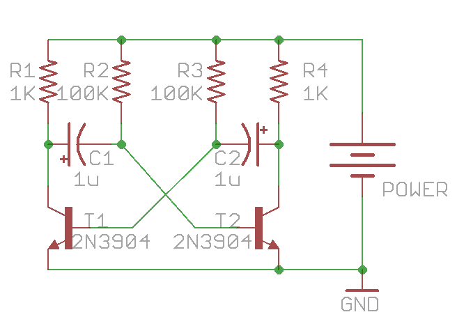
It consists of only two NPN transistors (T1 and T2), two capacitors (C1 and C2), and four resistors (R1-R4), organized in a symmetric fashion. The collectors of T1 and T2 are outputs, which provide complement square wave signals. The values of the capacitors and resistors can vary depend on the desired frequency, and their values do not have to be symmetric.
Update: as some readers pointed out, for square wave output, the resistor values should satisfy: R2 / R1 < h_fe, where h_fe is the transistor's current gain (same for R3 and R4). As h_fe is usually around 80 to 250 for 2N3904, the specific values above (R1=1K, R2=100K) are close to the margin. To improve this, consider increasing R1 or decreasing R2. Alternatively, you can replace 2N3904 with BC547, or even a Darlington transistor (e.g. MPSA14), which have higher h_fe values.
Principles
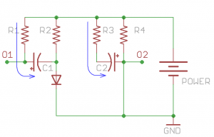
So how does the circuit work? To begin, when power is applied, theoretically both T1 and T2 should turn on, since their base pins are connected through resistors (R2 and R3) to Vcc. However, due to small differences in the electric properties, one of the them will turn on slightly earlier than the other. Without loss of generality, let’s assume T2 turns on first. Therefore, T2’s collector begins to conduct and can be thought of as ‘shorted’ to ground. Note that C2’s right lead is connected to T2’s collector, and since C2 is not charged yet, its left lead also has a voltage close to ground. This immediately shuts off T1, i.e. T1 becomes an open circuit. Therefore C1’s left lead is in floating status, and its right lead is connected to T2’s base, which is about 0.7V due to the forward voltage drop of transistors. This forward voltage drop is the same as a diode. So at this moment, the circuit is equivalent to the following:
During this period, T2’s collector (output O2) remains low, and C2 begins to charge through R3. Thus the voltage on C2’s left lead will rise, and the rising time depends on R3 x C2. At the same time, C1 also charges, through R1, which is typically a small resistor (e.g. 100-1000 ohm). So C1’s left lead (output O1) will quickly rise up to Vcc and remains high.
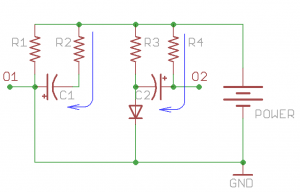
As C2 continues to charge, a critical moment will happen when its left lead rise up to 0.7V, at which moment transistor T1 will turn on, and its collector will conduct to ground. Note that since C1’s left lead is connected to T1’s collector, it will also drop to ground voltage. As C1 is fully charged, it’s right lead will suddenly drop to a negative voltage (-Vcc). This will shuts off T2 firmly. Therefore the circuit will suddenly transition to the following equivalent:
During this period, output O1 will remain low, and output O2 will quickly rise to Vcc (due to the charging of C2 through a small resistor R4). At the same time, C1 charges through R2 and the voltage on its right lead will rise over time determined by R2 x C1. Now you can predict what’s going to happen: as C1 continues to charge, the next critical moment happens when C1’s right lead rises above 0.7V. At that point, T2 will conduct again while T1 shuts off. The same cycle will repeat. There you go, oscillators!
Analysis
Now we have to do some calculus to find out the frequency of the oscillator. Let me focus on output O2. As it alternates between low and high, it approximates a square wave. How to find out the frequency? Note at the end of stage 1, C1 has a voltage of (Vcc – Vb) across it (where Vb = 0.7V). Again, the voltage establishes very quickly because R1 is small. The moment the circuit transitions from stage 1 to stage 2, C1’s right lead has an initial negative voltage: -(Vcc – Vb), and the circuit remains in this stage until that lead rises up to +Vb. So let’s calculate how long this will take. There are ready-made equations to compute this, but here let me derive it from basic differential equations.
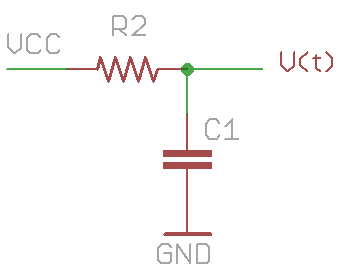 To start, the problem can be simply stated as follows: a resistor R2 and capacitor C1 are connected in series between Vcc and ground. C1 has an initial voltage of -(Vcc – Vb). How long does it take for C1’s voltage to rise up to +Vb? Let’s assume C1’s voltage is V(t): a function that changes over time. According to the law of capacitor, the change of V(t) is equal to the current flowing through it divided by the capacitance:
How much is the current i(t)? That’s equal to the current flowing through the resistor R2, thus
putting them together:
This is a simple differential equation. We can rearrange it to the following form:
By using the fact that
and integrate both sides, we get:
where K is a constant. Using the knowledge that when t=0, V(t)= -(Vcc – Vb), we find out
so:
Recall that our goal is to find hen V(t) is equal to Vb, so substitute Vb to V(t), and solve for t:
Under the assumption that Vcc is much larger than Vb, this is approximately equal to:
This is how long stage 2 will last. Similarly, stage 1 will last for approximately
Therefore, a full cycle will take
before the next cycle begins. The frequency of the wave is thus:
Viola! We are done!
With the given values in the first schematic (C1=C2=1uF, R2=R3=100K), the frequency is roughly 6.5Hz. These symmetric values can produce a square wave of 50% duty cycle. But they do not have to be symmetric. By using different R2 and R3 (or different C1 and C2), you can easily create waves with any desired duty cycle.
Practice
It’s very easy to prototype the circuit on a breadboard. Here is an example:
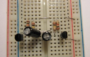
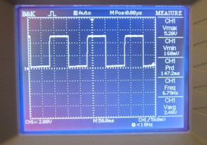
Connecting an oscilloscope to output O2, the result shows a decent square wave with 50% duty cycle at about 6.7Hz. Looks quite nice.
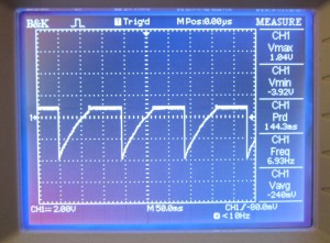 I also checked the signal on T2’s base pin. The result is on the left. As you can see, the beginning of stage 2 is signaled by the jump to a large negative value. During this stage, C1 charges through R2, so T2’s base voltage rises continuously. As soon as it crosses Vb, T2 conducts, and its base remains at Vb until the start of the next cycle.
Next, let’s blink some LEDs with the oscillator. You can either connect LEDs in series with R1 and R4, or directly to output O1 and O2. Check the video below (the circuit below uses C1=C2=10uF):
Finally, if you want, you can make a printed circuit board, so you can carry it around, or use it to decorate a toy with flashing LEDs. Enjoy!
Appendix
Frequency change when connecting LEDs with R1 and R4 in series
As mentioned above, one way to connect LEDs into the multivibrator is by putting them in series with R1 and R4. One interesting thing I noticed is that when doing so the frequency of the LED blinking is much faster than the calculated frequency. So what’s happening? A careful analysis reveals that this is not surprising. The main reason is that because the LED will drop about Vled=2V, C1 and C2 will not be charged all the way to Vcc-Vb anymore. Instead, they are charged to about Vcc-Vb-Vled. Consequently, it takes less time for C1 or C2 to charge from a negative voltage to +Vb, hence the oscillation frequency is faster. The precise formula is actually:
Since Vb+Vled is quite significant compared to Vcc, we cannot make the same approximation as above anymore. For example, with the given values in the first schematic (C1=C2=1uF, R2=R3=100K), and assume Vcc=+5V, the frequency is now roughly 10Hz (compared to 6.5Hz when LEDs are not connected). So this explained why the LED blinking speed seems faster than calculated.
 Stage 1
 Stage 2
[…] transgression, but it stems from our discomfort with analog circuits. Luckily, [Ray] published an illustrated guide on building multivibrator circuits. This is a simple method of assembling a two-output oscillator. All it takes is a pair of NPN […]
Great post! I’m looking forward to seeing more like this.
Note that if Vpower is reaches or exceeds approx. 9 V an additional diode in each emitter connection of the NPNs is required to avoid reverse breakdown of the B-E junction which occurs at around that voltage. The reverse breakdown will discharge the capacitors much faaster than calculated thus raising the frequency of the oscillator.
Regards,
Harald
True. It’s often easy to forget the B-E reverse breakdown voltage. Thanks for reminding.
[…] transgression, but it stems from our discomfort with analog circuits. Luckily, [Ray] published an illustrated guide on building multivibrator circuits. This is a simple method of assembling a two-output oscillator. All it takes is a pair of NPN […]
In your circuit you show polarized capacitors and have them charging to a negative voltage (albiet only 0.7v and for quite a short time). Would this not shorten the life of the capacitors or does it really make no difference at this voltage? My understanding is that you should use unpolarized in an application like this.
This is an excellent article. I am looking forward to seeing the rest.
I dont think it makes any difference in terms of the capacitor life. In any case, this is a fairly standard circuit, I am sure someone has tested it for reliability.
This is a great find. Good Work.
Hi. There is a problem with your circuit: base current is barely enough to saturate the transistors. With your current setup, Rb/Rc=100, so transistor must have a current gain of at least 100. This is not always true, even for small signal transistors like 2N3904. With high power transistors (less current gain) the circuit will certainly fail to oscillate.
You are right, that is a concern. Replacing 2N3904 with a darlington transistor (such as MPSA14) will solve this problem.
Pardon my ignorance – the mathematically ‘never saw the point’ crowd – but in the appendix portion of the article do I see a clue to why multivibrator circuits driving LEDs increase the flash rate (albeit with vastly reduced brightness) as I decrease the supply voltage? Now I can see why I’ll have to take a refresher math course – then I’ll be able to forecast the flash rate of my own circuits. : )
Thanks for a well done article – one that I am positive will reward re-reading.
Yup, that’s correct. The function plot below shows the frequency (1/t, and leaving out the RC constant) with respect to the supply voltage (Vcc):
1/t function plot
As you can see, the lower the supply voltage, the higher the frequency.
Note that if LEDs are not connected in series, the relationship between frequency and voltage will actually reverse: that is, frequency increases as supply voltage increases. This can be seen clearly in the plot below:
1/t function plot (no LED)
This means the voltage drop on the LEDs not only causes the frequency to be higher, but also causes the relationship between frequency and Vcc to flip. Interesting, I’ve never thought about this before.
Great post. Could you clarify for me why the capacitors at the end of the cycle have -(Vcc – Vb)? The interaction of the plates is kind of fuzzy for me.
Because the voltage across the capacitor cannot change suddenly (think of it as inertia).
[…] that can be used to flash LEDs, or clock other circuits. You will get an intuition on what causes multivibrator continuously generate. Formulas allow to calculate resistor and capacitor values for particular […]
Can i use TIP 47-50 transistors, instead of 2N3094? I am so in need of square wave generating circuit using those stuffs. Is it possible? Thankyou!
I assume so, but you do have to check the current gain (beta) of the transistor. The higher the better. I would recommend at least 100 or higher.
Thank you so much for this! finally found good explanation 🙂
Thanks a lot for this great explanation, I liked the text and the maths. It is the best I’ve fund on the web yet. Keep the good work!
Very nice… I’m an amateur.. I’d like to do the same thing with PNP transistors and create a circuit with one LED that turns on for like 15-20 seconds and then stays on for like an hour (adjusting R1C1 and R2C2 to achieve it..
can you help?
Thanks,
-MaTT
An hour long delay will require a large capacitor. You may want to use a microcontroller instead, which will allow you to set precise timing of any length.
Thanks for your reply. Can’t use a microprocessor in this case.. too much power and bulk. If I use a large resistor on a medium capacitor I might be able to get close to an hour… but.. honestly, I don’t know if that’s a power drain or not.
What about a 555 timer?
Thanks
Microcontrollers like ATtiny45 (in 8 pin package) are no larger than the size of 2 transistors, and in sleep mode they consume almost no power. They are cheap, require no extra components to operate (most of them have built-in oscillators), and you can programmably set any delay time you want without resorting to large capacitors. If size is a major concern, you can use SMT package. So I would suggest you think twice before ruling out microcontrollers.
555 also works, there are plenty of example circuits using 555 you can find online. In any case, I think if the primary purpose is to get the work done, microcontrollers are the way to go; if the primary purpose is to learn and build things from scratch, I am all for using discrete components.
I have tried to make this circuit but when measuring the output voltage I found that it rose slowly to the supply voltage (5V), stayed there for a while, fell quickly to 0V and immediately started rising againg to 5V, fell to 0V again and continued this cycle. This is obviously not a square wave, but I don’t know what the problem is. I used bc170b as resistors and the capacitors I can use are 1000 microfarad and 100 microfarad. What range of resistors should I use to get a proper square wave? The frequency doesn’t matter as long as it’s not much less than 1 Hertz. I want to use it as clock input for cmos ic’s.
What are the component values you used? You can find plenty of online resources to help you pick the correct resistor / capacitor values that will give you 1Hz. For example:
http://www.electronics-tutorials.ws/waveforms/astable.html
What is the main thing to replace(chang)the transistor?is that hfe is enough? I want to your help.
pls ray. I luv ur article but how did the v(t) change to vcc-v(t)
It’s a common trick in calculus: d(v(t)) = -d(vcc – v(t)), because vcc is not a function of t.
Hello, I really enjoyed the article but there’s just one thing I cant rap my head around. How do the capacitors charge if their both polarized but neither end is connected to ground? I know it may seem like a simple question but i’m new to electronics and would really appreciate an answer. Thanks in advance.
That’s what the transistors are for: they are electronically controlled switches that can connect the capacitor to ground or break it from ground. Refer to the step 1 diagram, which shows the equivalent circuit when transistor T1 is off and T2 is on.
This still doesn’t make sense to me. Do transistors connected in a common emitter configuration give off negative voltage from the base to charge the capacitors? Also in the article it says C2 is charged from R3 but R3 is connected to ne negative side of the capacitor so how can it charge if R3 is connected to positive voltage?
Capacitors can be charged in either direction. Even though electrolytic capacitors have positive and negative leads, you can still charge it in reverse polarity to a certain voltage. You said ‘Do transistors connected in a common emitter configuration give off negative voltage from the base to charge the capacitors?’ — I am lost, I don’t know what you mean. Just because the negative lead of the capacitor is connected to the base of transistor doesn’t mean at all that the base voltage is always negative.
Thanks but neither end of the capacitor is connected to negative voltage. I still don’t understand how the capacitors can charge if both sides are connected to positive voltage.
OK, I see your confusion now. Look, the capacitors are NOT directly connected to VCC — it’s connected through resistors. This makes a big difference. The voltage at each lead of the capacitor is set by the transistors, and the resistors are for current limiting. For example, when T1 turns on, C1’s positive lead is switched (by T1) to GND; when T1 turns off, C1’s positive lead is pulled up to VCC by resistor R1. If you have trouble understanding this, just think of transistors as switches.
Great work indeed!
What can I do if i need to put 3 LED in the circuit such that when L1 on and off, L2, and L3 does the same. Such that the circuits continue to behave in that manner? I await your comment, thanks
I assume you mean a 3-LED circuit where each LED turns on one after another? If you google ‘multivibrator 3 leds’ you can find plenty of example circuits. It’s a fairly simple extension from 2-LED circuit.
Hi Ray – I am a novice hobbyist, and really appreciate how you explained the operation of a transitor astable multivibrator circuit. I have battled with this for months, but have a better and clearer understanding thanks to you. Do you have other tutorials? Kind regards nick Australia.
Great explanation, finally something that makes sense, I was having hard time understanding Astable Multivibrator and after reading many articles and watching many videos online I was still confused until I stumbled upon yours.
Many thanks
hello
What happen when we shortcircuited the one led?
That depends on how the LED is connected in the circuit. If you wire the LEDs directly to the output O1/O2 without any current limiting resistors, I think shorting one LED will prevent the circuit from working again. If there are current limiting resistors, then shorting the LED won’t actually short the output, so it should still work.
If I try to measure the base voltage where there is a slow rise, followed by a flat region, then a sharp drop (as in your second oscilloscope image above), using an Arduino analog input pin, the wave shape changes: the “slow” rise time decreases dramatically, and the base voltage looks more like a square wave. (I tried op amp level shifting to bring the voltages into the 0-5V range, but the results are the same.) Any idea why the Arduino analog input would interact with the multivibrator in this way?
That does sound strange. I would think it depends on the impedance of the analog input pin — but generally the impedance of the analog input pin is quite high so it should have minimal impact on the circuit. Basically what you described sounds like the analog pin is injecting additional current to the base to shorten the charge time. I wonder if doing a digitalWrite(pin, 0) on the analog pin would help (this turns off the internal pull-up on the analog input to avoid the pull-up circuit charging the base).
Sir,
how to increase the number of leds in the circuit.Is there any calculation for that.
Thank you
If you Google ‘multivibrator 3 LEDs’ you can find extension of the simply 2-LED circuit to many LEDs.
hi. thanks for explanation.
I got 1 question about capacitor’s behavior. please understand my poor English.
if c1 is fully charged and tr1 is on, the left side of c1 is going to be 0v and right side -Vcc.
at this point, you said that c1 is charged through r2…
but it never discharged before.
I see what you mean — I guess I should say that ‘at this point, c1 will be reversely charged through r2’, meaning the polarity of the voltage will change. So technically it will be discharged first and then charged in reverse voltage.
Thank you so much, I think this website has the best explanation of this multivibrator circuit. However, I am interested to know where the condition of R2/R1<hfe comes from? It actually to me looks like R3 is connected to the base of transistor T1 and R1 is connected to the collector of transistor T1. R2 and R3 happen to be the same in this example, but I was looking to make a multivibrator with a different duty cycle than 50%. The base current would be going through R3 when T1 is on and the collector current would be going through R1, so if I'm not misinterpreting things, the ratios we should be concerned about are R3/R1, rather than R2/R1?
The condition comes from the requirement that the transistor needs to be saturated (in which case the collector would be close to 0V when the transistor conducts). For it to be saturated, the base current needs to be sufficiently, so that the collector current divided by the base current is less than the h_fe. If the base current is not sufficiently high, the collector current is not enough to bring the collector voltage to ground, and hence the output voltage will not be a clean 0 during the low cycle. This is pointed out by a comment on HackAday:
http://hackaday.com/2011/12/01/multivibrator-in-theory-and-practice/#comment-525343
I was setting up this circuit but as I am new to this field , could you pls help me out as to how to connect the output of the multi-vibrator circuit to an oscilloscope? I am using a tektronix 2232 DSO. Pls help me out with the exact wire connections.
Thank you.
I have a question, when T2 is ON, C2 begins to charge through R3, isn’t that a polarized capacitor charging on a negative voltage? I thought if you charge a polarized capacitor in a negative voltage, it will explode but in this circuit, it did not, why?
It won’t, because it only goes negative for about -0.7V. Even for a polarized capacitor, it can handle a small negative voltage like that.
Hi, I have a question about the initial state of the circuit when first powered on. Both capacitors are uncharged and T2 turns on even though the right plate of C1 is close to ground so what stops T1 turning on through R3 once T1 is conducting even if the left plate of C2 is close to ground?
As the article says: the circuit is symmetric so the initial state is random. No matter how well you match the transistors, there will be slight differences, and one of them will turn on slightly earlier than the other. Once that transistor turns on, it forces the other transistor to turn off.
Sir, If I want use the circuit to build square wave inverter, what is the value of resistors and capasitirs that will give me 50Hz.
Thanks
You can use the equation to calculate the values yourself.
So you made your own astable multivibrator? Can I purchase it? Where can I get a reliable one?
Go to aliexpress.com and search for transistor multivibrator. They are dirt cheap.
Hi Ray – great article! I built a small synthesizer using 13 multivibrator circuits, each tuned to one of the 13 frequencies (C5, C#, D, etc. up to C6) by varying a trimpot in series with specific resistor values.
Works perfectly for about an hour. But what I can’t figure out is why the circuit appears to get detuned after a few hours, i.e. all the circuits have frequencies that are different from what they were tuned to (an in-tune piano). The deviation can be as much as 2-5% which is audibly noticeable (e.g. C5 tuned to 523 Hz might wander to 540 Hz).
I had originally thought maybe the trimmer pots were mechanically relaxing by themselves. But the de-tuning problem persists even after replacing the trimpots with specific resistor values. I had thought doing this would “lock in” each frequency since there’s no variability in the design then.
Any ideas? Could it be temperature? Are multi-vibrators expected to change their tuned frequency?
Thanks for a great article!
Assad-
I think it’s likely temperature related. Your demo looks really cool and fun. Does it allow multi-tones?
[…] The oscillation is the classic BJT astable multivibrator you can see this circuit diagram whose operation is explained in this article. […]
[…] The oscillation is the classic BJT astable multivibrator you can see this circuit diagram whose operation is explained in this article. […]
Hi, Ray! Thanks for the great article.
One problem with the standard transistor astable multivibrator is that the base of each transistor is subjected to negative (reverse) voltage of up to almost the supply voltage each cycle. Since some transistors have pretty low reverse breakdown voltages (sometimes as low as -5 to -6 volts), the reverse voltage can cause the base-emitter junction to “zener” if the reverse voltage is high enough.
That is bad. Not only does it mess up the oscillation, but it can damage the transistor.
Putting a diode, such as a 1N4148, in series with the base of each transistor (with the cathode pointed toward the base of the transistor) will protect the base of each transistor from the reverse voltage that happens during each cycle of the square wave.
– Brock
If the beta (hFE) of the transistors is a problem when you use large value timing resistors (R2 and R3), one solution is to use two transistors on each side of the circuit, connected in a Darlington configuration. The two transistors on each side configured as a Darlington transistor will have lots of gain and you should be able to use a large value timing resistor on each side.
– Brock
[…] The oscillation is the classic BJT astable multivibrator you can see this circuit diagram whose operation is explained in this article. […]