Feed on
Posts
Comments

Liked how SquareWear 2.0 has so many built-in components and yet so compact in size? Introducing SquareWear Mini — the little sister of SquareWear that has the same capabilities (and more!) but is 25% smaler in size!

sqrwear_mini_header

SquareWear Mini

Available for purchase at Rayshobby Shop.

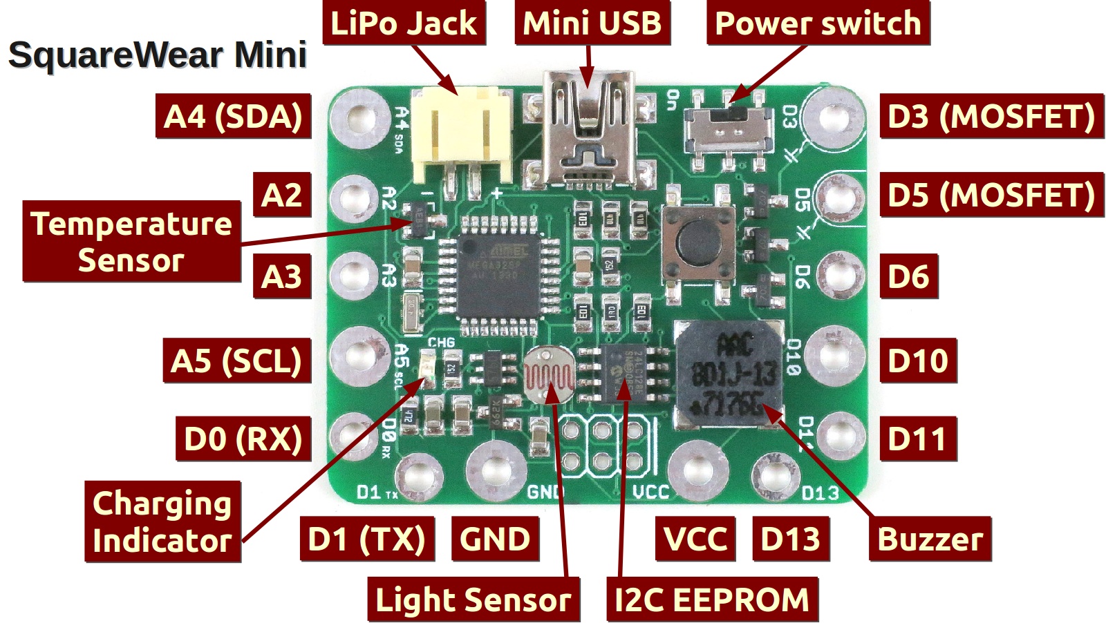
So what is SquareWear Mini? Similar to SquareWear 2.0, the SquareWear Mini is essentially an Arduino running at 3.3V and 12MHz. It is based on the ATmega328 microcontroller, and it has a load of build-in components, including USB port, power switch, pushbutton, buzzer, temperature sensor, light sensor, MOSFETs, lithium battery jack, and lithium battery charger. The pins have enlarged sizes for sewing with conductive threads, for soldering sew-on snaps, and they are great for touch sensing too.

How did I shrink it to be smaller than the original SquareWear? Well, by removing the on-board rechargable coin battery and color LED, and routing some pins to the side. With the space saved, I was even able to add a 16KB I2C EEPROM for storing extra data. Shortly you will see how this is useful. These changes were made because SquareWear designed specially to be attached to a chainable color LED matrix. This will enable a whole new set of exciting projects, as you can see from the video above.
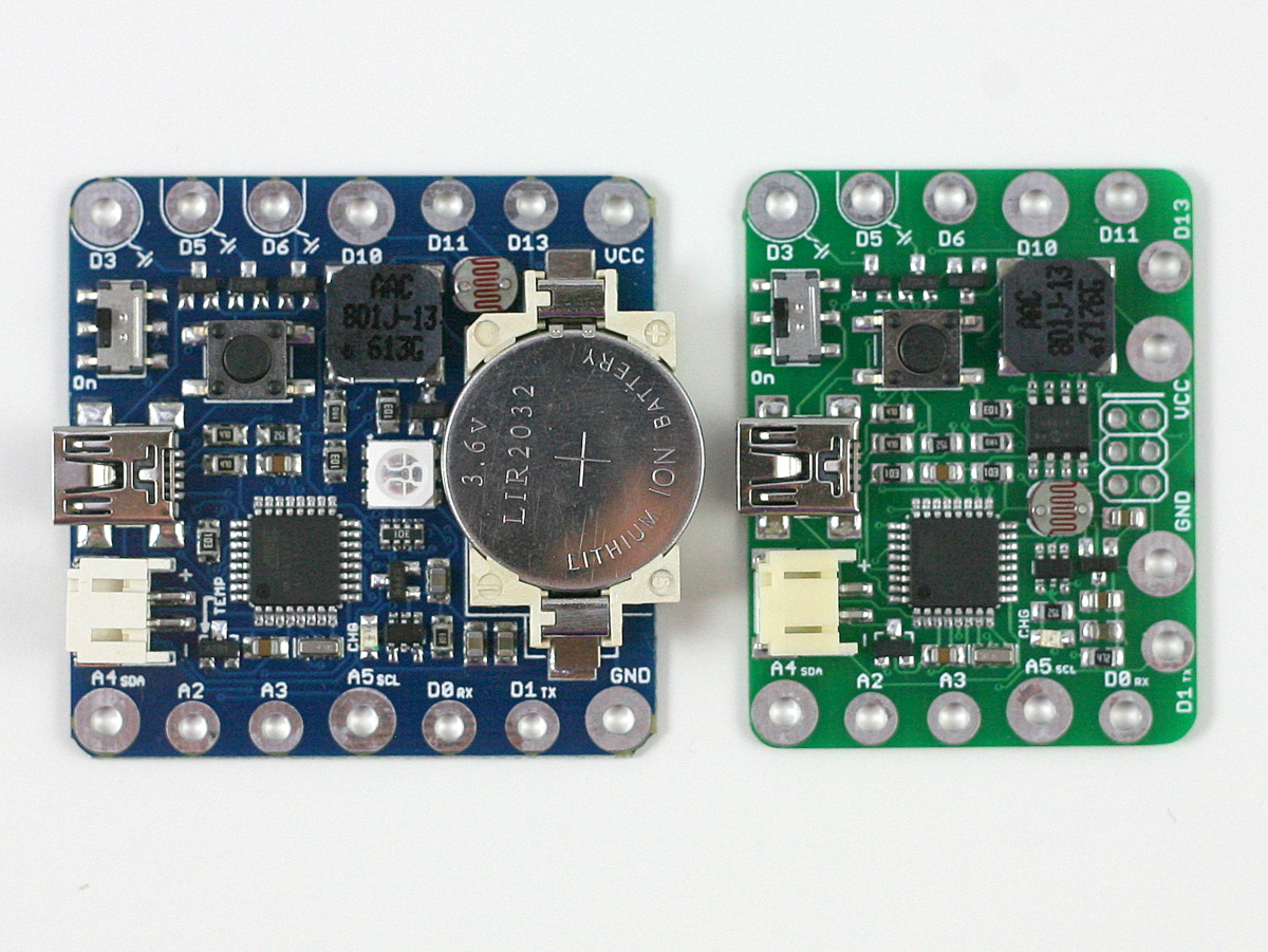
IMG_3015squarewear_mini_annotation

Color LED Matrix

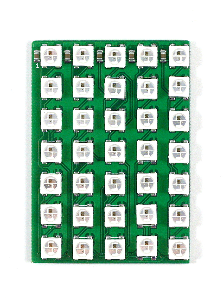
So let me briefly explain the LED matrix. Each matrix contains 35 LEDs arranged on a 5×7 grid with 8mm spacing. It uses the WS2812B color LEDs. These are great because the LED has a built-in chip that allows you to daisey chain them in bulk and still be able to individually set the color of any LED with only one microcontorller pin. Adafruit gave them a name calle the Neopixels. No matter how many LEDs you have, you only need 3 pins to get them to work, namely the VCC, GND, and DATA_IN pins.

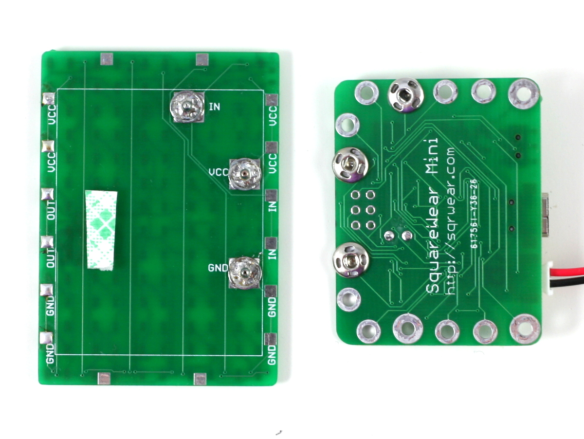
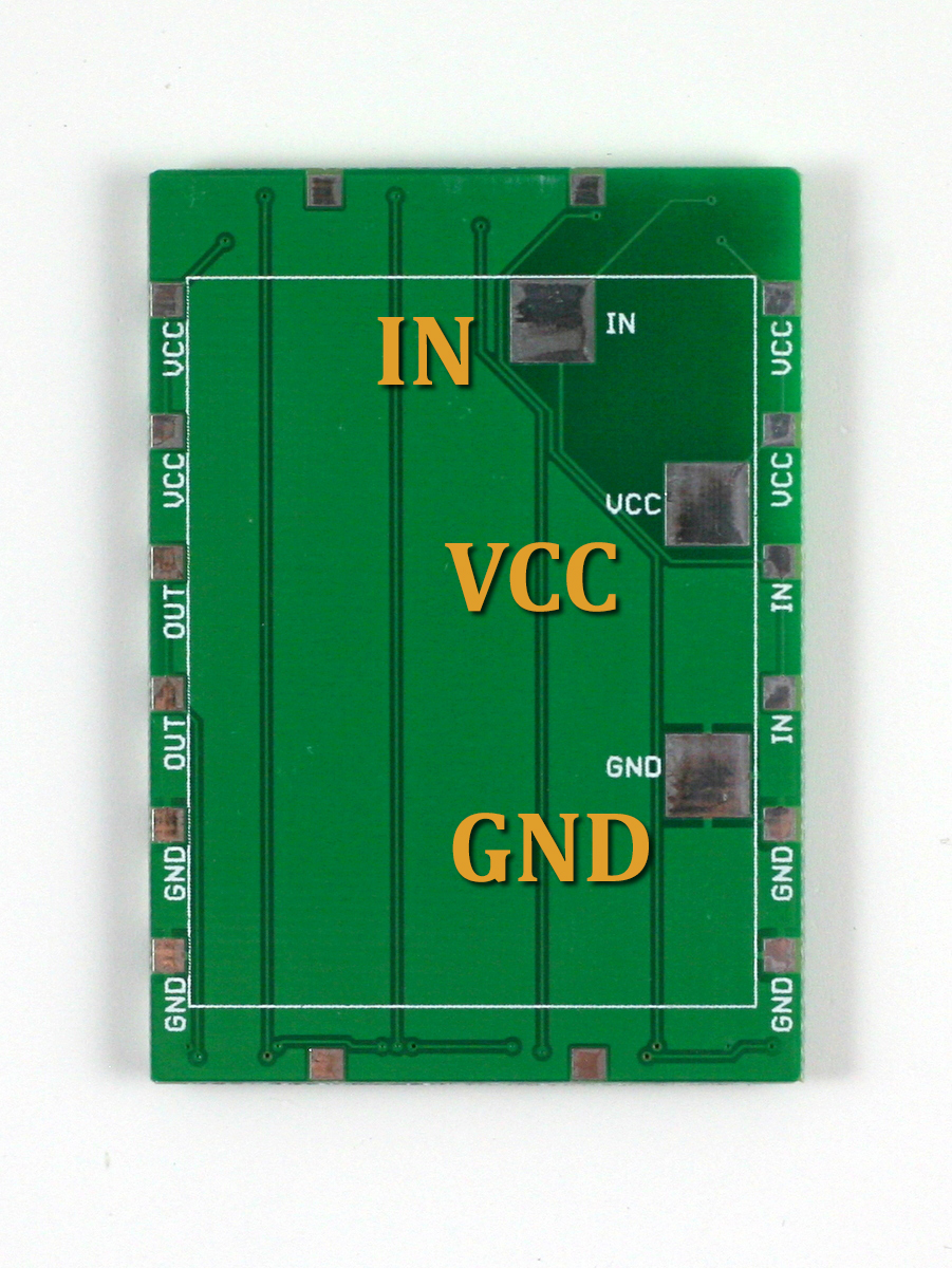
These pins are mapped out at the back of the LED matrix. The locations of these pins exactly match the VCC, GND, and digital D10 pins on SquareWear Mini, so you can easily attach SquareWear Mini with the LED matrix by either soldering some sew-on snaps, or directly soldering the two boards together.
IMG_3048IMG_3049IMG_3033IMG_3037

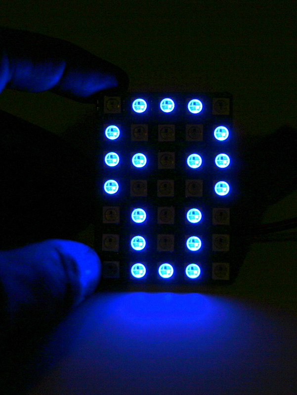
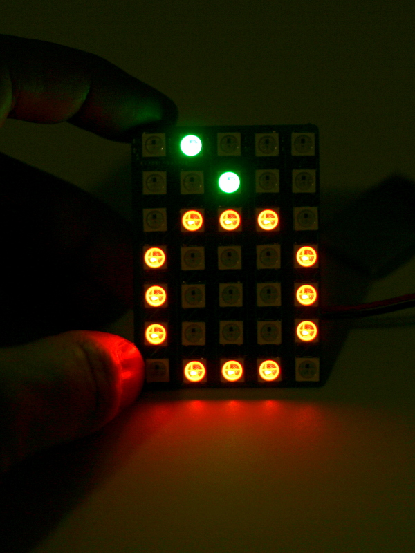
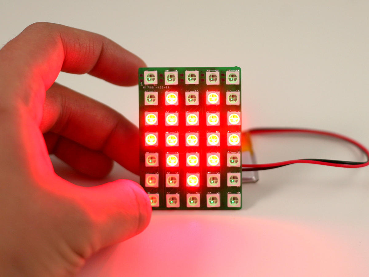
The resolution 5×7 is not a whole lot, but it is sufficient to display ASCII characters and a lot of cute icons:
IMG_3044IMG_3057IMG_3058IMG_3059

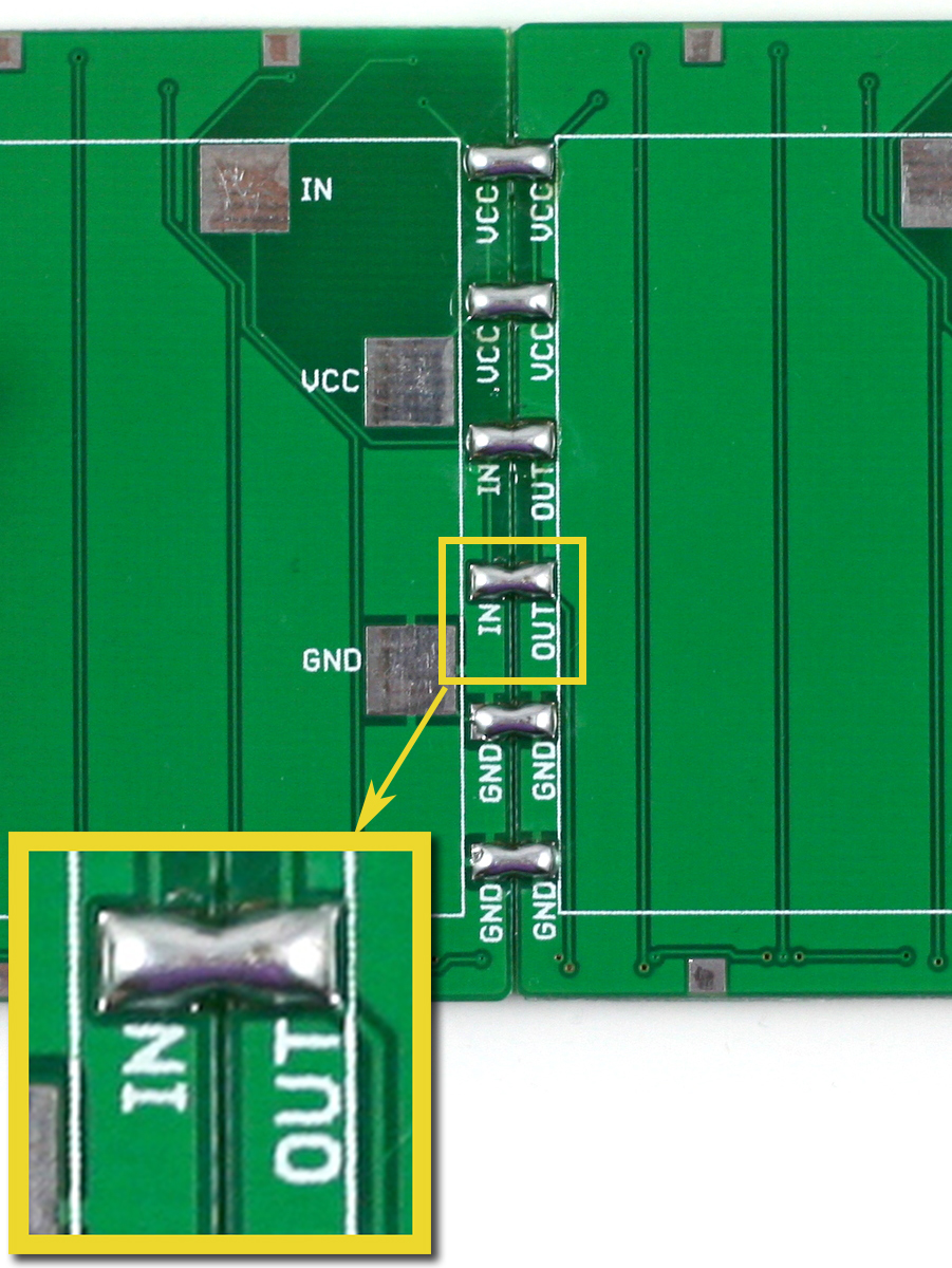
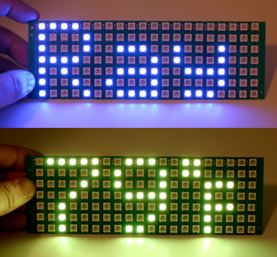
The LED matrix is designed to be chainable too. Each board has DATAIND pins on one side, and DATAOUT on the other side. To extend the number of boards in the X direction, just place two matrices side by side and solder across the 6 pins on the boundary. The solder will get the two boards firmly attached to each other. Chain several boards together to make a large display panel, and it’s great for showing text and messages in any color you want. For example, you can use it as a name tag, or a thermometer (remember, SquareWear Mini has a built-in temperature sensor!)
IMG_3050IMG_3107_comb

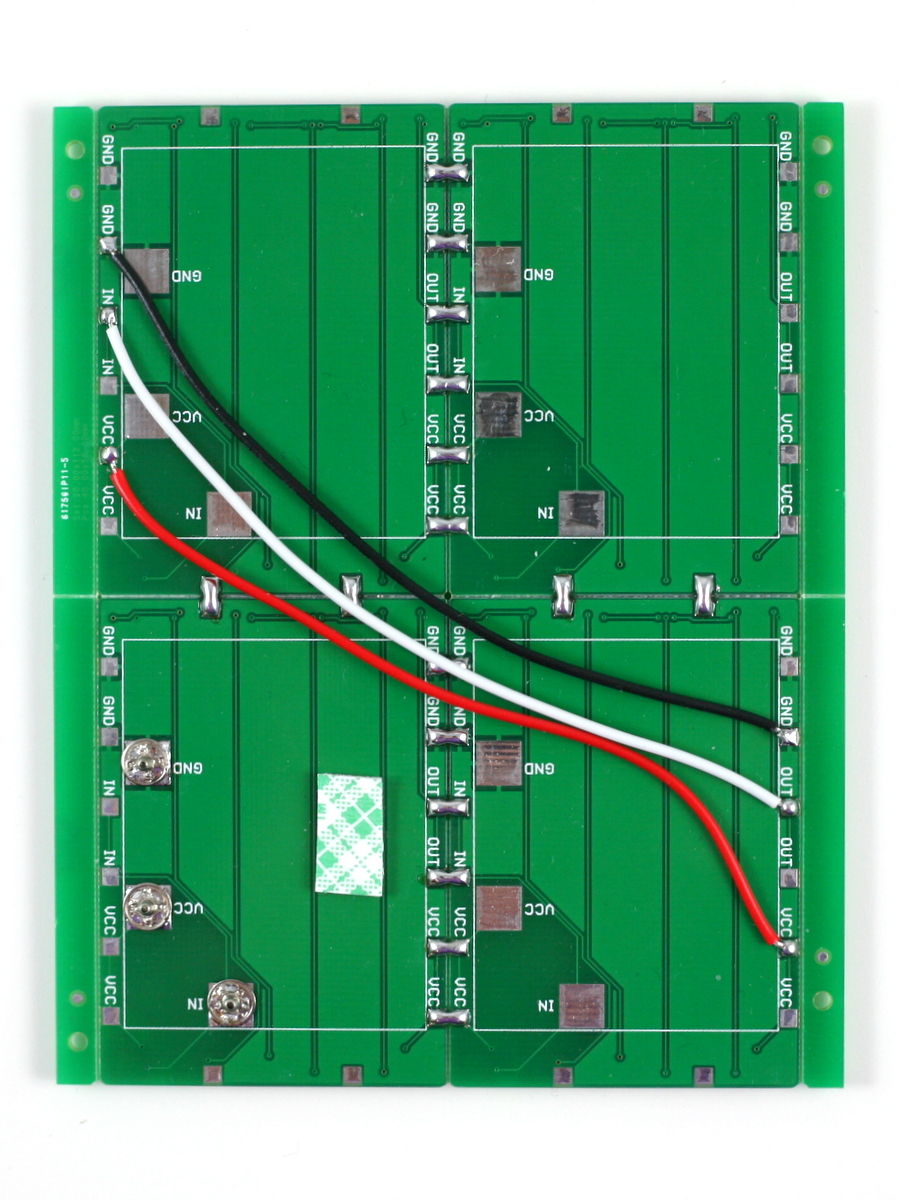
You can also extend the panel in the Y direction. To do so, use three wires to connect the VCC, GND, and DATA_OUT pins of the previous row to the VCC, GND, DATA_IN pins of the next row. Also solder across the pins on the vertical direction to firmly attach the two rows of boards together. There you go, a bigger panel to display more detailed graphics!
IMG_3051IMG_3110

Software Demos

We’ve re-worked the SquareWear software library to include LED matrix demos. These demos work on both the original SquareWear 2.0 and SquareWear Mini. Check the video above for selected examples. The demos are included in the pre-configured software package, and are also available for downloaded individually at the SquareWear Github repository.

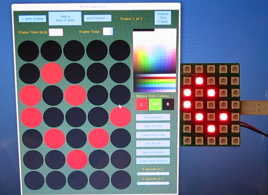
What I want to highlight here is the Flipbook Animation demo. It’s a great demo that allows you to interactively design pixel patterns and even an animation. SquareWear Mini can store the frame data into the I2C EEPROM and play it back later. Even better, it comes with sounds too! So how does this work? First, you upload the Flipbook Arduino code to SquareWear. Then, run the Flipbook host software. The host software is written in Processing and is cross-platform. It uses the HID Serial interface to communicate with SquareWear. In the host software you can click on pixels and assign them color values. These values are immediately transferred to SquareWear so you can preview the frame in real-time. For each frame you can specify the frame time and optionally a music note to play. You can create multiple frames, navigate through each frame, make modifications, save the animation to a disk file etc. At last, when you are satisfied with it, click on ‘Transfer to Device’ and the data will be stored into EEPROM. Next time you turn on SquareWear, just click the pushbutton and it will play back the stored animation. Isn’t that cool? With this tool, you never have to think about converting pixel patterns to programming code any more. Let your creativity and imagination take over!
viscap2viscap11

Hope you like SquareWear Mini, and let us know your cool project ideas!

This past week has been a hectic week. Since SquareWear 2.0 got posted on Hack A Day, things have gone quite wild: we’ve got hundreds of orders, and the SquareWear YouTube video accumulated 80,000 views in just two days. By the end of last week, it has exceeded 100,000 views and has officially become the most popular video at the my YouTube channel.

Among the many emails I received, one common question is what can one use SquareWear for other than the examples demonstrated in the video. Well, at heart SquareWear 2.0 is really just a small Arduino with lots of built-in components (notably built-in rechargeable battery and USB port). The large pin pads make it suitable for wearable electronics projects, and the small size makes it suitable for general-purpose microcontroller projects. For example, I’ve used SquareWear to build a reflow oven controller, a OpenSprinkler Pi tester, a USB-based remote for RF power sockets. It’s really versatile.

If you are looking to make some artistic projects, you will be glad to hear this: SquareWear 2.0 was used at the Mount Holyoke College for their iDesign Studio Class. This class was offered by my friend Audrey Lee last semester, and they’ve just concluded the class last month with a fantastic final presentation. I am going to highlight some of the best projects below. For additional information, check the link above — each project has a website with detailed write-up. I am sure they will inspire you to come up with your own fantastic project idea.

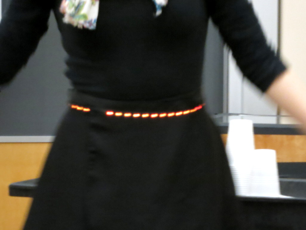
One of my favorite is the Accelexpression project by Madeline Ketley. She combined a SquareWear with a gyro sensor and NeoPixel LED strip to make a smart skirt for dancers. The LED strip displays different colors depending on the standing position of the dancer. It is not only artistic and visually beautiful, but it’s a very useful tool for training dancers: from the color of the LEDs you can easily tell if the dancer is standing straight, or if two dancers are synchronized in their moves. It’s a brilliant idea and I was completely impressed. Here are some rather blurry pictures. I wish I had taken high-quality pictures or even better a video!

IMG_3796IMG_3797IMG_3823

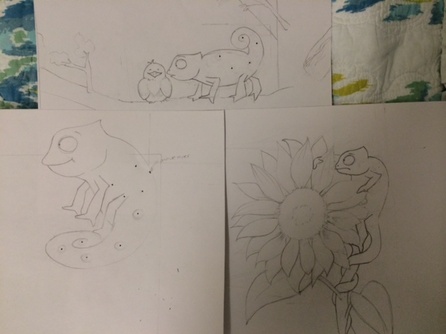
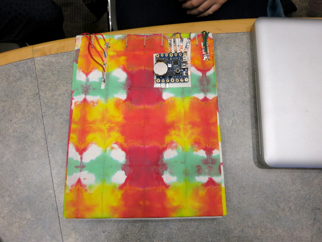
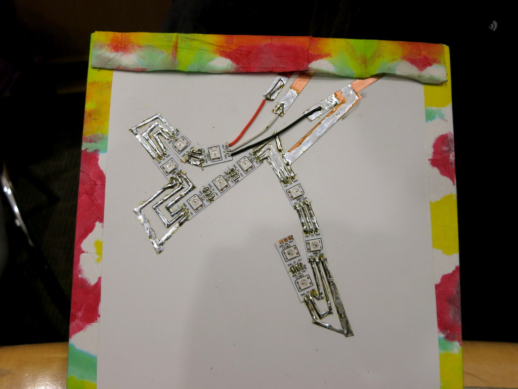
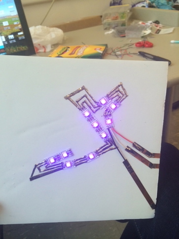
Another favorite of mine is Meaghan Sullivan’s Reading Hardwired. Meaghan made a hand-drawn picture book featuring a timid and cute cameleon. She then combined a SquareWear, copper sheets, some neopixels, and photo-resistors to make the picture book change colors as you turn the pages. It’s so artistic, vivid, and truly brilliant!
IMG_3812IMG_3813

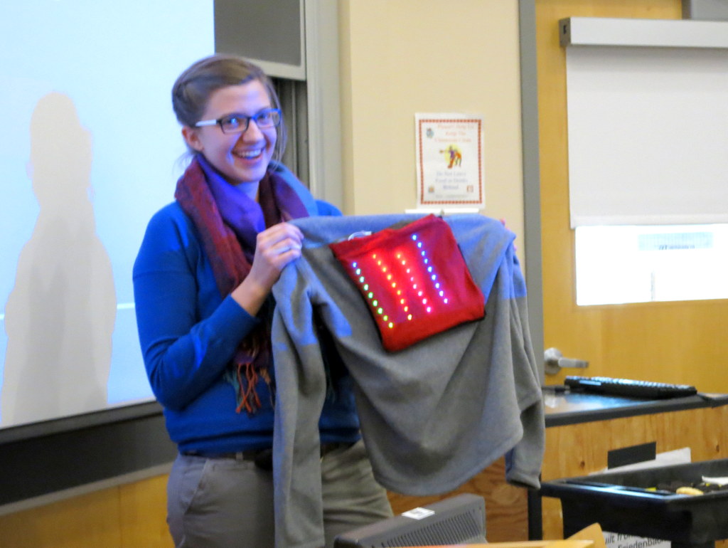
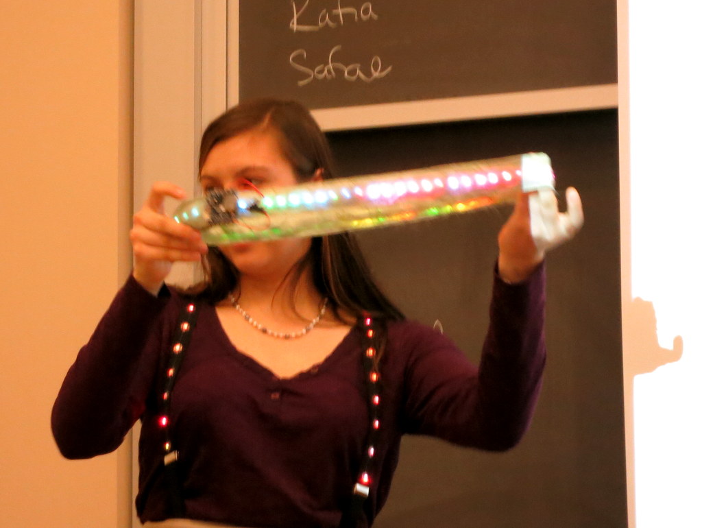
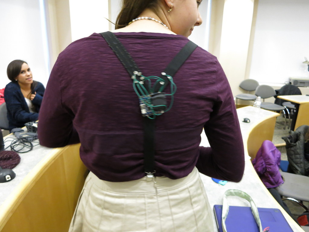
Neopixels seems to be a big hit among students. Alexis Andrus used strips of Neopixels to make a beatuful iDesign Jacket; Ione Brogna also used Neopixel strips to make iTech Accessories, such as these stylish shoulder straps belts. Ione also added a sound sensor to SquareWear and made her iTech accessories respond to music and beats.

IMG_3780IMG_3783IMG_3786IMG_3822

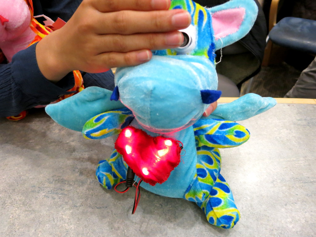
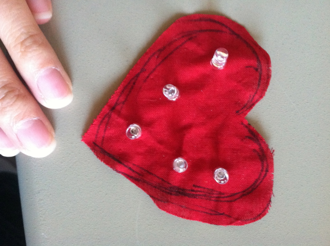
Next up, with Julia Rycyna’s La Coeur du Dragon project, we enter the fantasy land of dragons. She first made a plush dragon with flapping wings using a SquareWear and some muscle wires. Thanks to the build-in MOSFETs on SquareWear, no external muscle wire drivers were needed. Then she added a ultrasonic distance sensor and a LED heart to the dragon, so that the heart blinks faster as you approach the dragon. Quick, hold it tight, how can you bear with putting such a lovely dragon down!

IMG_3807IMG_38202534840_orig

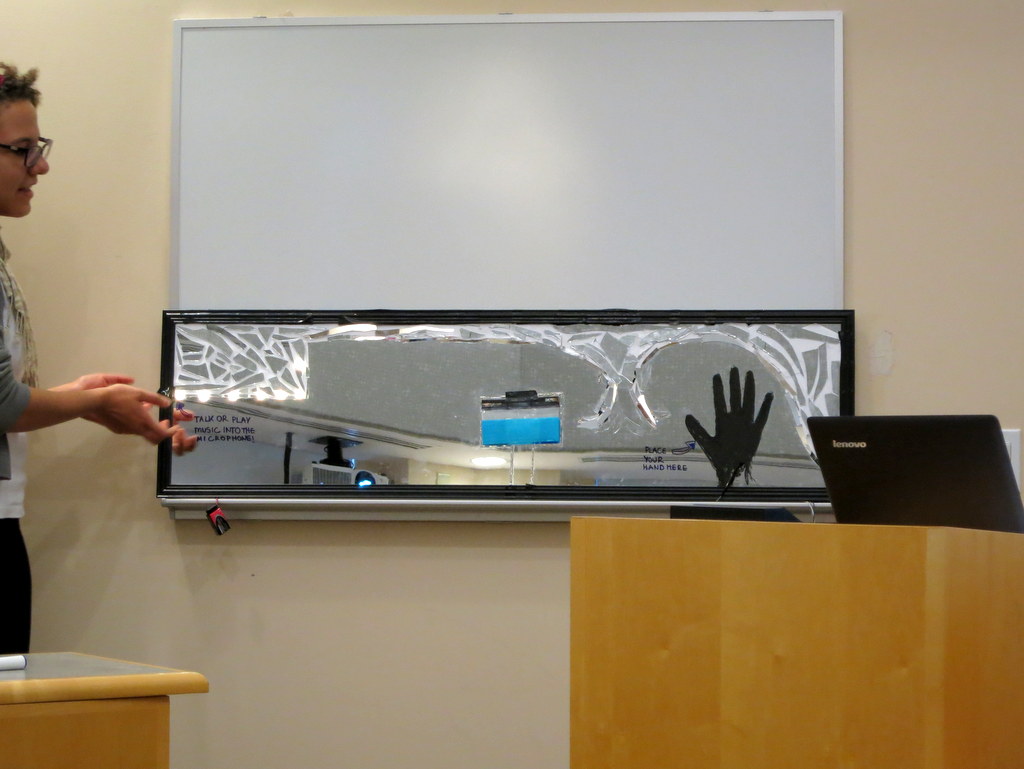
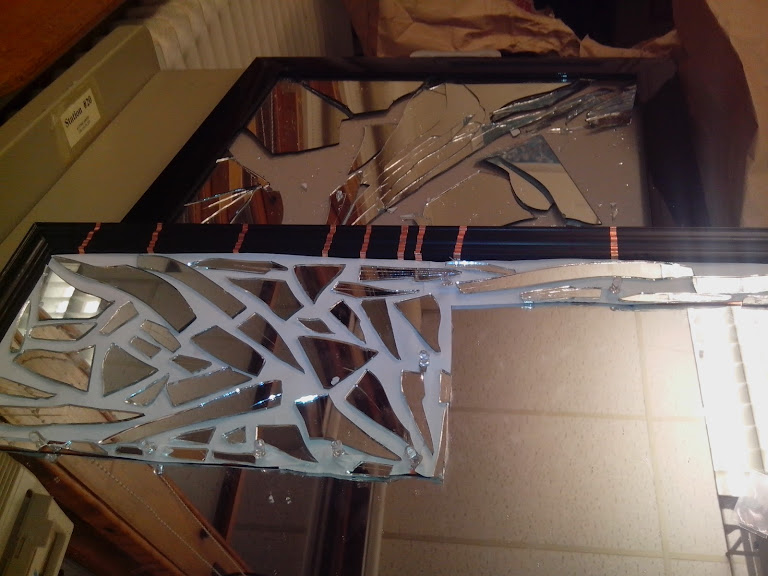
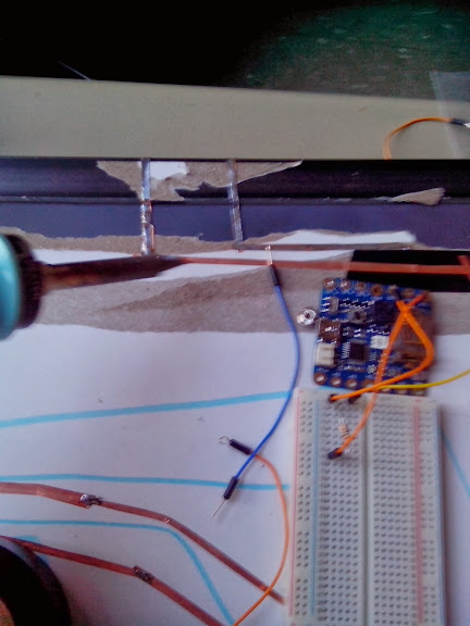
Safae Lahgazi Alaoui presented an amazingly artistic project called the Interactive Mirror. The mirror is decorated with LEDs and responds to sound, touch, and motion. Check the images below and appreciate the complexity of the mirror.

IMG_3802

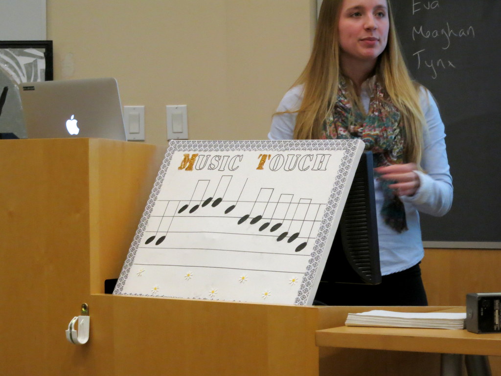
Eva Snyder’s musicTouch project is a great educational tool to teach kids about music and tones. It uses conductive ink and touch sensing to let you play music interactively. If you are interested, be sure to check out my previous blog post about how to use SquareWear to create a touch-based digital piano without any additional hardware.

IMG_3808

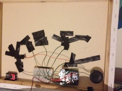
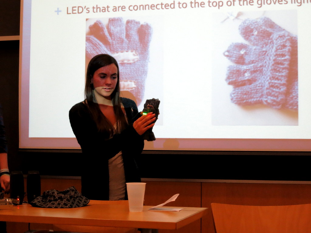
Thinking of some other creative uses of SquareWear? Saadia Gabriel made a solar charging jacket called The Turtle? It makes use of SquareWear to charge a lithium battery, which is then bumped to 5V using a boost converter for charging cell phones. Athena Donta and MJ Lee created the Bad Weather Wear project, which combines a SquareWear, LED matrix, and conductivity sensor onto a pair of mittens. When it rains or snows, the LED matrix displays smileys and different patterns to keep you happy in bad weather. Isn’t that sweet?

IMG_3793IMG_3789IMG_3790

If you are inspired by these projects, consider getting a SquareWear 2.0 from our shop. It’s a great little gadget to help explore the creative and artistic side of you!

Looking for new projects to do with SquareWear 2.0? Here is an idea: combine SquareWear 2.0 with touch sensing to make a digital piano! It works as a standalone project and no additional hardware is required. Take a look at the video first:

How does this work? First, SquareWear 2.0 has a built-in buzzer, so it can already make sound. Next, touch sensing is detected in software. It basically exploits the principle of capacitive sensing: every time you touch an Arduino pin, it slightly alters the capacitance of the pin. This change of capacitance can be detected using a variety of methods. The simplest is to set the pin to digital input mode, and turn on the internal pull-up resistor. This will start charging the capacitor. By detecting the time it takes to charge the capacitor, you can infer the capacitance, and in turn tell if a finger touch has occurred on the pin. That’s it! Because SquareWear maps out available pins to large pin pads, this makes it particularly well-suited for touch sensing.

So I wrote a quick demo as a proof-of-concept. First, I found a function that implements the capacitive sensing from the Arduino playground website. It basically returns a touching sensing value, which can then be compared to a threshold. You may need to adjust the threshold to increase or decrease the sensitivity. The demo scans through all 12 pins available on the SquareWear 2.0 and plays a tone for 125 milliseconds if a pin touch is detected. As a result, the buzzer makes a chiptune type of sound. The code also uses the on-board pushbutton to switch between three octaves: C3, C4, and C5. The LED will blink when a tone is played.

A few notes and quirks:

  • The code works the best if you plug in a USB cable connected to your computer.
  • You can also moisten your figures to help increase the touch sensitivity.
  • If you unplug the USB cable, it generally helps if you use one hand to hold the battery, or the VCC or GND pin. You may need to cover the ISP pins on the back side to avoid touching them. Holding the battery, VCC or GND helps amplify small capacitive changes.
  • The MOSFET pins (D3, D5, D6) do not seem to work well without the USB cable. To be honest, I was surprised that these pins even worked at all, because the pads are not directly connected to the pins (rather, the connection is through a MOSFET). So if you need, you can modify the source code to disable these pins.

The demo code is available in the SquareWear 2.0 software package on Github. The direct download link is below:

I will keep posting new project ideas in the upcoming weeks. SquareWear 2.0 is available for purchase at the Rayshobby Shop. At a price of $22 and with a load of built-in components, it’s a great little gadget to help you learn Arduino programming, and build wearable as well as general-purpose electronic projects. Hope you like this demo and your support is greatly appreciated!

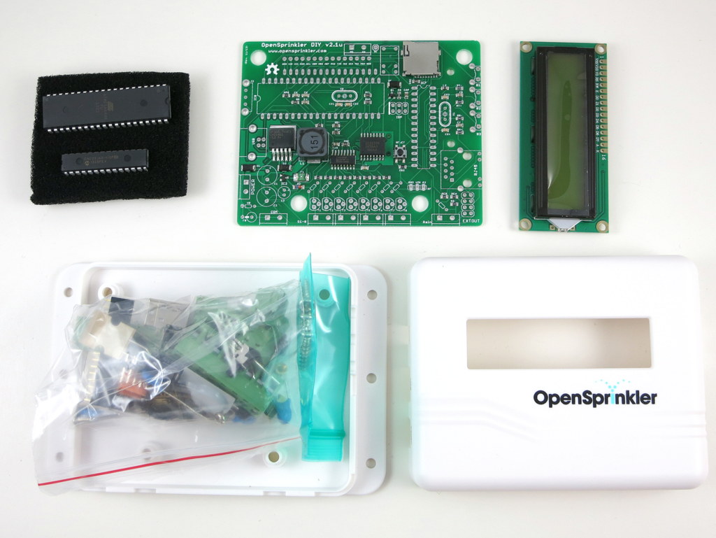
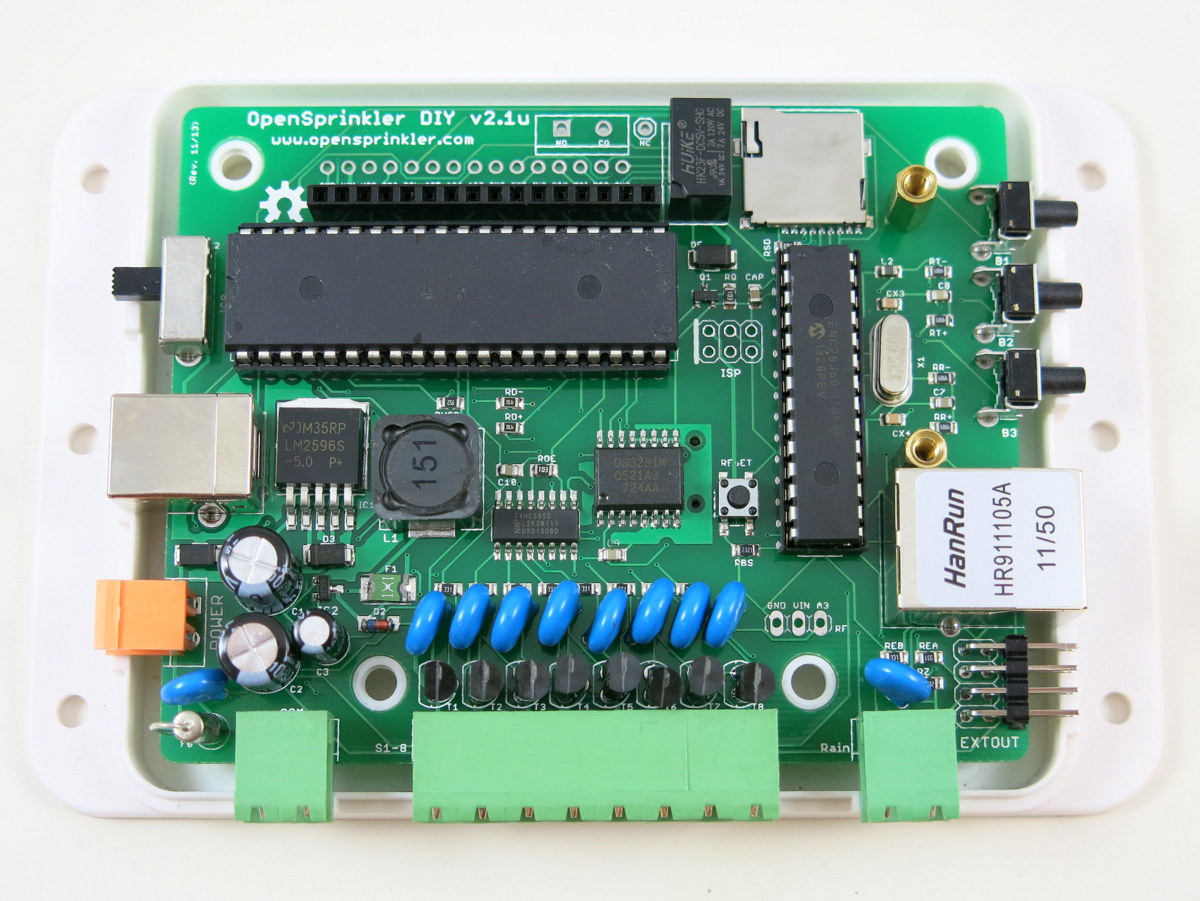
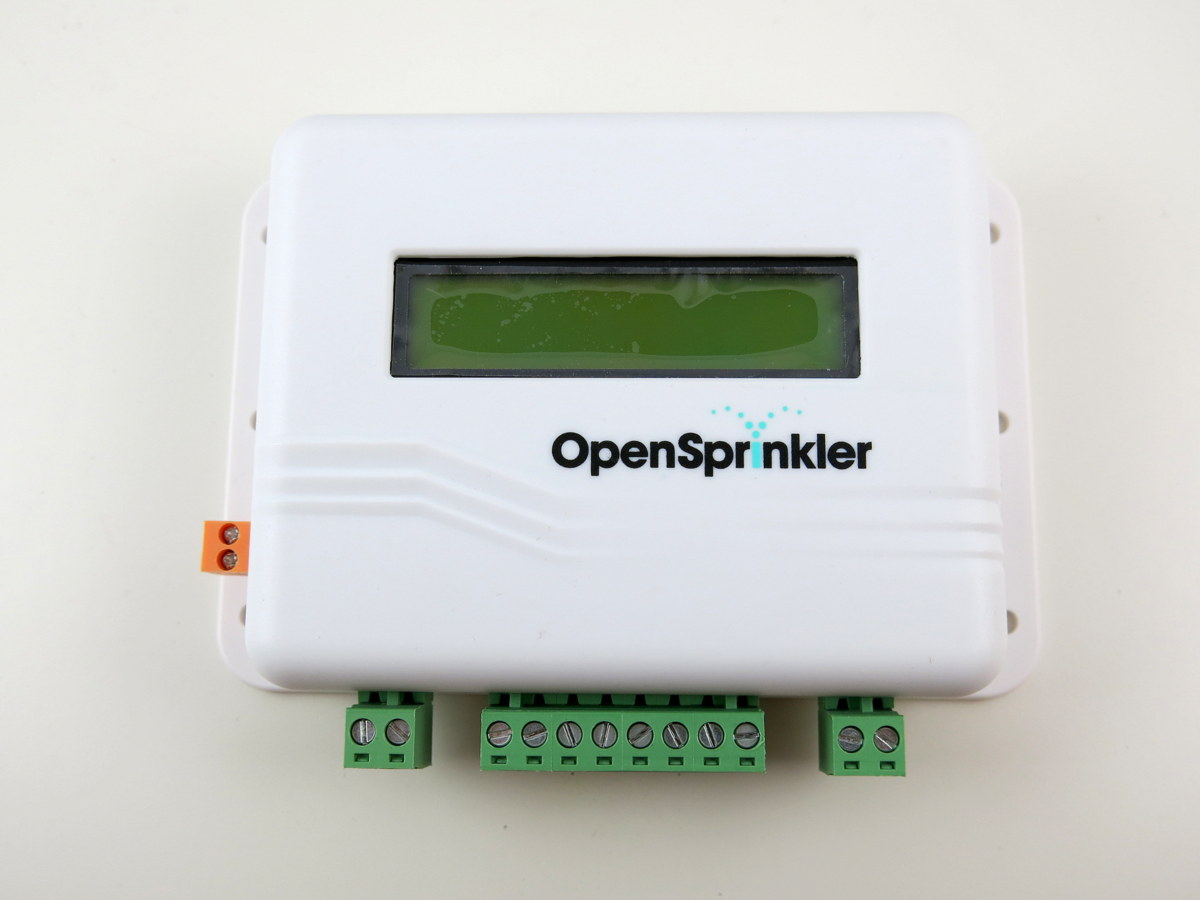
Great news, OpenSprinkler v2.1u semi-assembled DIY kit has now been officially released and available immediately for purchase at the Rayshobby Shop! This version marks a major upgrade from the previous DIY kit v1.42u. With ATmega644 MCU, microSD card slot, and injection-molded enclosure, it not only brings the DIY kit up to speed with the fully assembled v2.0s, but it actually strives to be a little better (hence the migration on the version number) 🙂

In particular, it adds a mini-relay for general purpose switching (similar to the one on OpenSprinkler Beagle), changed the 24VAC terminal to an orange colored one with different pin spacing, and increased MCU frequency from 8MHz to 12Mhz. It also uses a USBasp bootloader built-in on the ATmega644 MCU for firmware flashing (while all previous versions use a separate ATtiny45 chip). The USBasp bootloader significantly improves the firmware upload speed, and is therefore very helpful if you are making frequent changes to the firmware. These changes are all described in the prototype sneakpeak preview post. Finally, the MCU is pre-loaded with the latest firmware 2.0.3 with several new features compared to the previous firmwares.

osdiy_headerIMG_3758

Another notable change is that v2.1u is the first semi-assembled DIY kit which comes with a partially assembled circuit board with through-hole components. I’ve designed it this way to help reduce the amount of soldering you have to do, while still let you enjoy the process of building, assembling, testing, and hacking the circuit. It’s a first-time experiment, so I will keep my fingers crossed.

In any case, if you’ve been waiting for OpenSprinkler DIY kits, go grab one quickly before it’s gone; if you already own an OpenSprinkler or have heard of OpenSprinkler one way or another, I would appreciate if you can help me spread the word. Thanks!

IMG_3762

DS1307 is an old and classic real-time clock (RTC) chip that has been used in many electronic circuits. There are also many libraries written for DS1307, notably this Arduino Time library which includes a DS1307RTC class. Given its age and popularity, it’s surprising that the chip is not cheap: even at volume pricing, it usually costs around $2 each. Even a microcontroller like ATtiny45 costs only about about 60 cents. How complicated can an RTC chip be compared to a microcontroller!

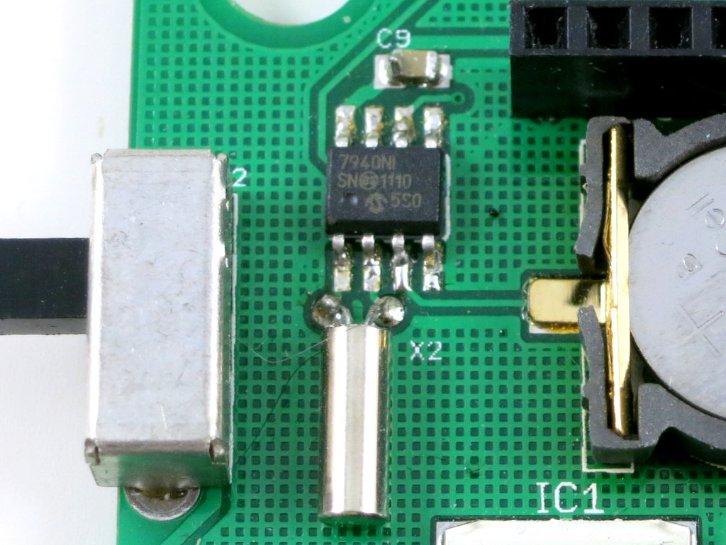
Recently I came across Microchip’s MCP7940N, which is less expensive and is pretty much a drop-in replacement of DS1307. At a quantity of 100, it costs 65 cents each, which is about a third of the price of DS1307. To be fair, there are even cheaper options, but those often do not have battery backup support, which would not be desirable.

IMG_3832

Microchip has published a DS1307 to MCP7940N migration document which thoroughly explained the differences between the two. To begin, Microchip recommends adding a few extra elements, such as load capacitors for 32.768kHz crystal, and protection circuitry for the backup battery. If you are not so concerned with this level of reliability, you can leave out these elements and hence it will be truly a drop-in replacement.

Next, there are a few software changes we have to make, mainly three:

  • I2C address: MCP7940N uses address 1101111 while DS1307 uses 1101000.
  • Clock enable: MCP7940N uses active high while DS1307 uses active low.
  • Battery backup: MCP7940N disables it on startup while DS1307 always enables it.

These changes are fairly easy to make. So I modified the DS1307RTC library to accommodate both. The library can automatically detect which RTC chip you have. Using the modified library, you need to first run RTC.detect() to detect whether an RTC chip is installed and which one it is. The detect() function returns 0 if either DS1307 or MCP7940N is detected, and a non-zero value if an error has occurred. The rest is the same as before.

This library can replace the one included in Arduino’s Time library. Note that it also works for DS3231, which is compatible with DS1307 but with a built-in temperature compensated crystal.

That’s all. Next time you need an RTC, perhaps you will consider using MCP7940N as an inexpensive alternative to DS1307 🙂

« Newer Posts - Older Posts »