Feed on
Posts
Comments

A month with no new post? That’s unacceptable. Since my last trip to Shenzhen, I actually have quite a few new ideas and projects to post about. The thing is there are so many of them that I don’t know which one to start with! Anyways, I’ve decided to put a stop to this. In this blog post, I will describe some work I did a little while back about implementing HID-class serial communication for AVR microcontrollers using the V-USB library.

Introduction

First, let me explain what I am trying to do. As you probably know, V-USB is a very useful software-only implementation of low-speed USB device for AVR microcontrollers. It adds USB functionality for almost any AVR, particularly for those without hardware USB functionality. With this, it’s possible to make a very low-cost standalone Arduino with USB port and without having to use an FTDI chip. I know there is the Arduino Leonardo, which is based on ATmega32u4, and which has hardware-based USB functionality. But mega32u4 only exists in SMT package, and it’s more expensive than mega328 after all. Besides, I am fully embracing the ‘I do it because I can’ spirit, and this is actually a great motivation for me to learn about V-USB.

What do I need the USB for? Mostly for two reasons. One is to flash a program to the microcontroller, so it needs a USB-based bootloader. For this, there is a very nice open-source project called USnoobie, which can bootload mega328 as a USBasp programmer. This way you can flash a program through the USB port directly, without using a serial cable or an external AVRISP programmer. So this is all good.

The second reason to have USB is for serial communication — the ability to transfer data (e.g. strings) in and out between the device and a host computer through the USB port. This is useful especially for debugging (i.e. printing values to a serial monitor), unfortunately this feature is missing in most V-USB projects. There are some related projects. For example, I came across the AVR-CDC project, which turns a mega328 into a CDC-class USB-serial converter. But there seem to be some limitations of using V-USB to implement CDC (i.e. violates USB standard), and also CDC-class devices require installing a driver on Windows. I would like to make a HID-class USB device which does not require driver installation. So overall I didn’t find any available resource that I can use directly.

Circuit Design and V-USB

Now I’ve explained the motivation, let’s see how to go about implementing it. The first step is to learn to use V-USB. I started with the EasyLogger project downloaded from the V-USB website. It is based on the tiny45 mcu. The program reads a sensor (e.g. temperature or light) and presents itself as a USB keyboard to print out the sensor values to a host computer. This is an excellent starting point for me because USB keyboard is a standard HID-class device, and the project is simple enough that I can easily learn and make modifications.

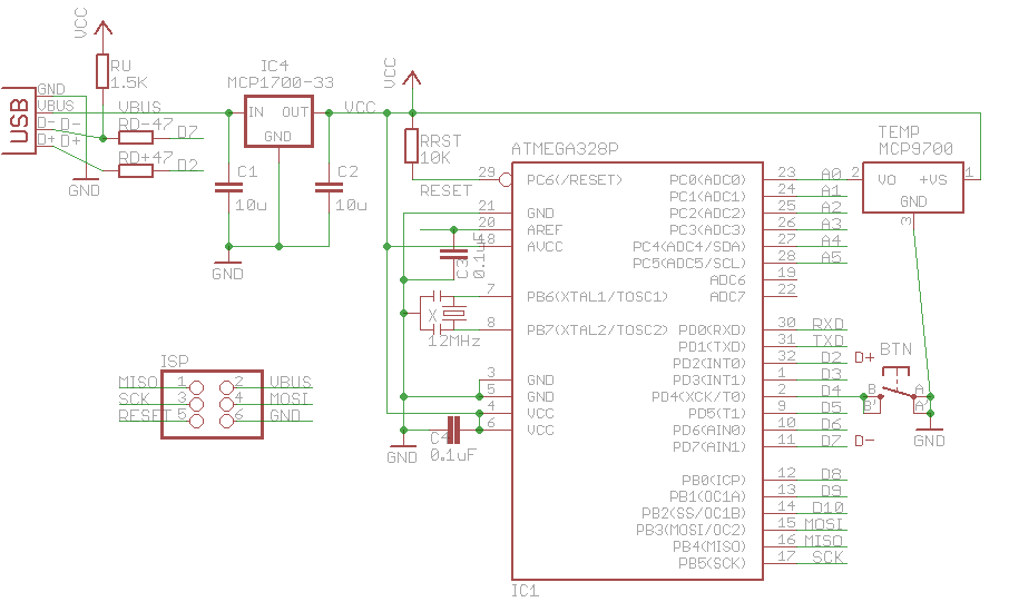
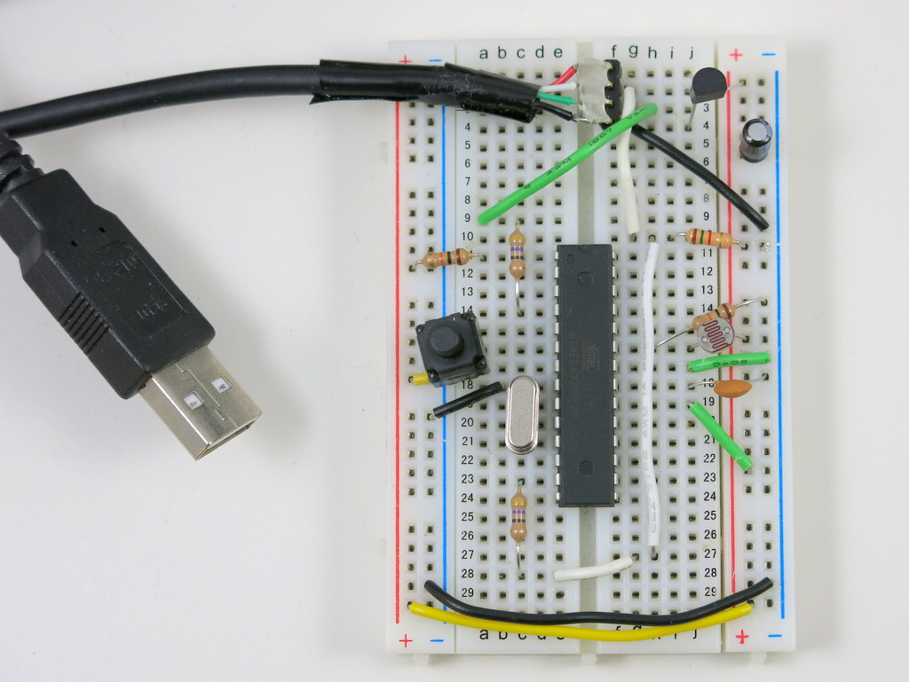
To adapt it to mega328, I first made a circuit based on USnoobie. Here is the schematic and my build of the circuit on a breadboard:
m328-vusbIMG_3287

It’s a pretty standard V-USB setup. I assigned digital pin PD2 (INT0) to USB D+, pin PD7 to USB D-, and PD4 to a pushbutton. The pushbutton is used to enter bootloading mode. Specifically, if the button is pressed when the circuit is powered up, the bootloader is activated and the mcu will appear as a USBasp programmer. Different from USnoobie, I’ve decoupled this button from the D- line, so that I can use the button for general-purpose input (otherwise pressing the button will trigger the D- line). This requires changing the USnoobie code slightly to use pin PD4 for bootloading condition. Finally, I’ve also added a MCP9700 temperature sensor (you can replace it by any analog sensor such as photosensor) to analog pin ADC0 for testing later.

The next step is to modify the source code. First, change usbconfig.h to match the D+ and D- pin settings, specifically the following three macro defines:

#define USB_CFG_IOPORTNAME      D
/* */
#define USB_CFG_DMINUS_BIT      7
/* */
#define USB_CFG_DPLUS_BIT       2
/* */

Next, modify main.c. This step is pretty technical and tedious. It mainly involves changing register names to match mega328 (since the code was originally written for tiny45). Also, the calibrateOscillator(); function can be removed as the mega328 will be running on an external 12MHz clock.

I also modified the Makefile in order to compile and flash the code for mega328. After a few tweaks here and there, the EasyLogger started working on my mega328! It can successfully output numerical values to a text editor through the USB port. This is very encouraging. If these steps don’t make much sense, you can take a look at the code below, and give it a try yourself.

Learning HID

HID stands for Human Interface Device. It’s a USB class designed primarily for keyboard, mice, joystick, and similar human interface devices. The nice thing about HID is that it’s supported on all operating systems. For example, on Windows, the system uses built-in HID driver to handle USB requests, so no driver installation is required. This is why when you plug in a keyboard or mice, you never have to install a driver (imagine how annoying it would be if you had to!).

To implement HID, you first will need to construct a HID descriptor, which describes the number of reports, and the size, meaning, and (optionally) value range of each report. For example, these reports can be the ASCII code of the pressed key, the x and y offsets, and button presses of the mouse. There are also more general-purpose reports like a buffer of bytes. This is what I will be using to transfer bytes in and out between the device and host. To be honest, the whole USB descriptor thing was very obscure to me in the beginning. I didn’t know if there is one correct way to define it, or it can be flexible. As it turns out, Linux is pretty forgiving about it, but Windows is not. After many trials and errors, I finally settled with this HID descriptor:

PROGMEM const char usbHidReportDescriptor[USB_CFG_HID_REPORT_DESCRIPTOR_LENGTH] = {    /* USB report descriptor */
    0x06, 0x00, 0xff,              // USAGE_PAGE (Generic Desktop)
    0x09, 0x01,                    // USAGE (Vendor Usage 1)
    0xa1, 0x01,                    // COLLECTION (Application)
    0x15, 0x00,                    //   LOGICAL_MINIMUM (0)
    0x26, 0xff, 0x00,              //   LOGICAL_MAXIMUM (255)
    0x75, 0x08,                    //   REPORT_SIZE (8)
    0x95, 0x08,                    //   REPORT_COUNT (8)
    0x09, 0x00,                    //   USAGE (Undefined)  
    0x82, 0x02, 0x01,              //   INPUT (Data,Var,Abs,Buf)
    0x95, HIDSERIAL_INBUFFER_SIZE, //   REPORT_COUNT (32)
    0x09, 0x00,                    //   USAGE (Undefined)        
    0xb2, 0x02, 0x01,              //   FEATURE (Data,Var,Abs,Buf)
    0xc0                           // END_COLLECTION
};

It contains an outgoing buffer of 8 bytes (to transfer data to the host) and an incoming buffer of 32 bytes (to receive data from the host). As I said above, Linux is pretty flexible about the descriptor — you can change it in many ways and it still works. Windows, however, is very strict — if you are not careful, it will simply refuse to recognize the device.

The next step is to write functions to handle the USB requests. For transferring data out, I used the usbSetInterrupt function, which allows sending data spontaneously to the host (i.e. whenever the device has something to report). (I should mention here that I wrote the code as an Arduino library called HIDSerial. So everything gets compiled in the Arduino software. You can certainly use avr-gcc to compile the code as well). I made HIDSerial an inherited class from Arduino’s Print class, so I can make use of the many available print functions (e.g. print a string, an integer, a floating point) in the class for serial printing need, without writing extra code. For transferring data in, I implemented the usbFunctionWrite function, as described in the V-USB Document Wiki.

Now, before I can test and debug the code, I need to have some minimal host software to communicate with the device. That’s what I will be describing next.

Write Host Software using Processing

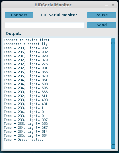
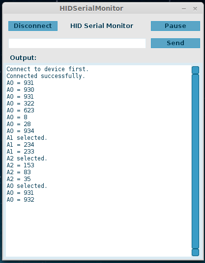
Going the HID route means the device will not appear as a standard serial COM port, so you can’t use the standard serial monitor to send and receive values. Instead, I will have to write host software myself. I can certainly do this in C or Java. But since I want to make the host software cross-platform, I have chosen to implement it in Processing, which allows me to easily export the program as standalone applications on all platforms. Long story short, to do this, I used HIDAPI library. It has all the goodies to handle communications with HID devices, such as finding a device, opening the device, reading from the device, and sending feature report to the device. Also, using the G4P library, you can easily build a GUI with buttons and text fields, and make the interface just like a standard serial monitor. Once the software is finalized, I can simply click on ‘Export Application’, and select all three platforms, and voilà, the host software is all set! Below are two screenshots of the HID serial monitor:
hidserialmonitor1hidserialmonitor2

Source Code

The source code of this project is available for download on my GitHub repository:

You can either do a git clone, or directly download the project as a zip file (see the Download .zip button on the right-hand side of the page). The folder contains circuit schematic, part list, Arduino library (HIDSerial), host software (HID serial monitor), and bootloader (optional, but recommended as it allows you to re-flash the microcontroller through USB, without any external programmer). The Arduino library consists of several starting examples, which are also demonstrated in the video above. I am sure there are bugs and issues with the code, but please feel free to leave comments and feedback below, in order for me to improve the code.

Limitations and Issues

The biggest limitation of this implementation is the data transfer speed — it’s much slower compared to a standard USB-serial converter. This will be an issue if you need to pump out data as fast as possible. But I figured that for the purpose of debugging, the transfer speed is usually not that critical. The software works pretty reliably in Linux, but I’ve found that on Windows, the host software starts to lose data after running for a while, so not all data get transferred correctly. Resetting the microcontroller and restarting the host software seem to get it back to work. I am still investigating the cause of this issue. It may still have to do with Windows being very strict with USB communication protocols. Perhaps the USB experts can take a look at the code and point me in the right direction.

Adapting the Code to Other AVRs

It’s relatively easy to adapt the code to other AVRs. For example, ATtiny45/85 is a popular V-USB platform, since it’s small, cheap, and has internal oscillator that can run at 16.5MHz, which meets the USB standard (so it saves a crystal and frees up two pins). By changing a couple of pin assignments in the source code, I was able to get the HID serial functions to work on tiny45. I really should do it on tiny85, since tiny45 has only 4KB flash space (even a simple demo would take more than 3.5K flash space). Here is a picture of the tiny45 breadboard build. You can even program tiny45 in the Arduino software by following the descriptions here.
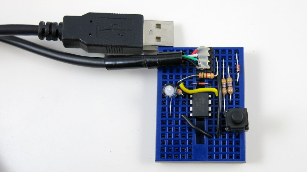
IMG_3322

Thanks for reading the post. Feedback, comments, and questions are welcome.
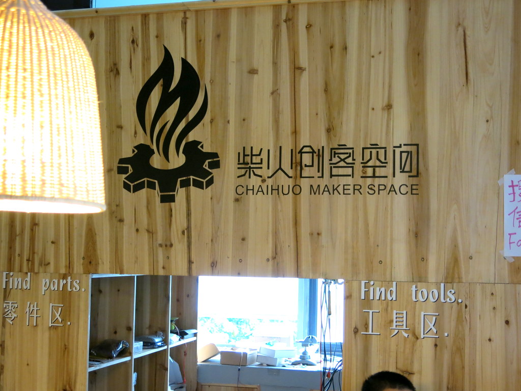
On the last day (Sep 8) of my trip to Shenzhen, I came across a scheduled event at ChaiHuo Maker Space. ChaiHuo is sponsored by SeeedStudio, and the name means ‘wood fire’. As a Chinese saying says: everybody adds firewood, the flame shoots higher. Chaihuo Maker Space is a place to inspire people to come and add ‘innovative ideas and projects’ to the maker culture. SeeedStudio made a very nice Makers’ Map for Shenzhen visitors, where you can easily locate all the maker-related resources and facilities.

IMG_3254IMG_3252

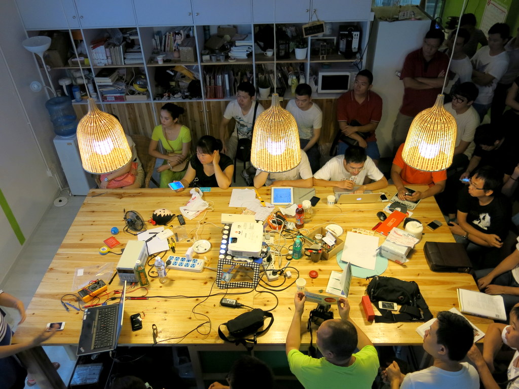
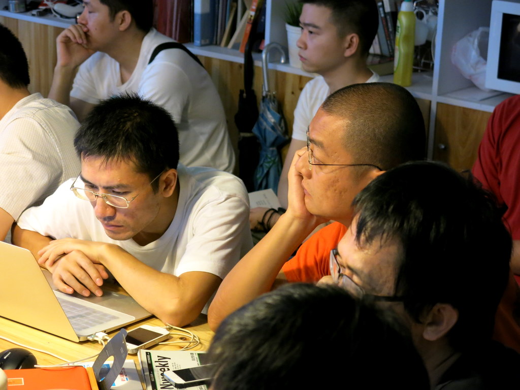
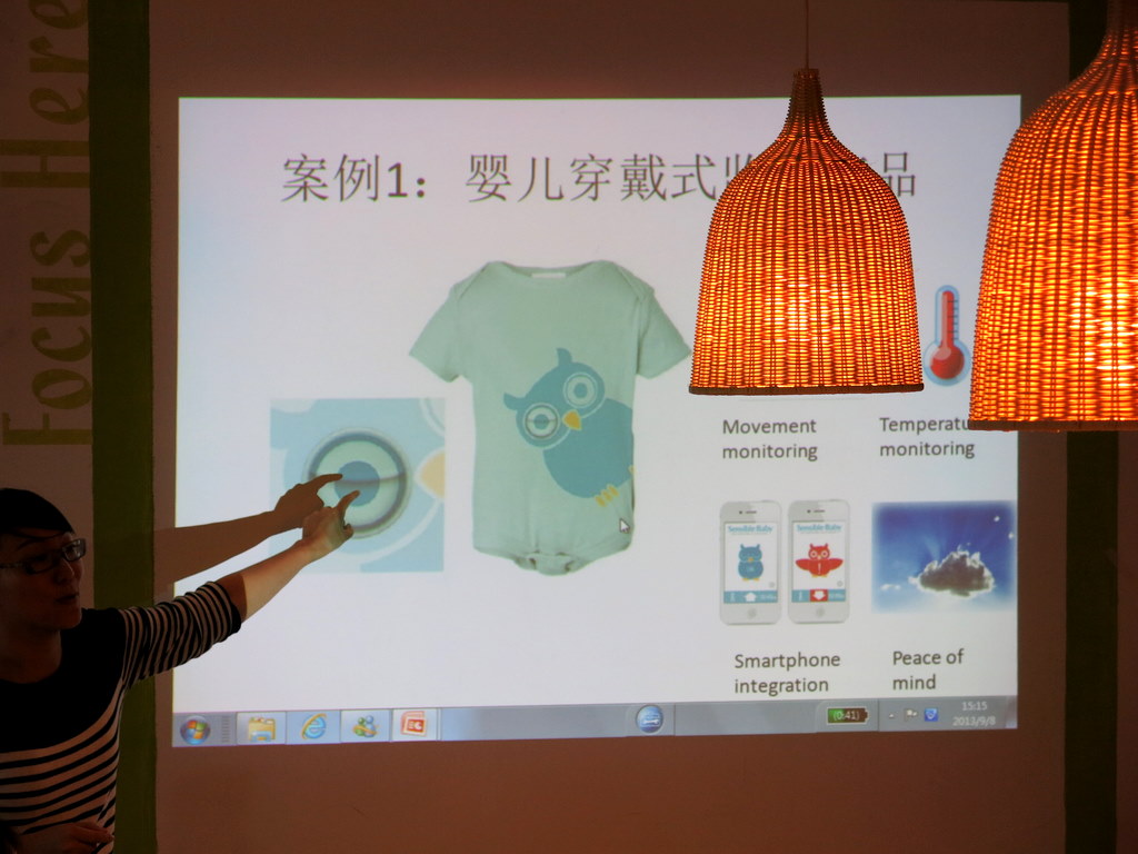
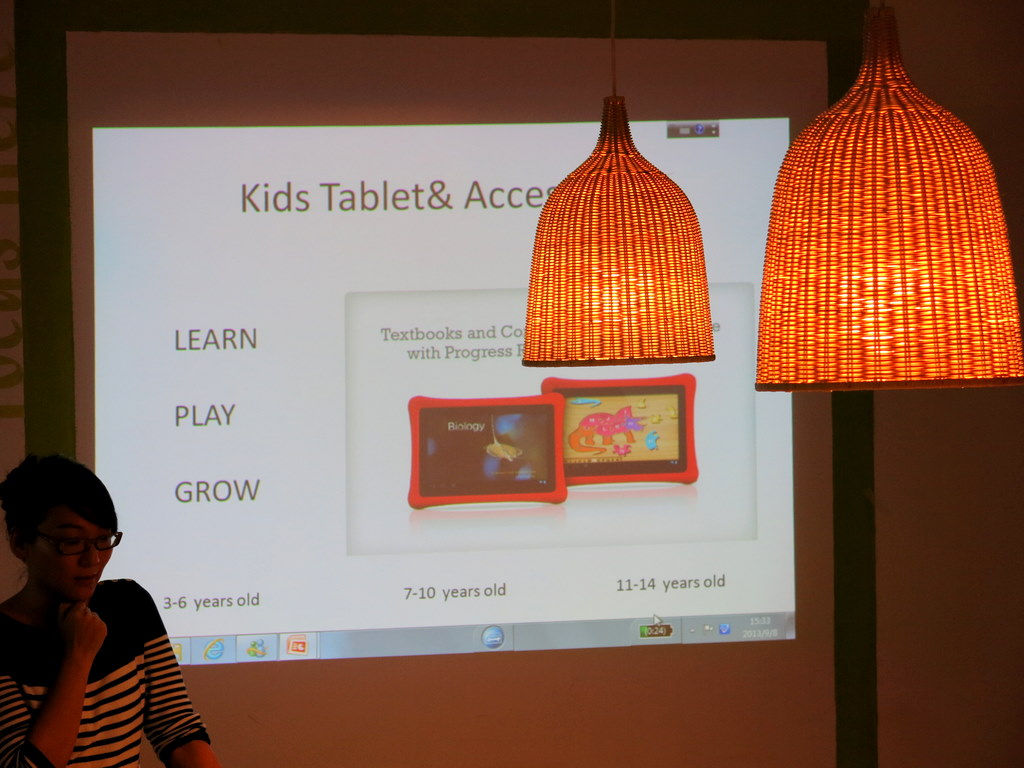
The topic of the event was about innovative ideas for electronic toys. There were 25 to 30 or so attendees, some traveled as far as from Beijing to come for this event. After a brief introduction, the presenter, who is a designer and has extensive expertise in the electronic toy industry started telling us about the lucrative market for electronic toys, the background, challenges, and four recent successful products. Ample time was given for brainstorming and discussing successful tips. This was overall a relaxed and fun event, and a great social opportunity. Many of the attendees were industrial designers and product developers. It’s a palce to make friends and connections.

Speaking of making friends, if you haven’t heard about this, you really have to check out this software app called WeChat (in Chinese it’s called WeiXin ??). I only got to know this shortly before I took off for the trip. Basically WeChat is a free mobile text, voice, and multimedia messaging service. You might think it’s not that different from other mobile texting services, but the power of it is in the user interface and experience, and the fact that it’s very easy to share words and images with your friends. It kind of combines multimedia texting and social network, but it’s very lightweight and much easier to use than Facebook. At the ChaiHuo event, I noticed that everyone was adding friends on their phone using WeChat. It’s amazing to learn that WeChat has already achieved more than 300 million Chinese users and 100 million International (i.e. out of China) users. Next time, don’t bother distributing business cards any more — just use your WeChat app to scan others’ WeChat QR code 🙂

IMG_3253IMG_3250

IMG_3249IMG_3251

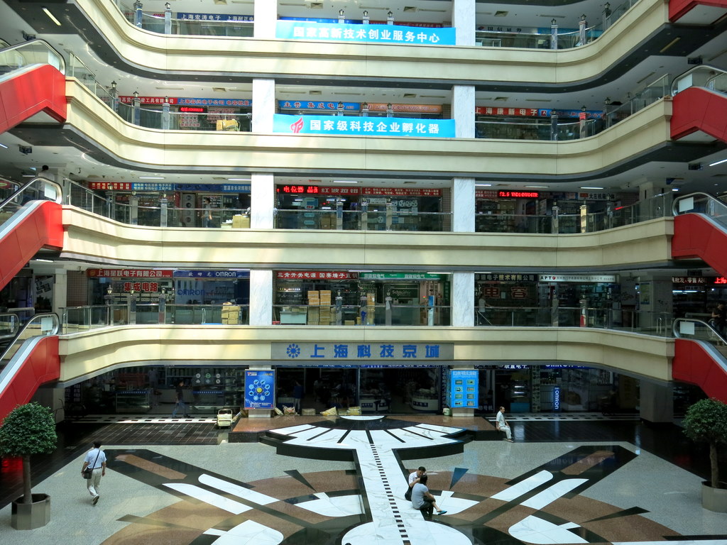
So this concludes my Shenzhen trip. Following ShenZhen, I stayed at Shanghai for one day and visited the electronics market there. It’s prosperous but nowhere near the size and variety of Hua Qiang Bei at Shenzhen. All right, time to pack and go back to the US. Felt like I’ve refreshed myself and gained new energy and inspiration to keep working and innovating :).

IMG_3270IMG_3269

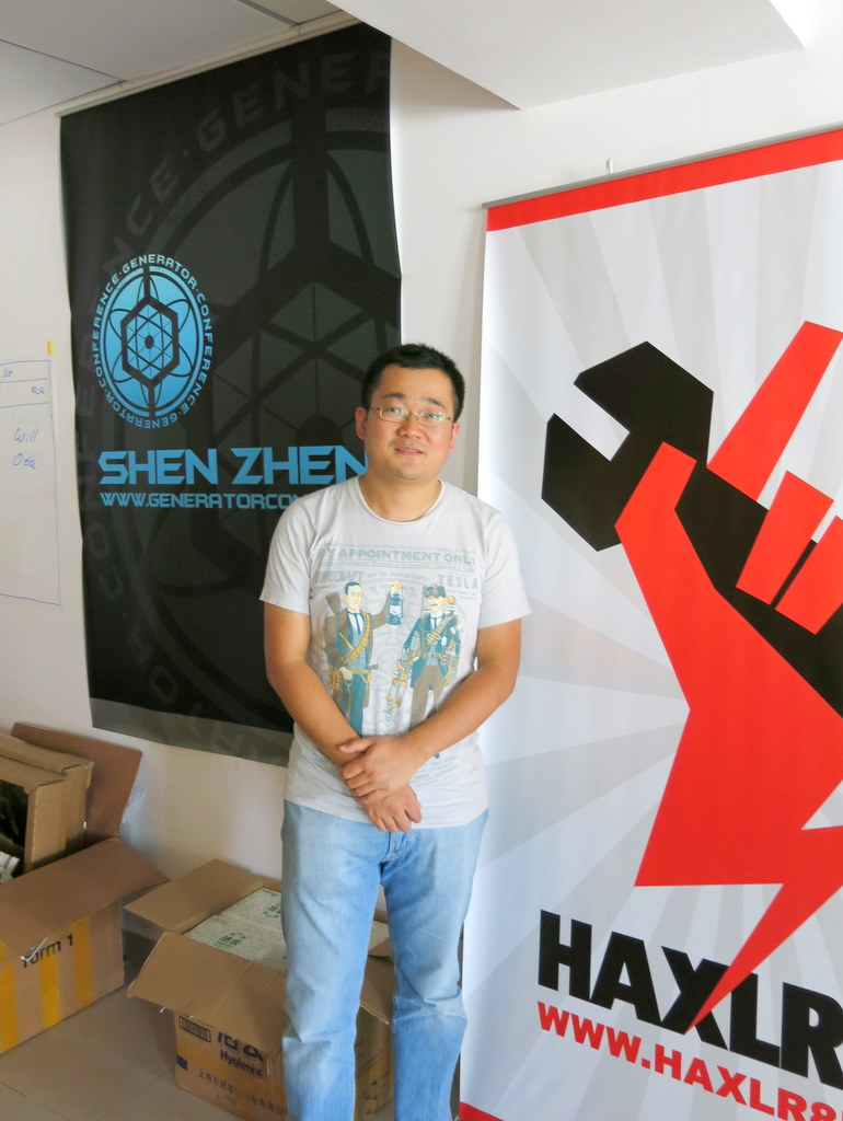
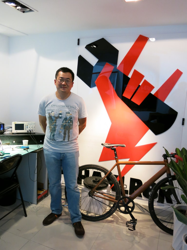
Day 4, I paid a special visit to HAXLR8R. HAXLR8R provides seeding fund to entrepreneurs who are passionate about building hardware devices. It offers $25K funding, office space, access to equipment and tools to a team of startups, in order to help them convert great ideas to functioning and marketable final products. They are very conveniently located right next to Hua Qiang Bei electronics market. Since I’ve met the co-founders Cyril and Zach at the Maker Faire previously, I contacted them through email and they were generous enough to spare some time to meet me.

Here are two pictures I took at the lobby:
IMG_3212-1IMG_3210-1

At the moment they are in the middle of a session with 10 teams. This session will conclude in November. Everyone seems to be very busy, working in deadline mode. I had a great conversation with Cyril about the background of HAXLR8R and his own stories living in China. Being located right next to Hua Qiang Bei makes it super convenient to rapidly prototype ideas — the components and parts you need are within walking distances. Not only electronic parts, but plastic parts, mechanical parts, enclosures, common or uncommon, can be easily made here. It’s THE central place where physical goods are made.

Since everyone seems to be fully engaged in making their products, I didn’t want to take too much of Cyril’s time. After showing him my OpenSprinkler and SquareWear, I took off and headed to the next destination, which is to have lunch with Zach (a.k.a Hoeken). Zach is a fun guy and has been living in Shenzhen for more than two years. He is fascinated by the life in China, and his Mandarin is very good 🙂 At the moment he is in the process of moving to a new place. When I met him, he was visibly tired from late night working. We had a wonderful chat about his life in China, his passions, projects he worked on, the MakerBot (he was one of the original co-founders of MakerBot), the open-source culture, technical stuff, and so on. I felt very excited that we were brought together by this ‘Make’ connection — it’s a great way to meet people.

IMG_3208-1

Feel like I am having a hard time keeping my eyes open now. Will go to sleep soon. Tomorrow is Saturday. I will take a day off to go to the beach with my friend. Will blog again on Sunday 🙂

Time flies. Yesterday was day 3 of my visit to Shenzhen. I went back to SeeedStudio and worked with the engineers on improving the design we talked about during day 1. Here I will give you a sneak peak preview of what’s happening.

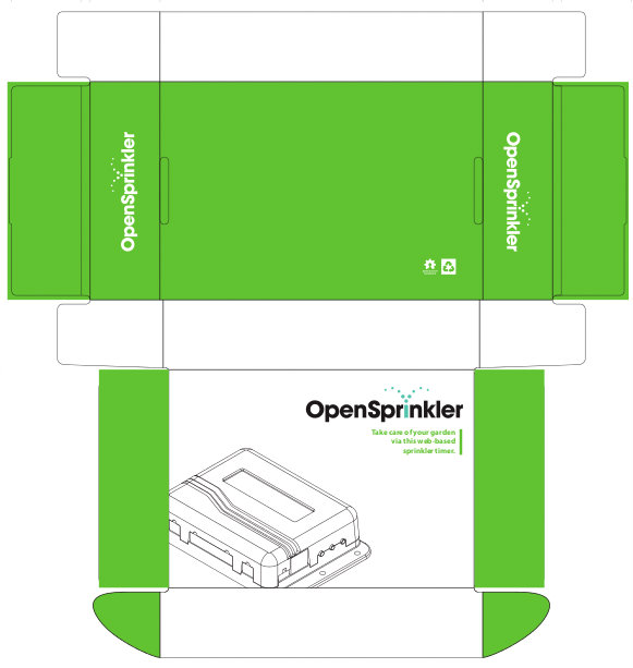
First, we are going to design a paper box for OpenSprinkler. The design is largely based on SeeedStudio’s classic paper box, with art work and color adapted to OpenSprinkler. The first prototype is shown below. It’s pretty simple but it looks pleasant. I should mention that we are designing the paper box mainly because we would like to make this more towards a commercial product, for example, a product that you may find on Amazon.com. So we need proper packaging to give it the professional look and feel. But don’t worry, it will remain an open-source product — no matter how commercial it may be, the open-source nature won’t be lost.

ospaperbox_protoos21circuit

Next, we are also designing an injection molded enclosure for the OpenSprinkler Zone Expansion Board. As the circuit design of the zone expansion board has more or less finalized, I think it’s time to make a custom enclosure for it as well. I don’t have a copy of the prototype design yet, but one of the main changes is that the new expansion board will fit 16 stations per board, and yet the size is approximately the same as the current expansion board (which fits only 8 stations per board).

If you are wondering what about OpenSprinkler Pi — we won’t be designing an injection molded enclosure for OSPi yet, mainly because I heard from grape vine that there will be another round of revision for Raspberry Pi, and I have been advised not to finalize the design yet. On the flip side, I am working on a BeagleBone Black version of OpenSprinkler (for now, let me refer to it as OpenSprinkler BeagleBone). It occurs to me that BeagleBone Black is probably a more suitable platform for sprinkler applications, particularly because it has built-in ADC and RTC. This would make the extension board design really simple. The circuit should be very straightforward, but I do have to spend some time re-working the enclosure design. Will keep you updated about the progress.

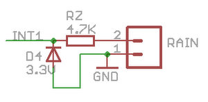
With respect to hardware revision of OpenSprinkler v2.0, there will be a couple of minor changes to address some of the engineering issues. One is a circuit-side protection to prevent the users from damaging the mcu even if they plug in 24VAC into the rain sensor port. This is a rare situation, but because the rain sensor port uses the same type of terminal block as 24VAC, a careless mistake will clearly fry the mcu. The simplest solution we came up with is to add a zener diode and a resistor to the rain sensor port, such that even if you apply 24VAC to the port it won’t damage the mcu’s pin. See the circuit diagram on the right above.

This is fairly standard, so I won’t dwell much on it. But I do want to mention that the resistor RZ should be selected carefully. On the one hand, it should limit the current through zener diode D4 when 24VAC is applied to the terminal. Assuming the zener diode can sustain 10mA, and the maximum instantaneous voltage is 40V DC, RZ should be no smaller than (40-3.3)/0.01 = 3.7Kohm. On the other hand, the rain sensor port has to preserve its normal function, which is to sense the connection / disconnection of the rain sensor. Because we make use of AVR’s internal pullup resistor, which is approximately 20Kohm, in order for the mcu to detect that pin 2 on the terminal is shorted to ground (pin 1), the resistor RZ should be chosen such that 3.3 * RZ / (20K + RZ) < 0.6 where 0.6 is the maximum voltage that appears as a logic LOW to the mcu. So RZ should be smaller than 5.2Kohm. Combining the two factors together, I've chosen RZ to be 4.7Kohm, which falls in the range in between. Another minor change in the plan is to add a few components for AC current sensing, in order to detect the AC current supplied to the solenoids. This is useful for two purposes: one for detecting defective solenoids (i.e. current draw exceeds the typical current draw of a typical solenoid; the other purpose is for monitoring the number of valves that are currently open, which can be done by simply checking the total current draw. In any case, this will be a fairly simple thing to add to the revised circuit. At the end of the day, a friend of mine and I went to a traditional Beijing style hot pot restaurant. Instead of using an electric burner, the traditional style hot pot uses a pot that runs on burning charcoal. It gives the food a nice 'smoked' taste, which is what you won't find in standard hot pot. The food was delicious, and I highly recommend trying it, at least once in your life :) So much for the report today. More to follow tomorrow! IMG_3207-1

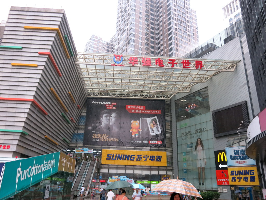
Continuing my last post about this week’s trip to ShenZhen, today’s agenda is to visit Hua Qiang Bei (HQB) — the largest electronics market in the world. HQB is located close to the center of the city. The name literally means the north of the Hua Qiang street. The area spans several big buildings, each of which is full of counters and booths selling all sorts of electronics components and gadgets.

After coming out of the metro HQB station, the first building that came into my eyes is this one:

IMG_3193IMG_3194

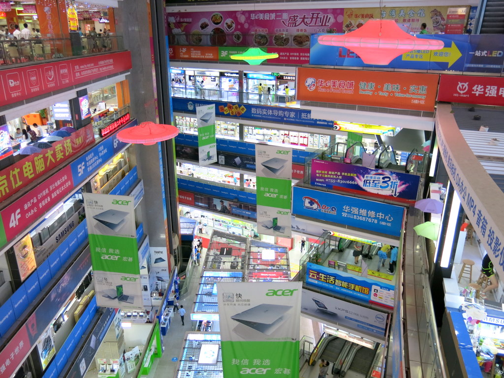
The banner says Hua Qiang Electronics World. Sounds like a place I should be, so I headed right in. Turns out this section of the building is mostly selling laptops, mobile phones, and commercial electronics gadgets. A bit disappointing. However, I discovered that the top two floors are dedicated to LEDs, which is one of the things I am looking for. As soon as I went up, I was faced with a sea of LEDs. There are just too many of them: some are for home lighting, illumination, some are for decoration. Many of them are color LEDs, displaying fancy moving patterns. It’s really awesome. Most sellers here are only interested in customers buying in large quantity. So if you tell them you are buying less than a hundred, they tend to lose interest right away and give you the ‘go away’ look. Some sellers do have the patience of talking to you and listening to what you do. I would rather patron these sellers 🙂

IMG_3195IMG_3196

One of the LEDs I was looking for is of type WS2812, which is used by Adafruit on their Neo Pixels. This type of LED has a built-in IC which allows you to set the brightness of each color separately, and most amazingly it takes only one data pin. You can also cascade multiple LEDs. The data is sent in like shift register, and it gets latched on each LED. This is really a very smart design: with only one data pin, you get to control mutiple independent LEDs, and it requires minimum mcu cycle to operate. Many sellers that carry this product sell them in the form of fully assembled tapes of LEDs; a few do sell just the LEDs, at a price of about $110 for a bag of 1000. Sounds like a competitive price. Short of a reference price, I decided to look around and come back to buy when I feel ready.

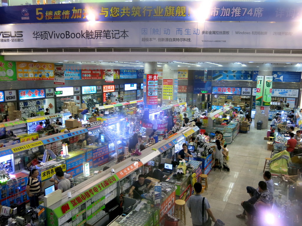
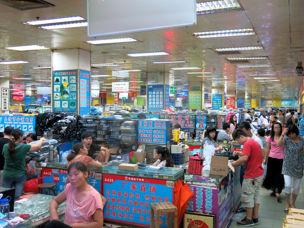
The next stop is the ‘Q’ section of the building, which is dedicated to all electronics components. When I walked into this section, it feels absolutely like a heaven for electronics lovers. There are endless counters that sell all sorts of components that you can think of.

IMG_3197IMG_3200

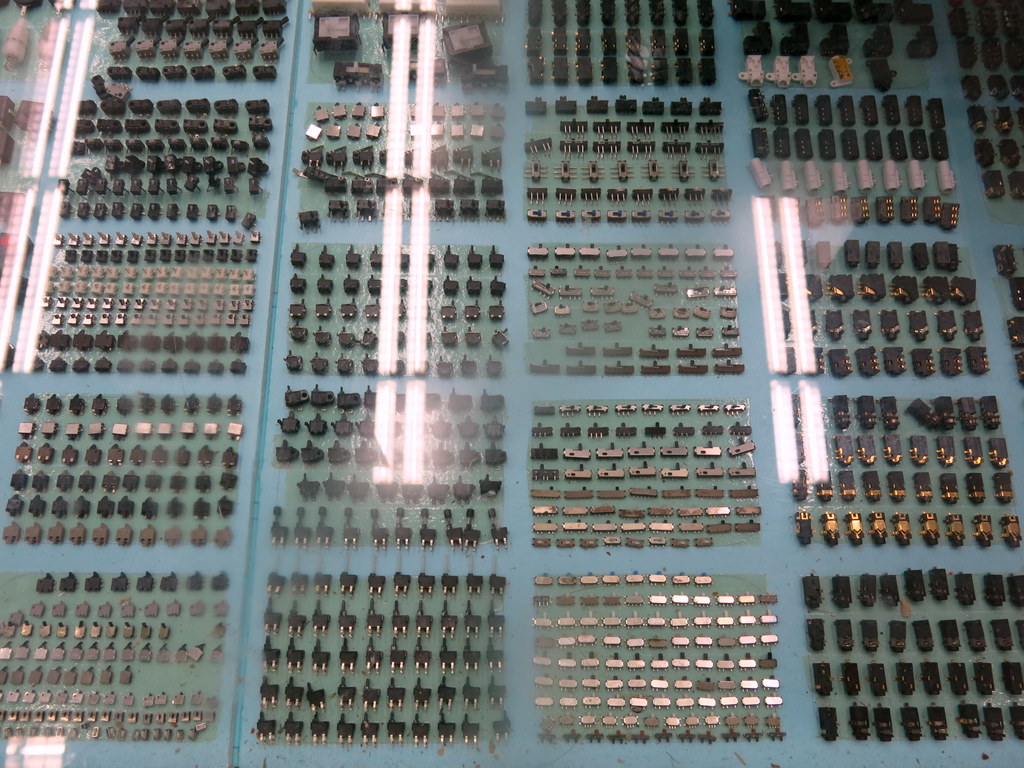
When I say ‘endless’, there is no exaggeration: standing at any point of the floor, you simply cannot see the end. It’s very easy to get disoriented. Also, there are multiple floors, each of which has a slightly different focus. The picture above on the right shows a counter that sells switches. Thinking of those times you spent on trying to find a Digikey part that fits your need? Here you can take out a real sample right at the counter and check it out in your hand.

I am curious how to choose which seller to buy from — since there are so many of them, the choice almost feels random. One thing I learned is that you shouldn’t feel rushed to buy: go around and compare different sellers before you make up your mind. Even at this low profit margin, there are still noticeable differences in price. Of course quality is also very important — often you can get a good idea by talking to the seller, and see if they are knowledgeable and professional. I tend to patron sellers who are willing to engage in a conversation and interested in knowing what I do.

It’s very easy to get lost and spend hours and hours here in the market. Moving to a different section in the building, I came across a floor which sells all sorts of cables, connectors, power adapters, terminal blocks etc. If you intend to buy a large enough quantity, you can also ask the seller to customize the product. Most things can be tailored to order. For example, I asked about 24VAC power transformers, and one seller told me depending on my need, they can customize the winding of the transformer and change the plug to any type of my choice. Wow, this is simply awesome 🙂 I was about to head to my next stop, which is the Sai Ge Electronics Market, and I ran out of time. So I will have to come back and visit again.

IMG_3203IMG_3202

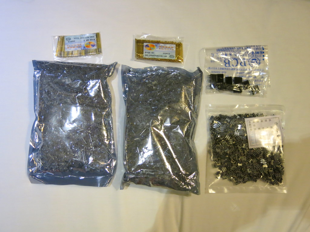
At the end of the day, I didn’t buy a whole lot: my goal was to do some initial sight-seeing in order to get an idea of where to focus my attention when I come back a couple of days later. Below is what I bought though: two bags of 1K self-flashing RGB leds, one bag of 1K SMD slide switches, two bags of 200 testing probes, and a few mini relays. With a total spending of less than $100, it’s a real bargain. Can’t complain at all 🙂

IMG_3204W091743357BDA7FCC

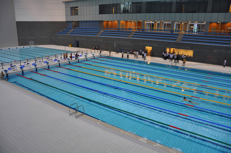
After I was done with HQB, my friend brought me to the swimming pool at the ShenZhen Bay Sports Center. This is undoubtedly the largest pool I’ve ever swimmed in, and a good way to end today. So long for today’s report. Will keep blogging tomorrow!

« Newer Posts - Older Posts »