Feed on
Posts
Comments

Hi, this is an alert to users who recently ordered OpenSprinkler Pi: we’ve found an annoying problem with the 8-pin ribbon / rainbow cable that comes with the package. Apparently many of the cables have disconnected crimp wires, causing the OSPi to not respond to RPi, or even worse, causing all stations to turn on at the same time. I estimated that there are potentially up to 60 orders that might be affected. We’ve proactively taken actions to send a replacement cable to everyone who ordered OSPi recently (within the last 2 weeks). If you are seeing an issue of your OSPi not responding to RPi, try to use a multimeter to measure the connection on each of the 8 wires of the cable. If any wire is not connected, please email to [email protected] and we will send you a replacement cable right away.

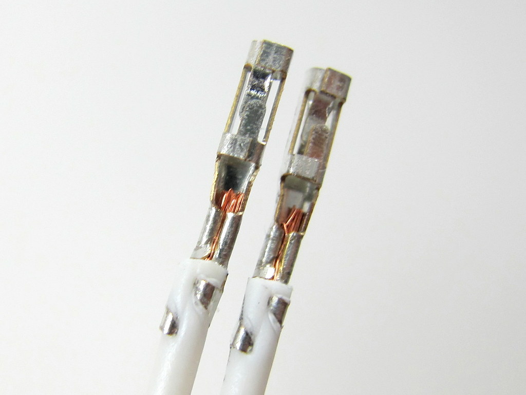
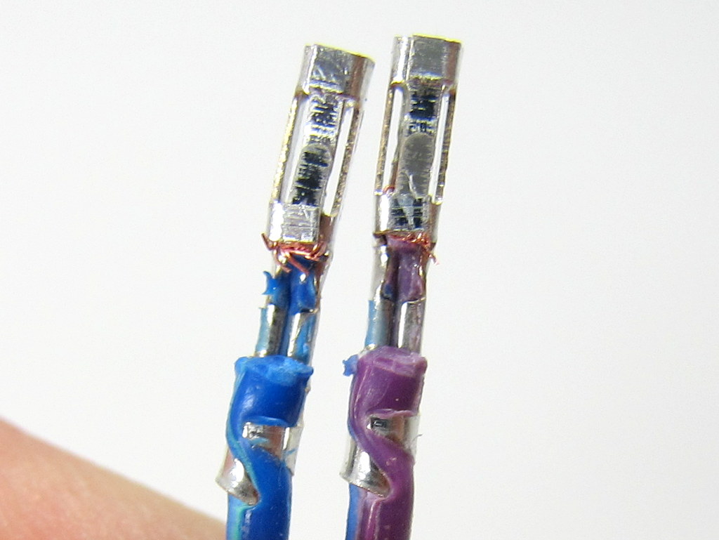
Here is a closer look at the cause of the problem. When I take the wire out of the crimp connector, you can clearly see that the good ones (shown on the left below) have metal wires tightly secured by the crimps, while the bad ones (shown on the right below) have the metal wires cut from the cable, resulting in disconnection. This is probably due to a defective wire stripper or crimp tool, or incorrect operation that causes the metal wires to be completely cut through. In any case, I’ve informed the supplier and complained about the the quality, and will never order from them again.

IMG_2963IMG_2965

So the lesson to learn here is that when testing OSPi, we really should use the individual cable that goes with each board, instead of using a common testing cable. Another lesson to learn is to never overlook any part, even something as simple as a cable!

I became aware of the cable issue when a couple of users reported that their OSPi did not work. This is very puzzling because every single board has been tested and verified, so the chance of DOA is very small. I’ve asked two of them to send their boards back to me, and after testing, I couldn’t find any obvious problem — the board works fine, and all demo programs work fine. However, until yesterday, I have apparently overlooked the problem with the cable: when testing, we have always used a common testing cable, instead of the user’s cable. Partly it’s because I never thought the cable would have any problem at all. Now I’ve learned a lesson, and it’s a good lesson to learn!

First off, my apology for not updating the blog for a while. Right after the Bay Area Maker Faire on May 18 and 19, I went to a trip to the UK for about ten days. Then as I came back, I was faced with a load of orders that need to be processed immediately. My friend Don and I spent three days non-stop shipping out packages. Now that all the back orders have been processed, I finally felt relieved and can come back to take care of the blog.

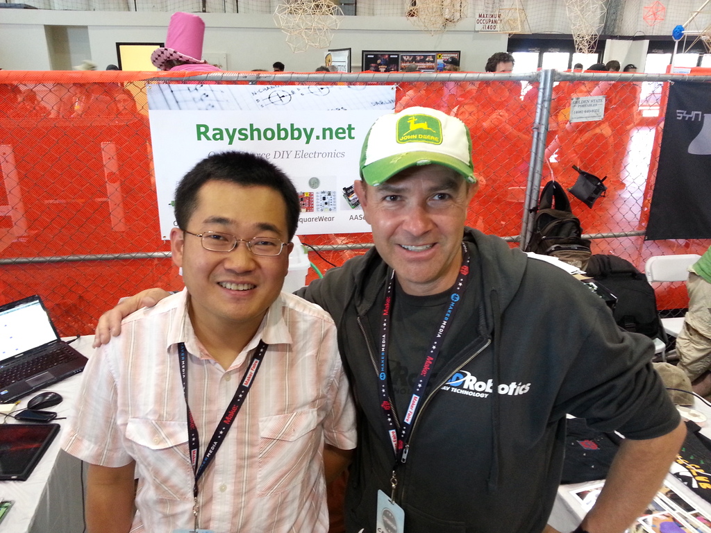
As a quick summary of the 2013 Maker Faire: we had a great show. A big thumb-up to Aaron Newcomb for helping me out. Without him, I would not have made it to the Maker Faire. Lots of people came by, chatted with us, provided valuable comments and suggestions, and expressed appreciation and love 🙂 I took pictures with Chris Anderson, and Eben Upton and Liz Upton. I also met and chatted with Laen from OSH Park, Ian Lesnet from Dangerous Prototypes, Mark Frauenfelder (Editor-in-Chief of the Make Magazine), Jason Babler (Creative Director of Maker Media), Michael Caster from the Maker Shed, and many others. This is such a fantastic event, and a great opportunity to meet and make connections with other makers.

20130518_12070120130519_151115

This year we didn’t bring many physical goods sell at the Maker Faire, but instead directed people to place orders online. This way we can devote more time to talk to people. Two interesting things I learned this year: First, AASaver is surprisingly popular and received much interest, but unfortunately I didn’t foresee this and hence did not prepare any new stock. What a pity! If I end up going to the New York Maker Faire later this year, I will make sure to take a batch of AASavers there. Second, kids really enjoy playing with flashing LEDs. We’ve set out a table with coin batteries and self-flashing LEDs, and provided simple instructions to make an LED throwie so people can make one right at the booth and take it away as a gift. This was hugely popular, and all the LEDs and batteries were consumed in no time. Apparently I should prepare more of these next time!

Of course the primary focus of the audience at our booth is on OpenSprinkler and OpenSprinkler Pi (OSPi). Since the release of OSPi just a couple of months ago, it has started gaining significant interest and has become the fastest growing product on my site. So far there have been more than 350 OpenSprinkler Pis out there in the wild. And as you can see from the forum, lots of people have been keenly working on developing their own software, using different programming languages and implementing advanced features such as weather-based control and sensor-based control. As I will talk about in the next post, the same firmware that’s running on the microcontroller-based OpenSprinkler has now been ported to OSPi, thanks to the generous contribution by Kimberling. So now you can run the same full-featured interval program on OSPi as in the standard OpenSprinkler.

But if you think the microcontroller-based OpenSprinkler is losing its charm, you couldn’t be more wrong 🙂 Although not growing as fast as OSPi, it’s still selling extremely well. Anyone who recently ordered the assembled OpenSprinkler has probably found out that we’ve been `secretly’ upgrading your order to a pre-release version of OpenSprinkler 2.0. As I will talk about in a follow-up post, OpenSprinkler 2.0 has an upgraded mcu (ATmega644), microSD card slot, the ability of adjusting LCD backlight brightness and contrast, more available pins to interface with external sensors and actuators, and pin headers to directly plug in an RF transmitter in order to interface with remote devices. The only difference of the pre-release version with the final version of 2.0 is in the enclosure design: the pre-release uses the current enclosure, and the final version (which is in production at SeeedStudio) will be using the new injection molded enclosure. There are many good reasons to prefer the microcontroller-based OpenSprinkler over OSPi: it is pre-flashed and works out of the box, so no hassle with installing raspbian, doing ssh, or dealing with Linux; it has LCD, buttons, and a number of analog pins to interface with external sensors; also I personally really like microcontrollers because of their simplicity and the fact that the controller is instant on when you need to restart it.

Uhh, I think my thoughts are already drifting away from the Maker Fairem which is supposed to be the focus of this post. So let me conclude this post here, and more exciting posts about recent updates will follow next!

Contrary to what I mentioned in a previous post, I have made the very last-minute decision to attend the Bay Area Maker Faire 2013. I will be flying out of Massachusetts early tomorrow morning, and get to the Maker Faire ground in the afternoon to do initial setup. Aaron Newcomb has kindly volunteered to help me at the booth. If you are planning to come to the Maker Faire, be sure to drop by our booth (exhibit 3375, Expo Hall with commercial makers), and watch our demos.

We will be showing most products I’ve developed so far: OpenSprinkler (including DIY 1.42u, the new assembled OpenSprinkler 2.0, and new injection molded enclosure), OpenSprinkler Pi, SquareWear (with lots of pictures of wearable electronics workshops I’ve hosted int he past, and SquareWear demos), AASaver (including the upcoming AASaver 2.0 I just blogged about earlier tonight). So it will be quite a show!

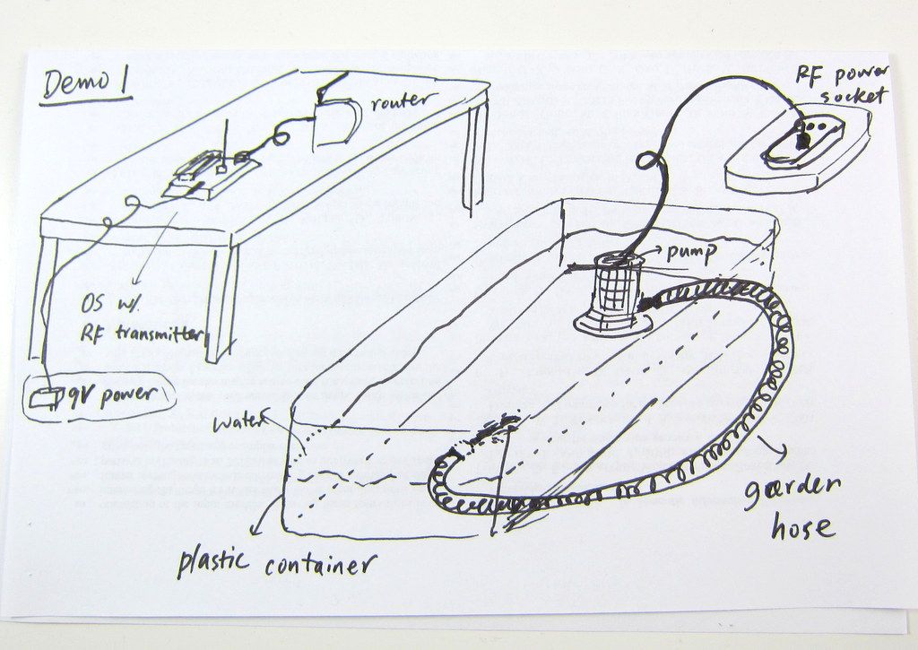
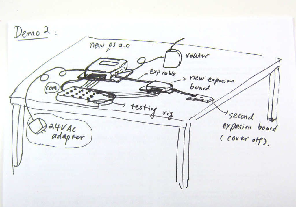
It has been fun to prepare the demos, and a lot of work too. Below are my sketches for two of the OpenSprinkler demos:
IMG_2713IMG_2714

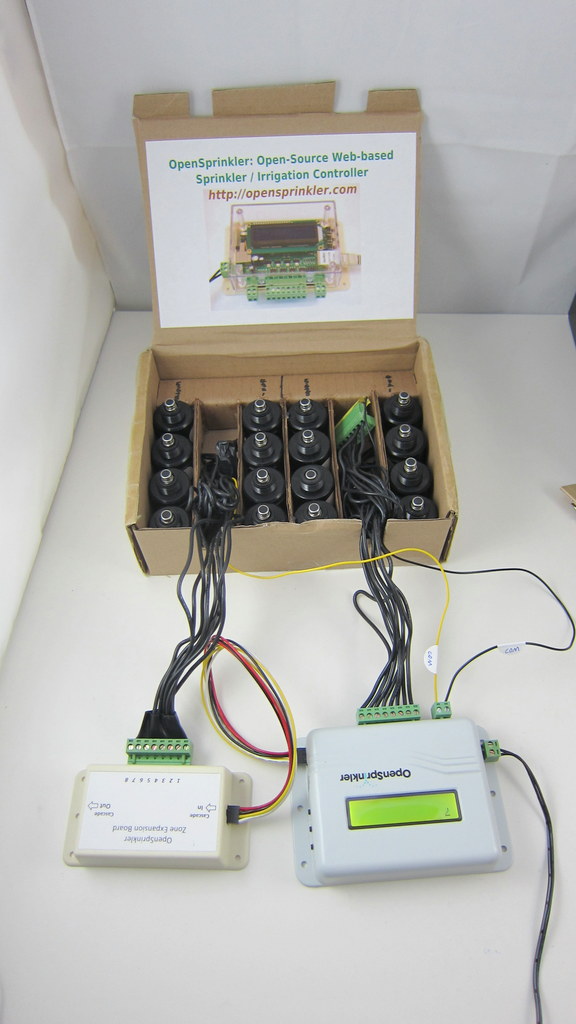
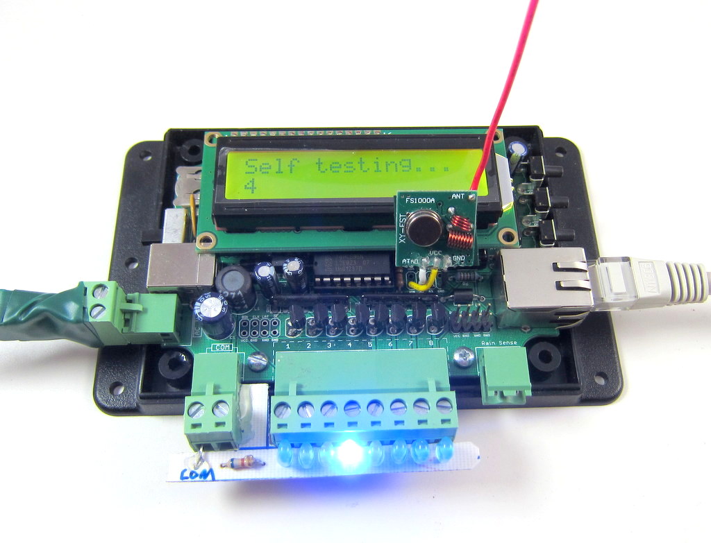
and some real gears to go with the two demos:

IMG_2715IMG_2712

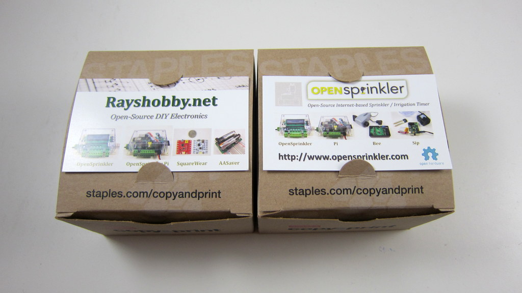
In terms of promotional materials, new this year I have made a banner and some business cards to be distributed at the table:
IMG_2718IMG_2719

These were made in the last minute, so they are not as professionally looking as I wanted, but the essential information is there 🙂 Also, I will have lots of colorful info pages and pictures at the table.

Time to go to sleep and prepare for the trip tomorrow. Hope to see you at the Maker Faire OpenSprinkler booth!

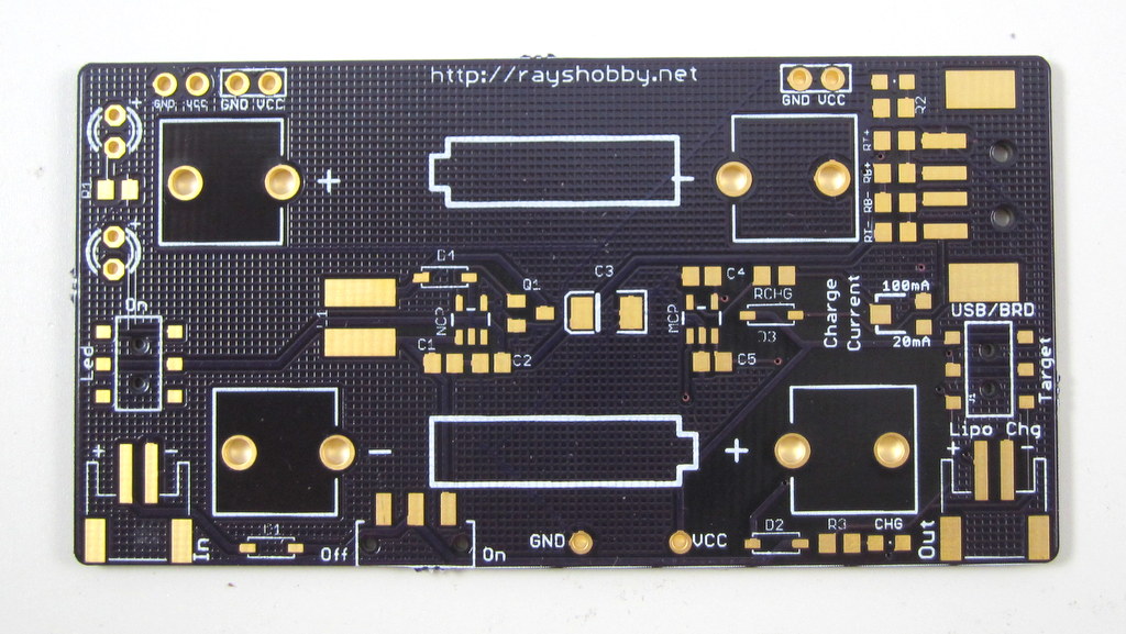
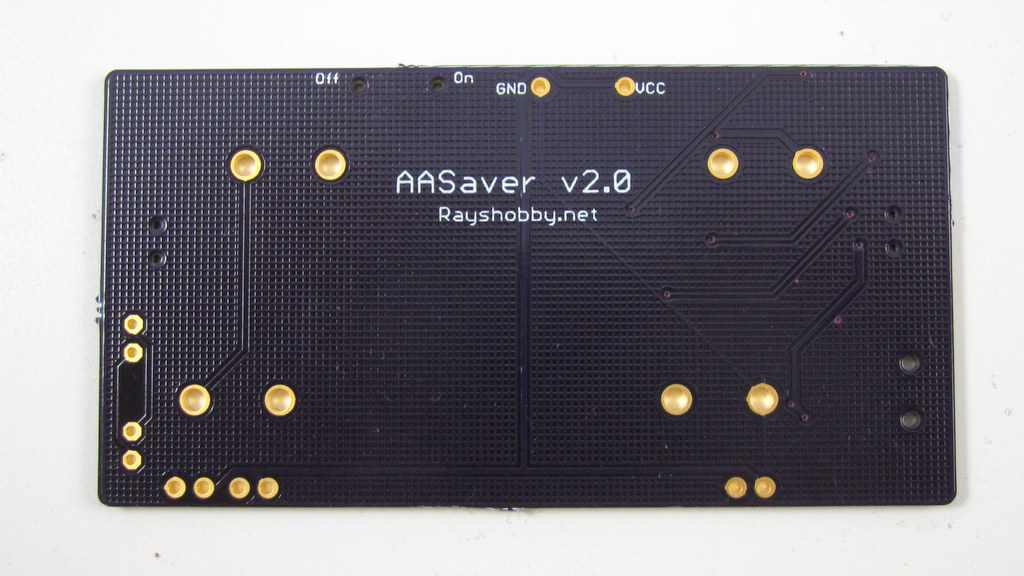
Yup, I opened my mail box and found the lovely purple envelope from OSHPark. What’s in it?
IMG_2720IMG_2721

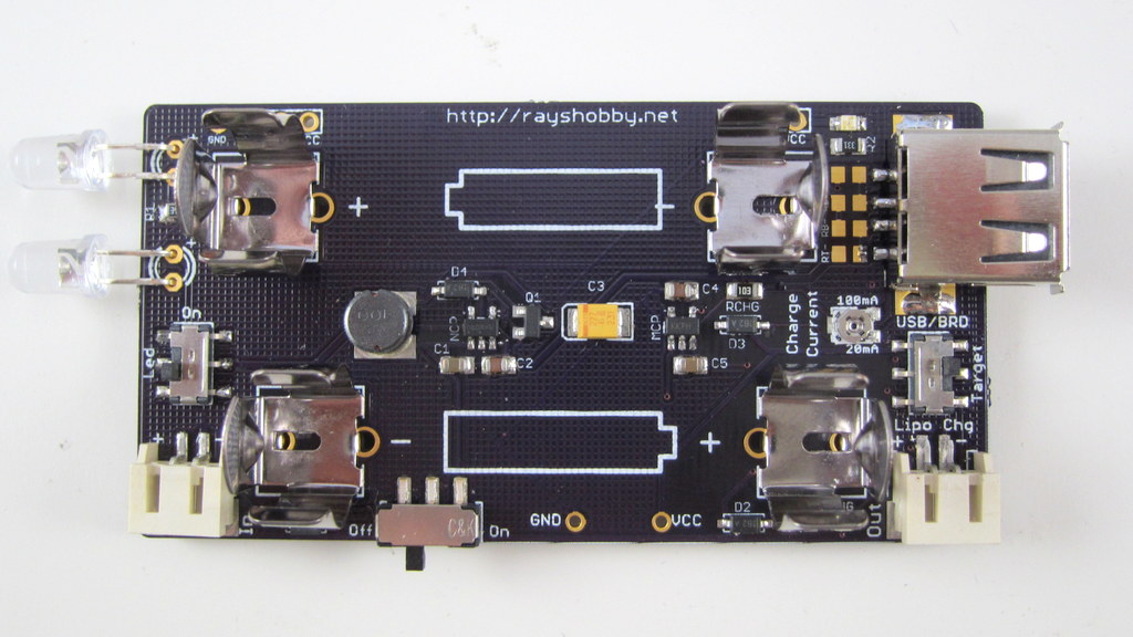
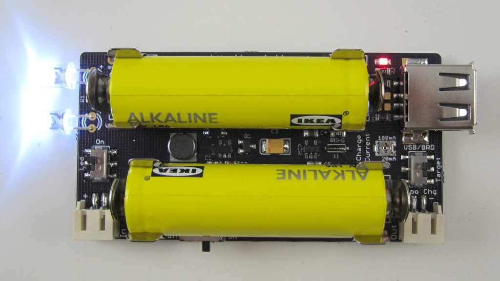
Ah ha, it’s the new AASaver 2.0 prototype PCB. I can’t help getting my hands on it, so I quickly assembled two. Here is what the assembled board looks like (without and with AA batteries):

IMG_2722IMG_2723

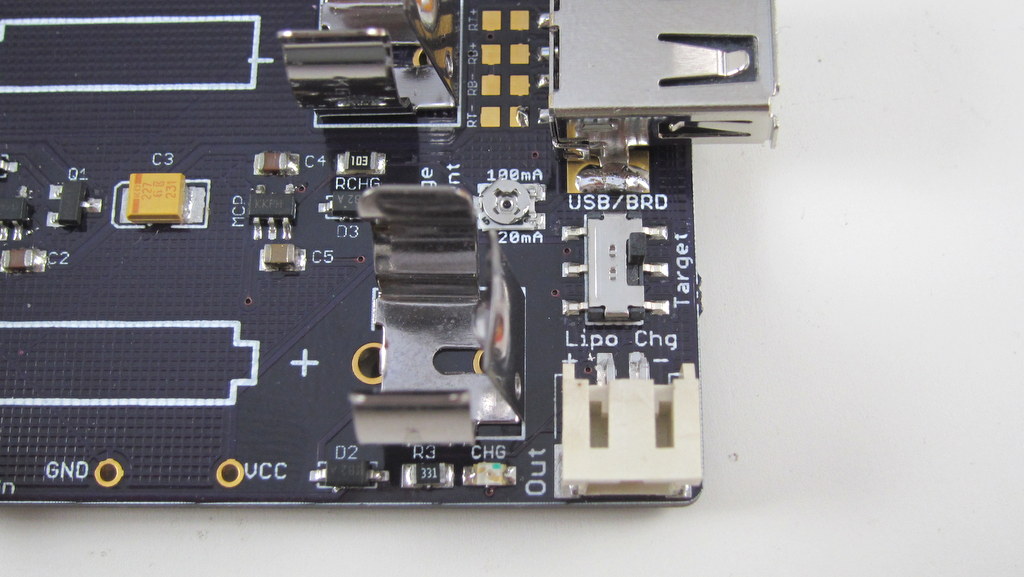
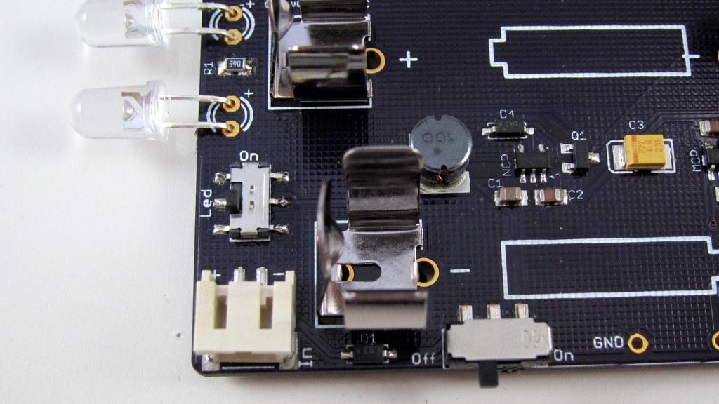
AASaver 2.0 is sort of a ‘mega’ version of AASaver 1.0: like 1.0, it takes two AA batteries and serves dual functions as both an LED flashlight and breadboard power supply. But it can do much more. First of all, I’ve added a LiPo charger circuitry so that you can use two AA batteries to charge an external LiPo battery:
IMG_2728IMG_2726

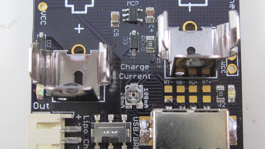
I’ve also added an SMT potentiometer (trimmer) to adjust the charge current (see the picture on the right above), anywhere from 20mA to 100mA. This is not a random addition — there is a good reason to have this feature, which you shall see in a minute.

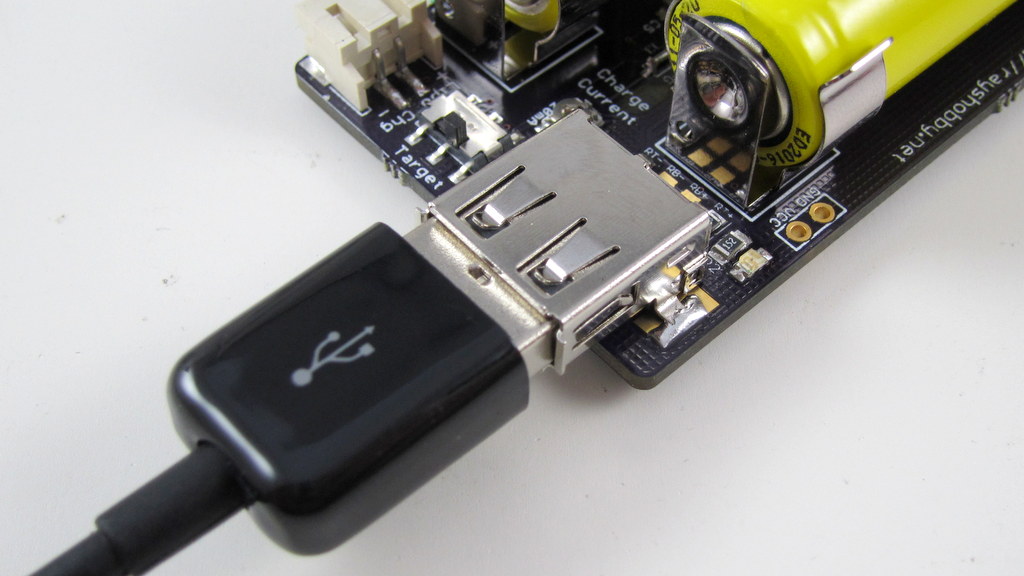
Another BIG addition is the functionality to charge USB devices like cell phones. Yup, you heard it right: there is a built-in type A USB receptacle that allows you to plug in a USB charging cable to add juice to your phone, MP3 player etc.

IMG_2725

So this is similar to Adafruit’s MintyBoost, except that there is a catch: on MintyBoost, you use a pair of fresh battery to charge the phone, but with AASaver the whole point is to harvest the remaining energy in used or old batteries. How does this affect anything? Well, used batteries typically cannot supply a high amount of current, so you can’t use them directly to charge the phone — it simply won’t provide enough current to charge. The trick is to dump the energy slowly into a LiPo battery, then charge the phone through the LiPo battery later! Essentially the LiPo battery serves as a ‘water bucket’, which accumulates charges slowly (like water drops), so that even used AA batteries can charge it; once the ‘water bucket’ has accumulated enough charges, it can dump the ‘water’ at much faster rate. This is the same idea as how solar chargers work: solar cells are too weak to charge phones directly, but you can build up the charges by leveraging a battery. Now you see why there is a built-in LiPo charger!

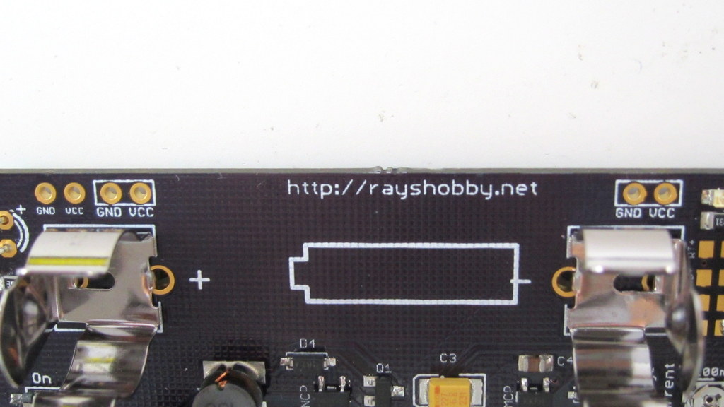
The picture below shows where the LiPo battery should be plugged in when you want to use it to charge USB devices. In sum, if you have a fresh pair of AA batteries, you can charge USB devices directly; otherwise you first charge the LiPo battery with a controllable charging current (20mA recommended), then use the LiPo to charge USB devices. The circuit of AASaver 2.0 accepts either AA or LiPo as the source of its boost converter, and directs the boosted 5V to either USB port, or LiPo charger, selectable through the ‘Target’ switch at the right-end of the board. On top of these, there is a separate switch for turning on the flashlight LEDs, and there are pin headers spaced appropriately to match a standard breadboard, so you can use it as a battery-based breadboard 5V power supply. As you can see, it has a load of new features to provide better and more flexible ways to save your AA batteries 🙂

IMG_2727IMG_2728

IMG_2727IMG_2724

I know, it has been a pain to compile OpenSprinkler 1.x source code, mainly because the firmware has grown to the point that you can only compile it successfully (i.e. within 32KB size) under a particular version of avr-gcc (4.5.3) in a particular version of Linux. This is very annoying for users who want to modify the source code and experiment with new features. That’s why I have decided to create a VirtualBox image with all the necessary software and settings that you need to easily compile it, without having to install a separate Linux system yourself.

Before you continue reading, please note that the VirtualBox Image is only useful if you are trying to modify the compile the source code yourself. To upload a pre-compiled firmware, you do not need any of these.

Wait, What?
VirtualBox is a free software that you can use to install and run a virtual operating system (OS) on your existing OS. Let’s say your computer runs Windows (i.e. the host OS). With VirtualBox, you can run a virtual OS (e.g. Linux) under the host OS, as if it is a Windows application but it’s a fully functional Linux system. This makes it easy to switch between different OS without having to restart your computer. VirtualBox is quite mature now. It makes use of hardware virtualization features available on most modern CPUs to provide fast speed. So even though you are running a virtual OS, it feels just as fast as a native OS.

One of the benefits of virtual OS is that the entire OS and all settings are stored in a single file — the VirtualBox Image — on your host system. So you can easily replicate the same virtual OS on different hosts by a simple copy-paste of the image file.

Download
To make it easy to compile OpenSprinkler code, I created a VirtualBox Image for Linux Mint 13 with all the necessary software installed. You can download the virtual image file from here:

Warning: the file size is 2.1GB, so it will take some time to download. Meanwhile, you can read the instructions below.
User and Password: the virtual OS has a default sudo user opensprinkler and the password is the same as the user name.
VMWare Users: check this forum post for instructions of converting VirtualBox image to VMWare image.
Unzip in Windows: do not use the built-in zip/unzip tool of Windows because it seems unable to recognize the correct file size. Use a third-party software such as 7-Zip or WinRAR.


Instructions
Step 1. Install VirtualBox

Download and install the latest version of VirtualBox from its official website. You should install the version corresponding to your host OS (Windows, Mac etc.). In the following I will use Windows as an example. After installing the software, you also need to install the VirtualBox Extension Pack. This is platform independent.

Step 2. Add a New Virtual OS
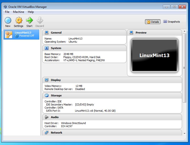
Unzip the file you downloaded to a local folder. I recommend creating a folder named VirtualBox VMs in your home directory, and unzip everything there. Next, run VirtualBox you just installed, and click on menu Machine -> Add. Navigate to the folder VirtualBox VMs \ LinuxMint13 and select the LinuxMint13.vbox file. Then click on Open to add the file. Now you should see an item named LinuxMint13 in the virtual OS list.

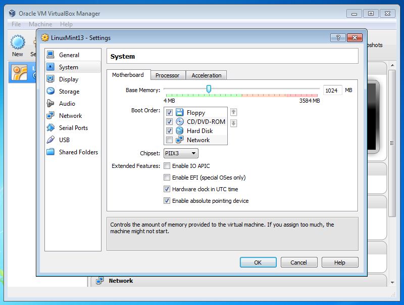
Click on Settings and make sure the default settings are compatible with your system. In particular, you should check if the Base Memory allocated to your virtual OS is not too large (it defaults to 2GB but depending on how much physical memory you have you may need to reduce it to 1GB).
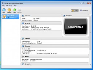
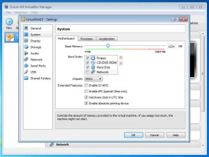
virtualbox_newvirtualbox_settings

Now you can click on Start to start the virtual OS. There will be a bunch of dialog boxes popping up with various information. If this is the first time you are using VirtualBox, you should read them thoroughly. Once the virtual OS boots up, you should see the desktop as shown in the following. If you want, you can press Ctrl-F to quit full screen mode, so the virtual OS will look like a normal Windows application running alongside with other applications.

virtualbox_desktop

Step 3. Compile OpenSprinkler Code
Arduino 0023 is pre-installed in the virtual OS. So you can just double click on the desktop icon to run it. Also, firmware 1.8.3 source code is pre-installed. So all you need to do to get started is to go to menu File -> Examples -> OpenSprinkler -> interval_program and then you can compile the code directly. If you need to change and file, or update to new firmware source code, everything is located in the arduino-0023/libraries/OpenSprinkler folder on the desktop.
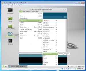
virtualbox_arduino

Note: the following two steps are revelent:

  • Specify your hardware version by opening file arduino-0023/libraries/OpenSprinkler/defines.h, and uncomment one of the lines #define SVC_HW_VERSION that corresponds to your hardware version. To identify your hardware version, check the version number printed at the top of your OpenSprinkler circuit board. The current version is 1.4.
  • If you own OpenSprinkler v1.0 or 1.1, you can no longer upload a program through FTDI. Instead, you need an external ISP programmer. An inexpensive USBtiny programmer is available at Rayshobby Shop.

Step 4. Upload Compiled Code
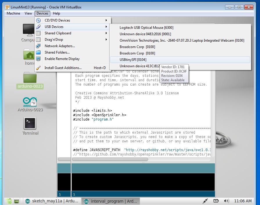
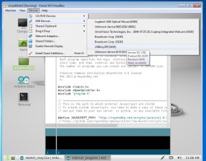
To upload the compiled code to your OpenSprinkler controller, first connect OpenSprinkler to your computer through the USB port. Then go to the VirtualBox software, and click (in the menu) Devices -> USB Devices -> USBtinySPI. This will allow the OpenSprinkler’s built-in USBtiny programmer to pass through directly to the virtual Linux and appear as a native device. Finally, click on the Upload button in Arduino and you are all set.
virtualbox_usbtiny

That’s all. Hope my effort is helpful for those who want to compile OpenSprinkler source code. Feel free to leave comments, and enjoy playing with the virtual Linux!
« Newer Posts - Older Posts »