Feed on
Posts
Comments

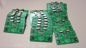
When you are making products in batches, you need a quick way to test them and make sure they function as expected. For example, three weeks ago, I sold close to 100 AASaver kits in a day, and I needed a good way to automate the testing before they are shipped out:

Well, this is what pogo pins are good for. So what is a pogo pin? It’s basically a spring-loaded pin that you can use to make a secure and temporary contact with your circuit board. It allows you to stack the testing circuit directly onto the target circuit, without any additional soldering. The picture on the right above shows an example I got from eBay. This is of model number P75-E, which is 1.02mm in diameter and 16.5mm in length, perfect for the AASaver circuit board.

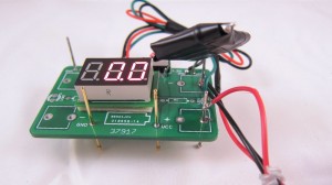
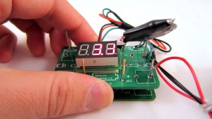
To build a tester, I need to: 1) provide input power to the target board; 2) test the output voltages (5V/3.3V); and 3) test the output current (>300mA). These can be done by making use of an existing AASaver PCB. I used a total of 5 pogo pins. Two are soldered into the battery holes to provide input power from two AA batteires; two are soldered into the Vcc and Gnd, and further connected to a mini voltage meter for testing output voltages; and one more to provide weight balance. See the pictures below.

To use the tester, I simply stack it onto a target board, and check the voltage readings. Each test can be done in less than 8-10 seconds. To test the output current, I added a 15 Ohm power resistor and a slide switch onto the testing circuit. When the switch is turned on, the power resistor is applied between Vcc and Gnd, which causes an output voltage to drop. This drop should be relatively small (<0.3V) if the target board meets the current rating (>300mA). So there you go: a simple tester for the AASaver!

AASaver Kit v1.1 is in stock

AASaver kit is now back in stock. There was a bit of delay in the shipping, but it has finally arrived! The funny thing is that the updated version (v1.1) arrived ahead of the original version, so if you place an order now, you will received the updated version, with additional features, at the same price!

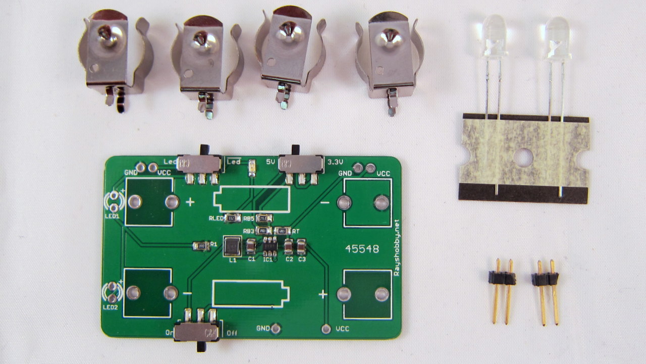
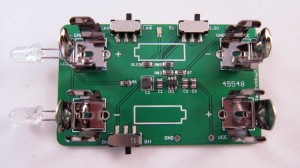
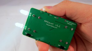
Picture of v1.1

Here is the list of changes in v1.1:

  • Moved both flash LEDs to the same side so they point to the same direction.
  • Added an on-board resistor (R1) for the flash LEDs.
  • Added a separate flash LED switch.
  • Moved the power switch to the bottom side.

These changes were made to improve the usability. For example, the separate LED switch allows you to use it simultaneously as a breadboard power supply and flashlight (previously it was either one or the other). Also, the two LEDs now point to the same direction, so it can function better as flashlights.

The kit is available in my hobby shop. As I said, if you place an order now, you will get the updated v1.1 at the same price, until it runs out.

The AASaver kit is now out of stock. In one day I’ve received about 92 orders, pretty crazy 🙂 I’ve placed another order of PCBs, and expect to have the kit back in stock in about three weeks. You can sign up to receive email notifications here: http://eepurl.com/jBK15, or alternatively, subscribe to my blog RSS Feed.

What is AASaver? Well, simply speaking, it’s a small voltage booster that can bump the voltages on your AA batteries to 5V or 3.3V, which you can use to power flashlight LEDs or breadboard circuits. It has some nice features, including on-board flashlight LEDs, voltage selection switch, power switch, and breadboard pin headers. I like it and I find it really useful. It is available for purchase in my online shop. Check out the full product details and a video demo on the product page:

http://rayshobby.net/aasaver

AASaver just got posted on Hack A Day yesterday afternoon. Thanks for the publicity (Hack A Day is awesome!), orders are pouring in! The version without LEDs is already out of stock. I have placed a batch of orders and it should be back in stock in about 3 weeks. If you want to get notified when it’s back in stock, sign up for the AASaver stock notification list, or simply sign up for my blog RSS feed.

Rain/freeze sensors are useful for detecting rain or freeze conditions, and delays or stops watering accordingly. There are many types of rain sensors on the market. Recently I tried out this Orbit 57069 rain/freeze sensor. It’s very easy to connect to OpenSprinkler, and works quite well. The rain delay time can be easily adjusted by setting the water evaporation speed.

So how does this rain sensor work? It’s pretty simple. The sensor has two wires, which are normally connected to each other inside through a switch. The top of the sensor has a small chamber, which contains a string of sponge pads (see below). When it rains, the water will drip into the chamber and gets absorbed by the sponge pads. The pads will then expand and press against each other as well as the top of the chamber. When it expands to a certain point, the switch inside the sensor will be pressed down, disconnecting the two wires. The height of the chamber can be adjusted to control when the sensor is activated – in other words, the amount of rain that will activate the sensor. There are five options: 1/8, 1/4, 1/2, 3/4, and 1 inch.

Down below the chamber is an evaporation window. The size of the window controls how fast the absorbed water evaporates, thereby controlling the rain delay time. After the rain stops, the sponge pads will gradually shrink, and at some point the switch is released, thus the two wires are connected again. This is a very clever design because it’s purely mechanical, requires no power itself, and is easy to adjust. The downside is that you cannot set the delay time precisely – obviously the local humidity and temperature will affect the evaporation speed.

Once you figure out how it works, it’s very easy to connect it to OpenSprinkler. The diagram above shows the connection (Not sure where the ‘common wire’ is? Check out this diagram). Simply put, the sensor acts as a normally-closed switch placed on the common wire. When the sensor detects rain or freezing condition, it disconnects the common wire from the sprinkler valves. As is, it can work with almost any kind of sprinkler timer, without modifying the timer itself.

The sensor should be installed on the roof or next to the gutter. You need to run a wire from the sensor to your sprinkler timer. The sensor itself comes with a relatively long wire, so that shouldn’t be a problem. If you want, you can even get a wireless version at a slightly higher cost.

That’s it – if you need automatic rain delay control, this is an easy, inexpensive option you may consider.

« Newer Posts - Older Posts »