Feed on
Posts
Comments

24VAC to 5VDC Conversion

Voltage conversion from 24VAC to 5VDC is quite useful, because a lot of home automation devices use 24VAC, including sprinkler solenoids, home surveillance systems etc. Having a conversion module makes it easy to use a single power supply, without a separate 5V adapter for your control circuit. There are plenty of resources you can find online about it. But these resources are rather scattered. So in this blog post I will summarize and discuss the common choices.


AC to DC Rectification

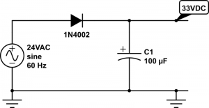
Before we begin, the first step is to have a rectifier that converts voltage from AC to DC. The common choices are half-wave rectifier (which requires just one diode) or full-wave rectifier (which requires four diodes). For simplicity, I will use half-wave rectifier as an example. The typical schematic of a half-wave rectifier is as follows:

half-wave-rectifier

It’s simply a diode followed by a capacitor to smooth out the rectified AC waves. As we know, diode only allows current to flow in one direction, so after the AC voltage passes through the diode, only positive voltage remains. The diode must be selected based on the maximum reverse voltage and the maximum current. One thing easy to forget is that when we talk about 24VAC, we mean the RMS (root-mean squared) magnitude of the voltage is 24V. Since AC voltage is a sine wave, the peak voltage is actually 24 * sqrt(2) = 34V, which is quite a bit higher. The maximum reverse voltage applied on the diode is therefore 34 – (-34) = 68V, which is when the AC voltage runs to the negative peak. So a diode with 70V peak reverse voltage is sufficient.

In practice, transformers that are rated 24VAC usually have a higher no-load voltage, which can vary between 26VAC up to 28VAC. This is typical, and the voltage is supposed to drop close to 24VAC under maximum load (i.e. the current rating of the transformer). As a result, when the circuit is powered on, the transformer can output a peak instantaneous voltage of up to 28 * sqrt(2) = 39.6V.

In the schematic above, I’ve picked a 1N4002 diode (70V reverse voltage, 1A current) and a 100uF/50V capacitor. These should work well for common scenarios. Note that the voltage output on the capacitor is approximately 34V – 1V (diode’s forward drop voltage) = 33VDC. Again, when the transformer is well below maximum load, the output voltage can go as high as 39.6V – 1V = 38.6V.

So next time if you see a power transformer rated 24VAC, after rectification, gives 39VDC, don’t be surprised!!


Now that we have a DC voltage, the next part is to step it down to 5VDC. We want it to be regulated, so that the voltage won’t fluctuate much. There are a variety of solutions:

1. Zener Diode

Probably the simplest solution is to use a Zener diode. As we know, a Zener diode can force the voltage across it to remain constant (break-down voltage) when it’s in the break-down condition. This condition is met when the current flowing through it (in reverse direction) is at least a few milli-amps (5mA typical) but less than the maximum current allowed (e.g. the diode’s power rating divided by its break-down voltage). For example, a 5V/1W Zener will remain in break-down condition when the reverse current is between 5mA and 1W/5V = 200mA. The typical schematic is shown as follows:

zener_regulator

Here resistor R1 is used for current limiting. Assume D2 is a 5V Zener diode, and the circuit on the right-hand side draws about 180mA current. R1 must be selected such that the current flowing through it is 180mA plus at least 5mA to keep D2 in break-down condition. So we have R1 = (33 – 5) / 0.185 = 150 ohm. Note that D2 should be rated at least 1W, because in case of open-circuit, it needs to absorb the entire 185mA without burning out.

Now let’s take a look at the power rating of the resistor R1. Since the current flowing through it is 185mA, the power is 0.185 A * 0.185 A * 150 ohm = 5.1 Watt. Wholly crap — this is gotta be a big resistor, isn’t it :). Well, this is the unfortunate drawback of a Zener diode based regulator, that is, it can waste a lot of power and require a bulky resistor. Fundamentally, it regulates the voltage by converting the voltage differential to heat. In this case, the voltage differential is quite big (33V vs. 5V), and the current draw is fairly large (180mA) too, so it ends up wasting a lot of power in heat.

Another drawback is that to increase the current draw, we must decrease R1. Otherwise, if the output circuit starts to draw, say 250mA, that will take D2 out of its break-down condition, and the output voltage is not regulated any more. So overall it is only suitable if the current draw is constant and small (e.g. tens of milliamps).


2. Linear Regulator

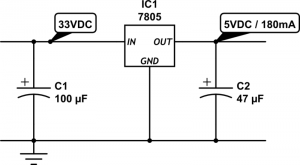
Another simple solution is to use a linear regulator, such as the popular 7805. The typical schematic is as follows:

linear_regulator

The circuit is quite simple, and the output current can vary across a wider range. However, linear regulator shares the same drawback with Zener diodes, that is, it fundamentally works by converting voltage differential to heat. As a result, it wastes the same amount of energy (5.1 Watt in this case) in heat. This is not only a matter of waste, but also it requires a large heat sink to dissipate the heat, otherwise the regulator will burn and smoke. So clearly not an efficient solution. In fact, the efficiency of a linear regulator is the ratio between the output and input voltages. In this case, it is 5 / 33 = 15.15%, which is very poor.


3. Switching Regulator

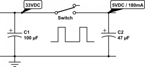
Now we have come to my favorite topic: switching regulator, also known as switching converter, or switch-mode power supply (SMPS). It uses transistors and a reactive component, namely inductor, to convert voltages much more efficiently. Ideally the switching converter works by simulating the following:

smps_ideal

That is, imagine there is an automated switch between the input and output. When the switch is turned on, it connects the input to output, and when it turns off, the input and output are disconnected. This essentially generates a square wave with 33V peak voltage, and the duty cycle is determined by the switch. Suppose the duty cycle is 15.15%, as long as the switching frequency is sufficiently high, at the output it would seem as if you have a constant voltage of 33 * 15.15% = 5V. That’s it, simple!

The main advantage of switching regulator is that since there is no resistive element, theoretically there is no energy loss at all, so the conversion efficiency is 100%! Of course in practice there will be some energy loss due to the imperfections of electronic components. Still, even at 75% efficiency, we are talking about a power waste of only (5V * 0.18A / 0.75) – (5V * 0.18A) = 0.3 Watt, much better than the 5.1 Watt waste you saw previously with a linear regulator.

The schematic above may look very simple. But it doesn’t tell the whole story. Implementing the switch is more complicated than you might think. That brings out the drawback of a switching regulator, namely cost and circuit complexity. It typically involves a transistor or MOSFET that functions as a digitally controlled switch, an oscillator circuit that generates a control square wave, a voltage reference and feedback module that monitors the output voltage, and finally a current sensing or thermal shutdown module that protects the regulator. That’s why switching regulators are typically provided as integrated circuits.

MC34063
Probably the cheapest and most widely used switching regulator is MC34063. The volume pricing (quantity 100+) is only 20 to 30 cents. Dave Jones at the EEVblog has a nice video tutorial about how to use MC34063. Also, there are a lot of MC34063 calculators you can find online, which will help you figure out the component values and parameters.

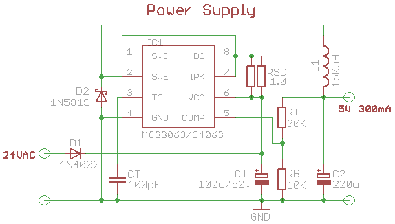
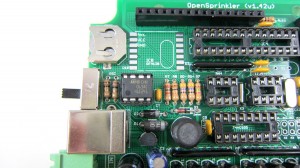
The schematic on the left below shows what I have been using for OpenSprinkler. MC34063 has a maximum input voltage of 40V (and some manufacturers make it 45V), so it’s perfect for our purpose. The main peripheral elements include inductor L1 (150uH), Schottky diode D2 (1N5819), timing capacitor CT (which controls the switching frequency), current limiting resistors Rsc (0.5 ohm), and feedback resistors RT and RB. This circuit can provide 5V 300mA output. The image on the right below shows a picture of the switching regulator section on OpenSprinkler 1.42u DIY kit.
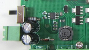
mc34063_schIMG_2627

IMG_2666On OpenSprinkler Pi, Rsc is reduced to 0.33 ohm (three 1 ohm resistors in parallel) in order to provide higher current required by RPi. The picture on the left shows the switching regulator section on OpenSprinkler Pi, which uses all surface mount components.

MC34063 is quite flexible. It’s not only useful for step-down voltage conversion, but it can also do step-up conversion (i.e. the output voltage is higher than input voltage), and voltage inversion. On the other hand, it requires a number of peripheral components, and picking the right component values can be tricky, especially if the output current can vary across a wide range. It’s also prone to noise (remember those annoying humming noise from cheap power adapters), and its maximum current is limited to 1.5A.

Overall if you want a cheap switching regulator, and your circuit draws roughly a fixed amount of current well below 1.5A, then MC34063 is a great choice to consider.

LM2596
More recently I’ve started using LM2596 as a replacement for MC43063. I came across it when I was shopping for a modular step-down converter and noticed this one from Amazon.com. LM2596 provides up to 3A output current, requires only a small number of peripheral components, and is more reliable and less noisy. In fact, when I started working on OpenSprinkler, I have used a similar product LM2574 for a while, but that has a current limit ot 500mA, and the switching frequency is much lower.

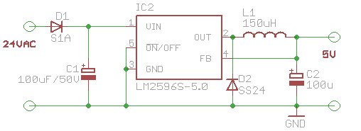
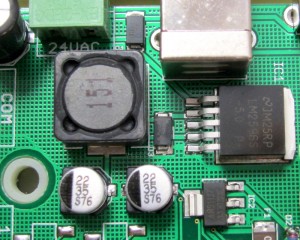
Here is the new design of the voltage conversion section in the upcoming OpenSprinkler 2.0 and OpenSprinkler Pi 1.1:

lm2596_schIMG_2709

It uses LM2596-5.0, which has a fixed output voltage of 5.0V. The number of peripheral elements is minimal, and the circuit design is very clean. The main downside is that it is considerably more expensive than MC34063. So the extra capabilities don’t come for free 🙂 Still, for reliability and clean design, I have decided to adopt it for all future circuits.


4. Other Solutions

The above has summarized the common choices I’ve learned through my experience. There are certainly other solutions as well. For example, you can use a transformer to step 24VAC down to 5VAC, then from that point on you can use a rectifier followed by a linear regulator to convert it further to 5VDC. This is fairly efficient because transformers can have high efficiency, and the linear regulator in this case is also efficient because the voltage differential is small. However, transformers are bulky and expensive. and this solution is not suitable if the input voltage varies across a wide range.

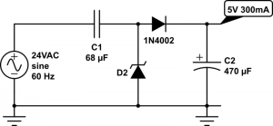
Another choice is to use a capacitor for current limiting, in conjunction with a rectifier and a 5.6V Zener diode for voltage regulation. The idea is similar to solution 1 above, except it uses the capacitor’s reactance (instead of resistor’s resistance) to limit current. Since there is little energy loss, this is very efficient and is similar to the transformerless power supply design, which is frequently found in small wall adapters. Unfortunately, to provide sufficiently high output current (more than tens of milliamps), you will a capacitor that has high capacitance (e.g. 100uF) and is non-polarized. This is not easy to find in real life.

transformerless_sch

Finally, you may be wondering why not use a resistor-based voltage divider to split 5VDC out of the 33V rectified input? Well, this is a terrible idea in almost any circumstance I can think of. The reason is that the output voltage will fluctuate considerably depending on the current draw. In other words, it is not regulated. So I can’t think of any real use of it other than providing voltage reference.

That’s all. I hope this blog post provides useful information for your own power supply design.

46 Responses to “24VAC to 5VDC Conversion”

  1. Nico says:

    You really should rethink the layout of your LM2596 design.

    1.) The Inductor should be closer to the IC.
    2.) Where is the output capacitor? It needs to be close to the Inductor, otherwise your feedback will be anything but valid.
    3.) Where is your input capacitor? While it’s on the schematics, it seems to be missing on the PCB.
    4.) Don’t use a hatched ground-“plane” … just don’t 😉 It’s a relique from the old days.

    I’m sorry, but this power supply looks like a real EMI-disaster waiting to happen. And the whole regulation will not be very reliable.

    • ray says:

      Thanks for the suggestions. The input and output capacitors are on the lower left corner, which I cropped out from the image. I know that the inductor and capacitors should be placed close to the IC, but their positions are restricted by other factors. In particular, since there is an RPi sitting on top of the board, and these components are quite tall, they have to be placed on the boundary. As you can see from this image:
      http://rayshobby.net/wordpress/wp-content/uploads/2013/04/IMG_2669_a.jpg
      the space on the boundary is very limited, so they have to remain where they are. Also note that I am using a shielded inductor and a fixed voltage LM2596, which has built-in feedback resistors.

      Regarding the hatched ground plane, I am mainly using it for better thermal and mechanical properties. It might not be necessary, but I haven’t heard that it hurts anything.

      • Nico says:

        This is a tradeoff you should not do on an SMPS.

        Here is a little article which goes into more detail on this: http://www.electronicproducts.com/Power_Products/Power_Management/Avoiding_common_errors_when_designing_an_SMPS.aspx

        The “Layout” section shows why you should keep the capacitors as close as possible.

        This SE entry also explains some of the concepts very nicely:
        http://electronics.stackexchange.com/questions/17993/smps-pcb-design-critic

        If you’re constrained by mechanical obstacles you might consider using other components, like smaller (in regards to the height) capacitors or even ceramic capacitors. While the last ones might be a bit more expensive, they provide VERY good properties for SMPSs.

        The shielded inductor helps you to mitigate the directly emitted RF from the inductor, but you’ll still emit a LOT over the the rather long traces between the input capacitor over the internal switch of the LM2596 and to the inductor. As the traces also act as small inductors you’re building something similar to a filter which is going to affect your VIn and emits RF. Remember, the input is a square-wave so the most important portion of the signal (RF-wise) is the rise/fall time, which can be very high frequency.

        It will also be bad on the output-trace between the inductor and the capacitor.

        The internal feedback resistors also do not help in any way. The problem is that you take the feedback-signal far away from your output capacitor. There will be a lot of (sawtooth like) ripple on that signal, which is going to affect the regulators feedback loop maybe even driving it into oscillation.

        Try to get your hands on a scope and look at VIn and FB. You might also just hold the probe over the board to see some spurious emissions.

        Remember that all the emissions will be fired directly into your RPi, which might lead to VERY strange problems.

    • ray says:

      Fair enough. I’ve updated the picture which shows the regulator section on a different board. The components are placed fairly close to each other.

      By the way, I’ve checked the recommended layout from the datasheet:
      http://www.onsemi.com/pub_link/Collateral/LM2596-D.PDF
      and I don’t think the components are placed extremely close to each other. Well, I guess what counts as close or not close is somewhat subjective.

      • Nico says:

        Yes, this one looks better, but still it should have an input capacitor closer to the lm2596, adding a small (1µF or so) ceramic capacitor close to the IC might already help a lot. Also, you should try to make the traces wider to reduce their inductance.

        The OnSemi example is okay-ish. The capacitors are close to the in- and outputs. And the traces are wide. But IMHO it could have been done a better than this. You have to keep in mind that the lm2596 is quite old (at least 15 years, probably close to 20). These days the reference layout would look quite different, most probably not even using any THT components anymore.

        The general rule of thumb in SMPS-design is “keep the in- and output current loops as small as possible”

  2. Mark says:

    There is a better data sheet for the LM2596 with a PCB layout included at the TI site.
    http://www.ti.com/lit/ds/symlink/lm2596.pdf

  3. Lisandro says:

    Hi, I’m trying to use the LM2596 converter to charge two cell phones (Motorola phone, Samsung smartphone). I bought one of those modules, wired a microUSB connector to the output, and there’s enough voltage, but the smartphone refuses to take charge. Am I missing something? Do I have to add something extra to the data cables on the microUSB connector?

    • ray says:

      Not sure. The only thing I know is that iPhone uses the data pins (D+/D-) to indicate charging current. If no voltage is presents on D+/D-, the device may refuse to charge. I haven’t heard of a similar thing for Motorola or Samsung phones. For details about iPhone, you can refer to Adafruit’s MintyBoost.

  4. Jeff says:

    Ray, thank you for this excellent article. It discussed all the early alternatives I was considering, and pointed out the flaws I was worried about. You gave some efficient solutions that will save me a ton of time. I want to take the 24VAC from my thermostat to power my Raspberry Pi. I think these will help me tremendously.

    Thanks.
    Jeff

  5. Patricio says:

    Hello, thenk you very much for this information. I would like to ask you about the last circuit in the point “4. Other Solutions”, the 69uf capacitor, what kind has to be them ? Metallized Film Capacitor ? thank you very much for your answer

    • ray says:

      it has to be a non-polarized capacitor, such as ceramic, mica, because it needs to allow AC to pass through. Non-polarized capacitors usually don’t have high capacitance, 69uF is already quite large. this solution is really only suitable for small output current.

  6. Z says:

    According to Wikipedia, the DC voltage of a half wave rectifier is Vpeak/Pi, http://en.wikipedia.org/wiki/Rectifier

    • ray says:

      That is assuming there is no storage element like capacitor (i.e. the half-wave is directly followed by resistive load). This is not the case with most power supply designs, as there is always a big capacitor to smooth out the voltage variations. As a result, unless if the load is drawing a large amount of current, the smoothed out voltage is close to the peak voltage.

  7. Dan says:

    Am I missing something?

    Why is there not a full bridge wave rectifier and a decent capacitor in front of the LM2596?

    While a few pennies more, isn’t it better to pre-filter the incoming DC voltage?

    If I’m wrong, please share your knowledge.

    padapa

    • ray says:

      Please check the schematic: it’s a half-wave rectifier and there is a 100uF capacitor. Of course you can upgrade the capacitor to a bigger one but 100uF is sufficient. The reason to use half-wave rectifier is that the solenoid driver must share a common ground with the 24VAC input. Full-wave rectifier cannot allow this.

  8. Martin says:

    Hi Ray,

    many thanks for this article – very interesting read. I am sure I’m missing something, but when I look at the data sheet for the LM2596, Table 1 suggests a 47uH inductor for 5V output. In your schematic there’s a a 150uH inductor. I’m sure you have a reason for this, but at this point I don’t see it. A brief explanation would be great.
    Many thanks!

    • ray says:

      Yes, there is a reason: the OpenSprinkler circuit is designed to supply 1 amp maximum current on the 5V line. If you check the datasheet of LM2596, at 1 amp maximum current, you can use an inductor in 100 to 150uH range. It won’t hurt if you use a 47uH one (which means it’s capable to output 3 amp maximum), but for me since the circuit is never supposed to output more than 1 amp, I decided to go with 150uH.

  9. Martin says:

    Thanks for the reply, Ray. Makes perfect sense, don’t know why I didn’t see that.

  10. David says:

    Hi Ray,
    Would you be able to make these 24VAC to 5VDC @ 1 to 1.5 amp output to power the Rasp Pi and sell in your store?

  11. Chris Sparks says:

    I really loved this article. I really need to get smarter with electronics so I can understand it. Being a software engineer didn’t get much electrical engineering. Anyway. What caught my eye was not having enough amperage to support the PI with a 24V line, like from an HVAC system. I wanted to make a Pi thermostat because I wanted to be able to control my HVAC system via programming of my own. I need to device a setup so that I can control the activation of both units in unison. I didn’t want both compressors turning on at the same time to avoid high demand charges.

    • ray says:

      If the 24VAC transformer is not powerful enough, you should consider powering Pi separately with its own USB adapter.

      • Chris Sparks says:

        Well that is my issue since I’d have to run wire in the wall to a power source since I don’t want to have the power cord hanging from the wall.

      • ray says:

        Actually drawing power from 24VAC has been a design challenge for many WiFi based thermostats like Nest. They generally require what’s called the ‘C’ wire (common wire). Older systems don’t provide a C wire, as a result, you will need to have a rechargeable battery and use the so called ‘power stealing’ technique to power the thermostat.

      • Chris Sparks says:

        I had given the rechargable battery idea a thought but I don’t know where to find such a device to wicker into my project.

      • Jon says:

        Would using a full-wave rectifier for the input rather than half-wave make a difference in the power available since it would be pulling from the whole wave instead of just one peak?

        Like Chris I am looking at a Pi for a thermostat and I’m using the touchscreen, and the draw is between 4.5W and 7.5W. I’m designing a circuit board right now and I’m waffling on half-wave vs full-wave. Though I’m trying to keep size down so it isn’t the monetary cost of 3 extra diodes (I could not care less about that), but the physical space required by them.

      • ray says:

        Full-wave is more efficient in terms of using the full cycles of AC, but it’s not like half-wave wastes more energy — it just doesn’t utilize the negative half cycles of the AC (and not utilizing it does not mean it’s wasted since it doesn’t draw any current from the negative half cycles).

        The main reason that for OpenSprinkler design I have to use half-wave is that the triac needs to share a common ground with one of the AC wires, due to the way triac (and generally transistors) work. There is no clear way how to use full-wave rectification in this case because it doesn’t allow sharing the circuit ground with one of the AC wires.

  12. Chris sparks says:

    I am lucky in that i have that common wire. I called an hvac friend of mine and he says that the transformer for the thermostat is 20VA so at 24 volts that’s about 1.5 amps.

  13. José says:

    I am doing a project for controlling 24VAC sprinkler valves from orbit, and i have built the rectifier and I’m using an LM2596 to power an Arduino and an XBee. I will be using the same 24VAC to power the solenoids. Should I be worried about the solenoids interfering with the Arduino? I should mention that I will be using SSRs to control the valves.

    • ray says:

      It should be fine. The LM2596 regulator will stabilize the voltage for Arduino and XBee so that the solenoids won’t interfere with them.

  14. Jeff says:

    Ray,
    Thanks for the article. I think an LM2596 is in my near future.
    I have a question about the rectifier diode reverse voltage. Early in your article you say the peak reverse voltage from a 24VAC source can reach 68V, hence the IN4002. But in you LM2596 design you use an S1A which is a 50V device (far as I can determine.)
    Am I reading the S1A spec wrong?
    Much obliged,
    Jeff

    • ray says:

      You are correct: it should be S1B which is rated for 100V. Though in the past we’ve also used S1A and it hasn’t been a problem in the past. I guess although the peak voltage is quite high, the RMS voltage is around still below 50V and that explains why S1A has worked fine in the past.

  15. Steve says:

    I’ve got a geothermal system with two water tanks, one for hot the other cold. I’ve got 3 valves coming out of the hot tank. (Main floor air handler, upper floor air handler and basement in floor radiant.) I’ve got 2 valves coming out of the cold tank, one for each air handler. Then I’ve got 2 valves from the water furnace heat pump. One for each tank. Then I’ve got 24VAC signals from the tanks calling for either Stage 1 or Stage 2 heating or cooling. I don’t want to control these I just want to monitor everything to try to figure out more about what’s going on. (E.g. how often the tanks regenerate etc) So I don’t need to convert 24VAC for powering anything just enough to register as a digital input and I don’t want to put any additional significant load on the 24vac supply. Is something like what you show as “Other solutions” the best approach for this? (Actually I’m sort of amazed that there isn’t some chip out there for this application of detecting whether a bunch of valves are on or off.)

    thx.

    • ray says:

      The 24VAC to 5VDC conversion is meant to use a single power supply to power both the circuit and solenoids. You can certainly use two separate power supplies (for example, one 24VAC, one USB power adapter), if you don’t want to put additional load on the 24VAC supply.

  16. Steve says:

    Sorry for the confusion. I can power the thing with 110. I don’t care about that. I just don’t want to put additional load on the 24V I’m monitoring. I haven’t got around to building anything yet but ran into this –> MID400: 8-Pin DIP AC Line Monitor Logic Output Optocoupler <– which looks promising.

  17. Andrew says:

    Hi Ray,
    Do you have these available as a separate module / PCB to purchase? I’m doing a homebrew veggie garden irrigation system here and am looking for ways to power an ethermega (arduino mega w/onboard ethernet) and a bunch of 8 channel relay boards [partly because that’s the hardware I have to hand]

    Many thanks
    Andrew

  18. Sean says:

    Hi Ray,
    Thanks for a very informative site. One point confuses me: the page topic is 24vac to 5vdc, but when I click on the links for the MC34063 and the LM2596 (https://www.youtube.com/watch?v=qGp82xhybs4 or https://www.amazon.com/LM2596-Converter-Module-Supply-1-23V-30V/dp/B008BHAOQO/) they are all DC to DC modules. Will they “just work” with AC, or am I missing something?
    cheers,
    Sean

    • ray says:

      Yes they are DC-to-DC modules. The rectification from 24VAC to DC is done by simply using a single-diode half-wave rectifier, followed by a big capacitor (220uF for example).

  19. Richard says:

    Check out this new product !
    https://www.diodes.com/products/power-management/dc-dc-converters/integrated-power-stage/buck-converter/part/AP63200

    It has a great new potential with very limited components

    • ray says:

      But AP63200’s highest input voltage is only rated 32V, that’s technically not enough (at 24VAC, the peak voltage can rise above 32V).

  20. Aalian Khan says:

    Hey Rob,
    Great post about AC to DC. I just have a question about smoothing capacitors which are placed after the rectifier. I’m having trouble choosing which value of the capacitor should I use for my thermostat. I am drawing about 2 amps, live in Canada so I have 60hz. by following this video https://youtu.be/CAYKno16weE?t=506, I am confused on what should be my acceptable voltage drop? when I used the formula in the video with an acceptable voltage drop of 2 [(2*8.3/2)*1000 = Cap uf] I got a crazy answer of 8,300uf and looking at your schematic which is using 100uf I knew I was doing something wrong. Are you able to help me with this?

  21. Herbert says:

    Hey,

    I like to build solution 4.
    Which ratings do you need for C1? 30VDC?

    I need only 50mA at 5V.

Leave a Reply to Mark