Feed on
Posts
Comments

Update: check out our new standalone OpenSprinkler Bee (OSBee) 2.0 with built-in WiFi and OLED display.

Two months ago, I wrote a blog post about the preview of OpenSprinkler Bee, which is an open-source arduino-based controller for battery-operated sprinkler valves. While that’s still in the development stage, today I am glad to announce that an Arduino shield version of OpenSprinkler Bee is completed and immediately available for purchase at the Rayshobby Shop.

Update: check out our new standalone OpenSprinkler Bee (OSBee) 2.0 with built-in WiFi and OLED display.

IMG_0073IMG_0075

So what is this Arduino shield version, and how is this different from other OpenSprinkler prodcuts that we carry? Well, an Arduino shield is a circuit board that you plug into an existing Arduino — it does not have a microcontroller chip itself, but contains additional circuitry that extends the basic functionality of an Arduino. So to use the shield, you will need to provide an existing Arduino board.

How is the OpenSprinkler Bee (OSBee) different from the other OpenSprinkler products? The main difference is that OSBee is designed to work with battery-operated sprinkler valves. These valves internally use a latching solenoid, which only draws power when you open or close the valve, and does not draw power if it remains in the same state. So it’s very efficient and suitable for battery-operated controllers. The other OpenSprinkler products, such as OpenSprinkler 2.1s, DIY 2.1u, OSPi 1.4, OSBo 1.0, are all designed for 24V AC sprinkler valves, which operate on 24V AC and require a power adapter / transformer.

While OSBee shield itself does not have built-in wireless modules, you can stack it with other Arduino shields, such as RF, WiFi, Ethernet shields, to provide web connectivity. The OSBee Arduino library has one example of using the Arduino Ethernet shield with OSBee shield to create a web interface for sprinkler control.

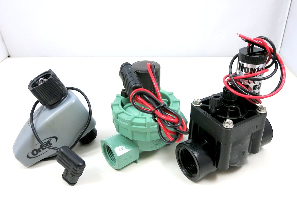
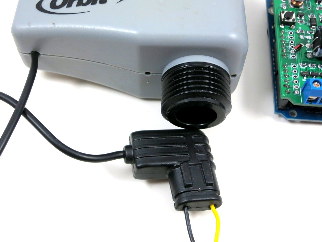
Is there any easy way to tell latching solenoid valves from 24V AC valves? Yes. Latching solenoid valves usually come with a special plug, and the two wires are usually colored differently because the solenoid has polarity. 24V AC valves usually come with just two wires colored in the same way (because AC voltage has no polarity). Here are some examples of latching solenoid valves. Note the special plugs and/or different wire colors.

IMG_0072IMG_0078

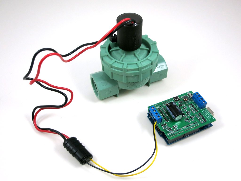
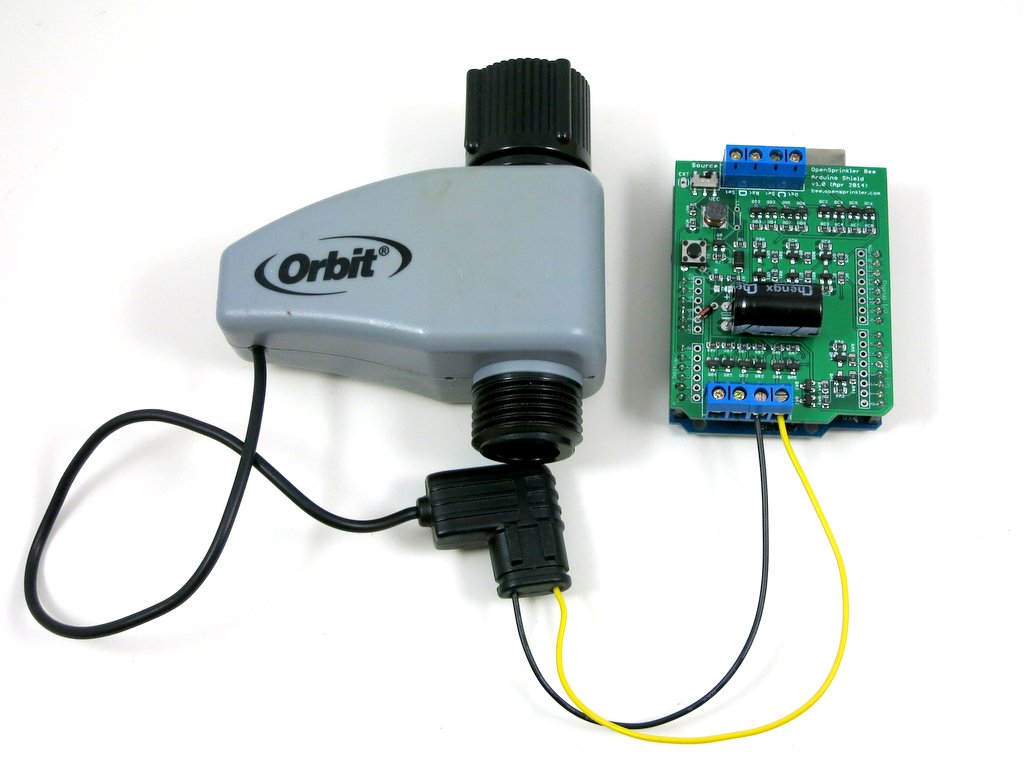
For valves that come with stripped wires, simply attach them to the screw terminal blocks on OSBee shield. For valves with special plugs, you can cut and strip two pieces of wire (20 to 24 AWG): insert one end of the wire to the plug, and the other end to the screw terminal block.

IMG_0080IMG_0077

How to open or close the latching solenoid valve? Electrically, latching solenoid valves have quite low coil resistance (a few ohms). To open the valve, you apply a momentary positive voltage on the coil. The specific voltage depends on the valve specification, but it typically varies between 9V to 22V. To close the valve, just reverse the voltage polarity. The important thing to keep in mind is that the voltage is applied as a pulse — usually 25 to 100 milliseconds. Because the coil resistance is so low, the instantaneous current is very high, up to a few amps. So you can’t apply the voltage continuously (or it will smoke the coil or the power supply!) In addition, it’s better to first build up the voltage into a capacitor, and then dump the charge to the valve from the capaictor.

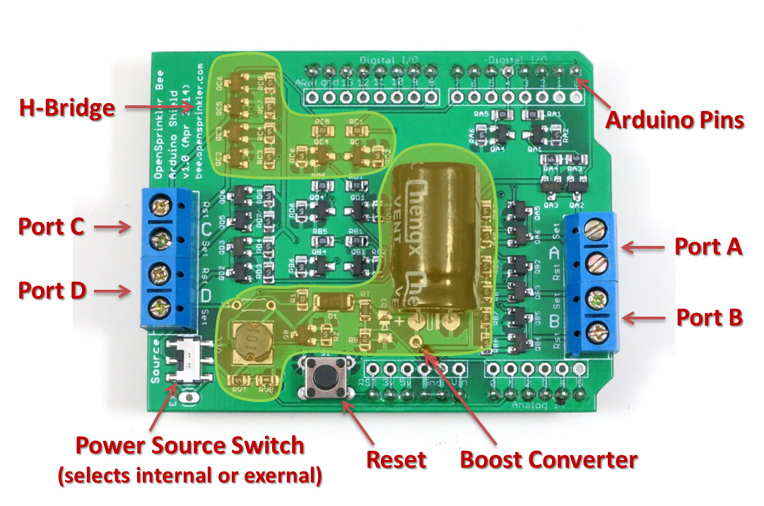
How to generate such a high voltage from Arduino’s 5V or 3.3V pin? It’s by using a neat circuitry called ‘boost converter‘. The Wikipedia has plenty of information about how it works, but the basic principle is to use a MOSFET switch, an inductor, a diode, and a PWM signal to build up the charge into a capacitor. This way you can generate a high voltage from a low-voltage source such as AA batteries.

How to apply a voltage in both polarities? This is by using another neat circuitry called ‘H-Bridge‘. The H-Bridge is made of four MOSFET switches. By closing the pair of switches in each diagonal direction, you can apply voltage in either positive or negative polarity. Because you also need a state where no voltage is applied on the solenoid, that’s three states in total and hence two microcontroller pins are required to produce three states. Wait, why not directly use two microcontroller pins to apply the voltage? Well, microcontroller pins can neither handle high voltage nor provide high current, so you need MOSFETs to help switch high voltage and high current using only logic signals from the microcontroller.

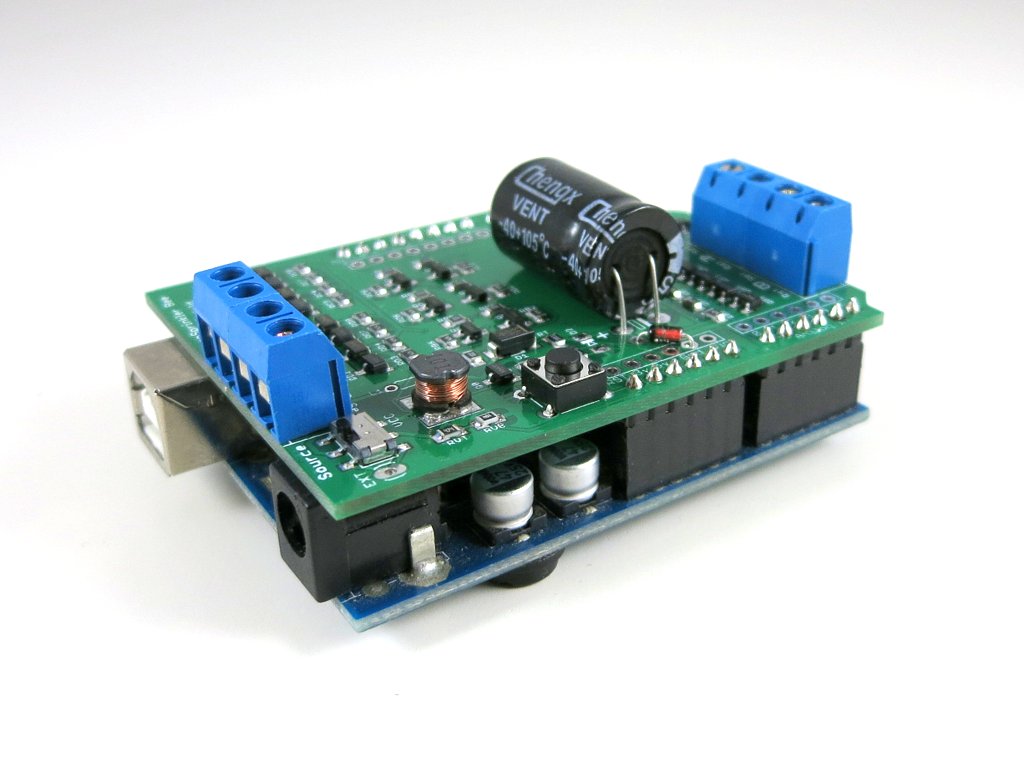
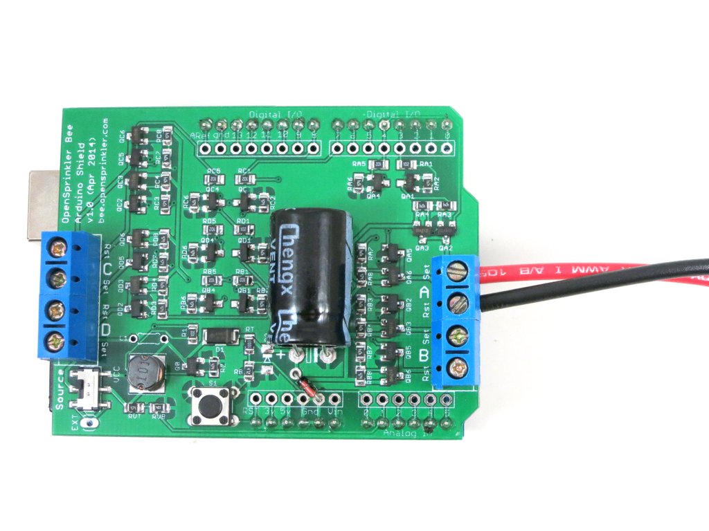
With all the technical concepts explained, here is the diagram of the various components on the OSBee Sheild:
osbee_shield_diagram

The shield can switch 4 independent valves / zones. The boosting voltage is software adjustable — anywhere from 9V to 24V. An Arduino library with three demo programs are provided in the OSBee Github repository. For details, please refer to:

OSBee Shield v1.0 is now available for purchase at the Rayshobby Shop. Thanks!

31 Responses to “Announcing OpenSprinkler Bee (OSBee) Arduino Shield v1.0”

  1. Fahmy says:

    Where is the purchase link? Is there shipping outside the USA?

  2. marco says:

    Hei Ray,
    thank you for all what you did for our geeks needs.

    I’m stuck, I have a fancy and expensive netafim DC 9v latching system which I want to get rid of and implement all the cool features of the Opensprinkler PI (basically web access and remote programming) and keeeping the existing 5 (expensive) solenoids

    I bought all what needed and when I got into deepen my knowledge I understood what is missing to drive my existing setup.

    I found out the above project is still not developed in terms of accessibility and features and plus I already got the hw for the opensprinkler.

    I found the H.bridge which may help me out to merge the two project,
    would you mind in helping in implementation?

    thank you

    https://hackaday.io/project/1223-firefighter-pump-training-system/log/3337-h-bridge-latching-solenoid-control

  3. Dave dettman says:

    We have an irrigation system with 20 valves and would like to convert to latched system. Does the Arduino support more than one osb shields? Also how long can the wire run be and still provide enough current to open/close water valves?

    • ray says:

      Unfortunately not. Any reason why you want to convert to use latching solenoids? Cost wise 24VAC sprinkler valve is usually slightly cheaper than latching valves.

  4. Dan Pagano says:

    Hi Ray,
    Sweet rig! I plan to use it on a intelligent irrigation control solution for a small organic farm. Plan on a purchase in about one month. I am still working out the detailed design on paper and plan on using the Arduino Due since I need a lot of IO. I also plan on powering it externally (load side of my solar battery charger). The Due is 3.3V digital out. Will this drive level be sufficient for the H bridge? Thanks in advance for your advice. Best Regards, dan

    • ray says:

      3.3V is fine — as you know, to operate latching solenoid valves you need a boost converter (which OSBee Shield has) to bump the voltage up to somewhere between 18 to 22V. Otherwise 3.3V itself is not sufficient to drive the valve. The good thing is that this only needs to be done when you open or close the valve, so the boost converter only needs to turn on momentarily every time you open or close the valve, and otherwise remains off.

  5. Dan Pagano says:

    Hi Ray,
    Thanks for the personal reply to my comment on Due although I think my question was poorly asked and I apologize for that. The 3.3V question was relative to the control ports not Power. Will 3.3V digital logic drive the H bridge control lines?

    Best Regards,
    Dan

  6. Pedro says:

    Great project! 🙂
    I’m trying to do something similar to this and of course I was using full h-bdriges to drive the solenoids.
    Looking at the schematic for the DC variant of version 2.3 I simply can’t figure out how you’re driving a solenoid by means of only 2 fets AFAICS… :/
    Could you please explain how you’re doing it? 😉
    TIA

    • ray says:

      OpenSprinkler DC is NOT designed for latching solenoid valves — it’s designed for AC or DC non-latching valves.

  7. charlie says:

    Hi Ray,
    I’m interested in using the OSBEE with a Particle Photon. I only need it for one valve (for now), so I’m trying to determine the basics of what would be needed to operate. I plan to use external power (I’m using a solar panel and a LiPo rider from SeeeedStudio). I reviewed your GitHub contributions and may try to customize for Photon. The Photon uses 3.3v logic, an item you’ve addressed above as viable … so I think I’m okay there. I’m not sure how to deal with the ‘internal voltage reference’ that is included in the cpp. Is it a critical component? Another thing is that the analog pins on the Photon are 16bit versus the 12bit on the Arduino. In the cpp I can update the multiplier to 4096. Will this impact the voltage-divider resistor choices (4.7k and 100k)?

    Could you confirm that these are the basic things I require?
    ::boost-circuit::
    Two analog pins (boost feedback and battery voltage feedback)
    One digital pin with PWM
    ::h-bridge::
    Two digital pins

    Thanks. I have learned a lot on your site.
    Charlie

    • ray says:

      The ‘internal voltage reference’ has to do with the reference voltage used for analog reading. For example, if you have a stable VCC and it’s 3.3V, you can use that; or if you are not sure about VCC, you can use internal reference (on Arduino it’s about 1.2V I think). This does affect the boosted voltage. Let’s say the target voltage is VBst, the voltage divider ratio is R1/(R1+R2) where R1 is the one connected to ground, voltage reference is VRef, and maximum analog value is Amax (4096 in your case). Then the analog reading A = (VBst * R1/(R1+R2)) / VRef * Amax. Therefore if you want to set VBst = 22V, you can use the equation to figure out the analog reading A that corresponds to the voltage. So if you change VRef, that will clearly change the equation.

      The basic settings you described are correct. The battery voltage feedback is not used in any demo programs, so you can ignore that — it’s meant to check the battery voltage and make sure there is sufficient battery to close the valve (to avoid leaving the valve on forever).

  8. Quinton says:

    Hello Ray,

    I downloaded the Arduino library for OSBee Shield from GitHub and copied the file to my library. I went to compile the code for each of the three examples (SimpleTest, SprinklerTimer, WebControl) and got this error message:

    C:\arduino-1.6.7-windows\arduino-1.6.7\libraries\OSBeeShield\OSBee.cpp:12:20: fatal error: Serial.h: No such file or directory
    #include

    I opened up OSBee.cpp and commented out the call to the serial header file and the code compiles. I am not sure this is the best option as I am not very experienced with code so I wanted to check your thoughts on this.

    Thank you,
    -Quinton

    • ray says:

      That should be ok. The library was written for Arduino 1.0.5 and since then Arduino has made changes to its include files. So by version 1.6.5 there is no Serial.h any more.

  9. Fred says:

    I see that the shield is out of stock in the shop here.
    On tindie, it seems to be available. Is that the case ? can I order there ?
    Regards,
    F.

    • ray says:

      We do still have a few in stock so if you buy from Tindie we can ship right away. I am in the process of redesigning OSBee to make it a standalone product (instead of Arduino shield). So if you are not in a hurry, I suggest that you wait for a few weeks and we should have the new version ready.

  10. Fred says:

    Thank you Ray.
    Interesting newproject, indeed ; I’ll wait a bit then 🙂
    Did you post some information about it somewhere already ?
    F.

    • ray says:

      I haven’t posted it anywhere. I’ve done the first pass of prototyping and is now onto the final version. The biggest change is that the new version will be standalone (it has a built-in ESP8266 chip) and will not rely on an Arduino board any more.

      • dave says:

        Any updates on the new standalone OSBee? A new blog post to tease us, maybe?

      • ray says:

        The final design is coming in this week and I will try to write a blog post this coming weekend.

      • dave says:

        Did this ever come to fruition?

      • ray says:

        The new ESP8266-based OpenSprinkler Bee is pretty much ready. This version will be a standalone OSBee (not a shield any more) with built-in WiFi. The circuit and board design have been finalized, I am in the process of finalizing the enclosure. Originally I didn’t plan to have an enclosure, but now that I’ve done laser cut enclosure for OSPi, I want all gadgets to have laser cut enclosures 🙂

  11. Swrup says:

    Hey ray,
    That was a great project in deed. But can aurdino or any micro controller take 24v ac supply to it?

    • ray says:

      No, it can’t directly take 24V AC — it needs a step down voltage regulator to convert 24V AC to 5V DC (or 3.3V DC depending on the operating voltage of the microcontroller).

  12. Claire says:

    Hi Ray

    Great product! I’ve been looking for something like this for a while and have only just discovered your site.
    Is the Arduino OSBee EOL now that you’re working on the standalone version, or will there be any more available?
    Whats the expected release date and cost for the new version?

    Thanks

    Claire

    • ray says:

      Actually a new version of OSBee is due very soon (we’ve already made a batch but I need to finish the documentation). This will be a standalone OSBee (not Arduino sheild any more) with built-in WiFi. It should be announced within a week.

      • Justin Simon says:

        Hi Ray,

        Any update on a release date for the OSBee? I am in the market to automate a set of DC Latching water valves and think the OSBee would be a great fit for this project.

        Thanks,
        Justin

      • ray says:

        Yes, I am targeting next weekend (right after Thanksgiving day). We’ve had the first batch manufactured and packaged, the only thing I have yet to finish is the introduction video.

  13. Michael says:

    Any chance of getting a schematic of this shield? Or are there any left somewhere? It’s a real shame you’re not making it anymore because it would fit my needs perfectly, whereas the newer OpenSprinkler hardware does not, or is way overkill for my specific need. I’m trying to turn a few sprinklers on and off on a center pivot, based on a GPS location. This shield would be ideal as an arduino could simply monitor GPS position, and if the pivot is in the zone where the sprinklers should be shut off, could just signal the shield to close my DC latching valves. The ability to control the pulse width, voltage, etc, is ideal for me as I need to control several valves on limited power (too much power will trip the safety system and shut down the pivot, hence I don’t want to use normally-open solenoid valves that draw 6 watts each).

Leave a Reply