OpenSprinkler User Manual — Zone Expansion Boards
With OpenSprinkler, you can easily expand the number of stations by linking zone expansion boards. Each expansion board adds another 8 stations. Technically it makes use of shift register cascading, which provides a very economical way to support a potentially large number of stations. The OpenSprinkler firmware 1.8.3 currently supports up to 3 expansion boards (and firmware 2.0.0 supports up to 5 expansion boards). That’s a total of 32 stations (or 48 on firmware 2.0.0) including the main controller. It’s possible to support more expansion boards by modifying the firmware.
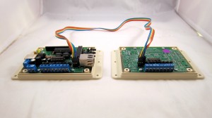
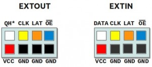
A 2×4 extension cable is used to link and cascade the master controller with zone expansion boards. Specifically, use the cable to connect the EXTOUT pin header of the previous board to the EXTIN port on next board. Watch the silkscreen on the PCB, the pin-to-pin connections you want to make is:
DOUT (a.k.a QH*)>DIN (a.k.a DATA), CLK>CLK, LAT>LAT, NOE>NOE, VCC>VCC, GND>GND
Make sure the two connectors are plugged in the right orientation. Here are some tips to help you:
- If you have received Zone Expansion Board v1.1, that comes with polarized cable connectors: each connector has a bump on it. When plugging in, always make sure the bump faces up. In fact, if the bump is facing down, you wont be able to insert the connector all the way in, so this is a security mechanism to prevent incorrect connections.
- If you have received the original versions of Zone Expansion Board, here is a simple tip to keep in mind: the extension cable connector has one corner marked by an arrow. Make sure on one end of the cable, the arrow is pointing to DOUT, and on the other end, the arrow is pointed to DIN.
If you have multipled expansion boards, you can cascade them by following the EXTOUT -> EXTIN links.
Note that you should always use the cable that comes with your expansion board: DO NOT apply the version 1.1 cable (i.e. the one that has bumps on the connectors) to the original version of expansion board, because these cables are wired differently. In any case, if you are not sure, you can always follow the pin connections above to check and verify.
Detailed instructions can be found on this page. Note that versions 1.1, 1.2u, and 1.3u/v1.4 use slightly different connection cables.
Set the Number of Zone Expansion Boards
On the main controller, press and hold button B3 during startup to enter ‘Setup Options’ mode. Keep clicking B3 until you see the option Ext. Board, then use B1/B2 to increase/decrease the number. Once you are done, press and hold B3 to set the value.


