Feed on
Posts
Comments

OpenSprinkler

Open-Source Internet-based Sprinkler / Irrigation Timer


Order

OpenSprinkler is available for purchase at Rayshobby Shop. Choose either a fully assembled product, or a DIY kit (including PCB, components, and enclosure to make your own OpenSprinkler).

Installation Tutorial

Firmware 2.1.0 Tutorial


Updates

Overview

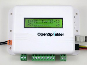
OpenSprinkler is an open-source web-based sprinkler controller / irrigation timer built upon open-source hardware and software. It works with standard 24V AC sprinkler valves commonly found in household watering and irrigation systems. You may be planning to buy a conventional sprinkler timer, but chances are that these systems provide a limited set of fixed functionality, and have no web scheduling and monitoring capability. These limitations are the main motivations for this open-source project.

This project is a collaboration between me and Chris Anderson (former editor-in-chief of the Wired Magazine).

What is OpenSprinkler?

OpenSprinkler is an open-source, web-based sprinkler / irrigation controller. It’s a drop-in replacement for conventional sprinkler controllers that are not web connected. A web-connected controller like OpenSprinkler provides the following advantages:

  • Intuitive User Interface (UI): no more messing with buttons and knobs, no more running to your garage to make a single sprinkler program change. Instead, use web browsers and mobile apps to set or change sprinkler programs. The web interface is much more intuitive than a small LCD screen.
  • Remote Access: you can access your OpenSprinkler anywhere and at any time, whether you are at home, at office, or traveling away.
  • Smart Control: OpenSprinkler can connect to the Internet and use real-time weather data (including historic and forecast data) to automatically make water time adjustments. It not only stops watering when it rains, but also scales water time up and down based on your local temperature and humidity.
Who is OpenSprinkler for?

OpenSprinkler is for homeowners as well as business owners including churches, farms, business parks, ranches, and sprinkler service professionals. Its applications include lawn and garden watering, plant irrigation, drip irrigation, hydroponics. It’s low-cost and expandable: it can scale from a few zones for a modest house up to 48 for a large business installations. Our app lets you to access multiple OpenSprinklers together for unlimited coverage.

How is OpenSprinkler different from competitors?

Web-based sprinkler controller is not a new idea. OpenSprinkler differs from similar products on the market in the following aspects:

  • OpenSprinkler’s has a built-in web interface and runs programs on its own. It does not rely on proprietary or PC-only software. The web interface works with any modern (including mobile) browser. Our mobile app is free and supports all major platforms.
  • You can easily expand the number of stations. The cost is considerably cheaper than competing products on the market.
  • The software offers a rich set of features, such as flexible program start times, graphical preview of program schedules and logging data, custom zone and program names, support to run zones either in sequence or parallel, water time down to one second. These features are rarely found in competing products.
  • OpenSprinkler is shipped worldwide, and supports many different languages.
  • OpenSprinkler is built on open-source hardware and software. Its design files are publicly available. There is a strong educational aspect of it. If you are a technical developer, you can easily customize and extend its functionality, both software and hardware. Because it’s open-source, you can feel free to build it, program it, modify it, or hack it! The design, including schematic, PCB, and parts list can be found in the Download section.

Additional FAQs

Buy OpenSprinkler from Rayshobby Shop.


Leave your comments and suggestions at the Rayshobby Forum. Thanks!

Contribute to the project through OpenSprinkler GitHub and Rayshobby Wiki.

Previous hardware release videos and notes are archived here.


83 Responses to “OpenSprinkler — Open-Source Internet-based Sprinkler / Irrigation Timer”

  1. Luke says:

    You may want to leave a link of this webpage in the youtube video 🙂

  2. David says:

    awesome!!

  3. Andrew says:

    Ray, nicely done!

    A very neat and tidy, open source project that is well implemented.

  4. Buzz says:

    The zones should run sequentially not together. This is important to keep water pressure up for larger zones. So in your example where you set program 1 with valves 1 and 2 for 1 minute. Valve 1 should run for 1 minute and then valve 2 should run for 1 minute sequentially. Other than that, awesome project!

    • ray says:

      Hi Buzz, thanks for pointing it out. That’s a good point. The main reason that I am allowing simultaneous zones is because I want to use the same controller for other purposes too. In any case, the behavior can be changed by modifying the code and reprogramming the MCU.

    • Nelson says:

      Hi Ray. As Buzz mentioned, the zones should have an option to run sequentially. As you know this is how commercial timers work. They also allow you to have more than one program – typically 2 (program A and B). I was wondering if it would be possible to modify the program to allow “how” the zones turn. Currently when a certain date/time is met – the 1st zone turns on, runs its time, then the next, etc. This would be the normal use. But I would like an additional “program mode” where I can tell it to turn on Zones 1, 2, and 5 (skipping 3 & 4) all together on a specific day or days. Furthermore the times for those zones would be unique to the sequential program. Do you think this is possible? Also, I have a Pump Relay to turn on/off the pump in my deep well – does your controller have an option to turn on/off a pump relay? Thank you! Great project!!

      • ray says:

        Nelson, the new interval program has just been released in GitHub. I have to yet write a blog post about it, and make a short release video to explain. The new program has a number of added features, the main ones are: 1) supporting up to 64 programs (mainly constrained by EEPROM size), each program has individual days, stations, start time, end time, interval, duration, 2) a choice between running stations sequentially or allows parallel running; 3) a graphical plot that can help you preview each day’s schedule. While each program runs all stations with the same duration, you can add separate programs if stations have different duration time. I should post about it tomorrow.

        Pump relay is already supported since the previous software version: it’s called Master Station. You can assign any of the first 8 stations as a master station, which automatically turns on when any other station is on.

  5. Bill Hunt says:

    Awesome!

    However, to be useful to me, I need at least 10 zones (ideally 12), and input from a rain detector. Would be fantastic if you supported those features one day.

    • ray says:

      Bill, yes that’s possible. The controller uses a 74HC595 shift register to allow 8 outputs from only 3 MCU pins. You can cascade a second shift register to expand that to 16 and still using only 3 MCU pins. The Arduino ShiftOut tutorial has an example (see Example 2).

      The main reason to limit it to 8 is to keep the controller small, since going beyond 8 would require space to put another IC and additional terminal blocks. That being said, I found that the commercial timers usually have all valves share a common (COM) wire, so that can reduce the number of terminal blocks by half. I will definitely consider this for the next hardware update.

      Great idea about rain detector. In fact, I’ve also been thinking about it recently. I’ve studied a couple of wireless rain gauges, but they seem to have difficulty transmitting signals over long distance and across walls. I will look into this more. An immediate feature I am implementing right now is to allow the controller to grab weather information from online websites, and use weather forecasts to better adjust the watering schedule.

      • plantpark says:

        otherwise ,you can connect your rain gauges to the internet ,then the controller can update the real time rain date ,isn’t easy?

  6. gordon says:

    This looks pretty feature-packed and nice, however I’m missing two things. First, a battery-backed RTC on board. Configuration is saved to permanent storage I reckon, so why should a power outage throw the schedule off? Granted, there seems to be an I2C header somewhere, but this cries for being on board. Lift the RFM12B up a bit, it’ll probably fit underneath :).

    More importantly though, external contacts for an “emergency all valves off” functionality that is wired and is completely independent of the MCU. If you use the kit inside, a software error leaving the valves accidentally open is a disaster that will (*will*) happen. Simple hardwired shut-off logic (obviously so that it can only be turned back on manually) with two pieces of wire laid on the floor or something to detect water overflowing, poof, problem solved.

    • ray says:

      Gordon, my first design actually had DS1337 RTC on the board. But I removed it in the end because I feel mostly I will use the web-interface, and since it’s online all the time I would only need periodic NTP syncs to keep the time accurate. Also, the schedule is saved to external EEPROM, so it won’t be lost upon power outage.

      The I2C headers (SCL and SDA) are reserved at the center of the PCB (together with some others in the 2×5 pin header space).

      Good point about the emergence cut off. I did consider two ways: the first is that at any time, press and hold the second button will stop all valves operations (there is also a button on the web interface that performs the same functionality); the second is a watchdog timer that prevents the MCU from going into zombie status. Ah, I see that you mean an automatic way to detect water overflow and shut off. Yes, that’s something that should be considered. Thanks for the suggestion.

      • gordon says:

        Consider this: you leave for a vacation, two weeks or three, whatever. Of course there is bad drought, because that’s when you go on a vacation :). You leave thinking your plants are safe, because you have the sprinkler.

        Comes a stormy night with some power outages that take your (internet) router with them.

        The valve controller restarts just fine, but no internet, no time, no schedule, no watering. You arrive back two weeks later to see your once-green garden having been made part of the Sahel belt.

        Long story short: the RTC does make sense, IMHO. Without it, the controller is highly dependent on things (internet connection) that it should not be dependent on for normal operation. This may obviously be just a plain difference in points of view: if you look at the valve controller simply as an extension of your arm, then no RTC is fine; but if you look at it as an autonomous device, then what use is something that inherently deals with time without the time?

        You say that the I2C connector is reserved. In that case broken-out I2C connections would also be highly desireable for added sensory circuits — surely the last thing you want to do is water in 110°F (thus basically cooking every plant, or giving them a cold shock, depending on your water source) even if the schedule says so. I could probably come up with a couple more scenarios.

        Don’t get me wrong. This thing is awesome. The idea is great. It being open is absolutely wonderful. It’s just that in this form the hardware leaves a bit to be desired — and I am only a sunday gardener.

        You have an absolutely great start, but this is the stage where you should contact people who know your subjects (the plants) and pump them for information as to what they would like to see. Even if you don’t implement the software side, the hardware shouldn’t be the limitation. Limiting hardware I can buy off the shelf, for comparable amounts of money, and I don’t even have to solder.

        This is your edge.

      • ray says:

        Gordon: those are wonderful points. Let me respond to some of your comments as I did think about similar questions when designing the circuit.

        – The MCU does keep the time running even if the Internet is off. This is a feature in the Arduino Time library, though the time will drift depending on the accuracy of the crystal. That being said, if there is a power break (hence time is reset) in conjunction with broken Internet (hence no time sync), the controller will not be able to get the correct time at all. Considering this, I will definitely add the RTC and battery backup in the next hardware update.

        – About the I2C connector, what I mean by ‘reserved’ is that the PCB does have pin headers for them (refer to the 2×5 pin headers in the center, which include VCC, GND, D3, I2C and SPI). I do expect people to extend the capability of the controller by adding additional components, hence I left space for pin headers. Sorry about the confusion.

        – About sensors, my plan is to have the controller talk to sensors through wireless. There is a slot reserved for RFM12B, which is a wireless transceiver. So a rain gauge that has the same transceiver can talk to the controller wirelessly. But my immediate plan is to modify the code to grab weather information form the Internet. This way at least it can use weather forecasts to adjust the watering schedule.

        – About the cost, certainly a DIY product cannot compete with mass-produced commercial products in terms of price. But I consider ‘open-source, programmable, and Ethernet connected’ are the biggest selling points that no commercial product offers at the moment. If this project takes off and we are going to manufacture more, the cost will definitely be lowered.

        To continue this conversation, may I ask you to post further messages in the Google discussion forum? WordPress has a limited reply depth, and the Google forum would be a better place to continue the conversation. Thanks.

      • gordon says:

        Sorry — I don’t do Google on principle.

        But I believe we have reached a point where I don’t really have anything else to add to this fine discussion. I made my points, and you seem to be open to (some of) them, and this is what matters. Just ask hardcode gardening people for their views.

        I just want to make one thing crystal clear: the remarks about the “limitations” and the “price point” were not indended to be insulting, inflammatory, derogatory or anything of the kind in any way. Quite the contrary — I understand the openness and its advantages very well (hence was the half remark, “even if you don’t implement the software side yourself” — software is easy :), especially with the ‘duino), and appreciate it very much. If my way of saying things seemed to have been insulting in any way — I apologize; english is not my first language, and this is just about the best I can do there.

        I will however check back from time to time and maybe even become a customer in a couple of months (it’s not exactly irrigation season in the northern hemisphere now :)).

        Cheers,

  7. Jaime Branco says:

    Very cool project.
    One question is it possible to see if water is running and if not power down the pump.
    Because I have already burn 2 pumps because of them working and for some motive don’t pull water.

    Jaime

    • ray says:

      Yes, that would be a good feature to have. I don’t know what’s the easiest way to detect running water (should be possible to use a sensor outside the water pipe to detect flow). Ideally it should be a built-in feature of the pump (i.e. sending a feedback signal about water status). But I don’t know if there is such a pump.

      • I believe RV systems have a pressure sensor. They turn the pump on when the pressure drops (indicating taps are open) and off when the pressure builds (indicating taps are closed). Perhaps something similar would work.

  8. Gerg says:

    All good sprinkler controllers will allow two solenoids open at one time. On many systems, opening a third will exceed the transformer’s output (typically around 1A) even if water pressure allows otherwise.

    On many systems, solenoid #1 is frequently used to act as a master valve, which is especially important for people who have a gray water system. Accordingly, in this configuration, you must have valve #1 plus whatever zone is active, open.

    I do agree allowing more than two solenoids is asking for trouble and allowing more than three is downright a bad idea. Just the same, the system absolutely should allow for two concurrent solenoids; a master plus zone.

  9. Sid says:

    Neat & awesome!

  10. dennis says:

    ray –
    is your device capable of dealing with inputting a password to connect to the house network? if it does, i think i have found my replacement for that god-awful, difficult to program RainBird in my basement!!

    thanks!

    • ray says:

      Dennis: as I explained in this page:
      http://rayshobby.net/blog/?page_id=730#network_connection
      the controller does not include a WiFi chip, because of the cost and the lack of robust open-source solutions currently. It does have a Wired Ethernet port (RF45 port). That’s why you need to use a WiFi repeater to provide the WiFi connectivity to it. Your WiFi password will be set up in the repeater, so the controller does not have to deal with it. This makes a lot of sense because WiFi repeaters are not very expensive (cheapest around $20-$30), but more importantly, it delegates the management of wireless security stuff to the repeater, so it’s a much more robust choice.

  11. Scott says:

    Can you give a link on where you got your parts?

    • ray says:

      I don’t know. The webpage did not specify the operating voltage of the valve, so I can’t tell.

  12. Jaime Branco says:

    You ship from what country???

  13. David says:

    Very well done and very impressive programming both on the embedded site and webpage. ! Apparently is works too well – as I see the lawn in the back really needs cutting. lol

  14. Eloy says:

    Hi Ray,

    Fantastic project! Thanks for open sourcing it. There are lots of things here that people can learn from.

    I have a couple of questions:

    1. What is the reason you decided to go with water valves different from the Orbit valves that you blogged about in the past? Are the ones that your new controller handles more common? Are they easier to drive than the Orbit valves?

    2. Did you go with an external EEPROM chip because the 8 kbits of EEPROM on the ATmega328 are not enough?

    Good stuff; thanks again.

    Cheers,

    Eloy Paris.-

    • ray says:

      Hi Eloy,
      1) Yes the 24VAC sprinkler valves are more common in landscaping and home irrigation systems. The orbit valves I blogged about before are typically used in battery-operated controllers and are not as powerful. The advantage is that they are very power efficient, but the downside is that you can’t really do much with a battery-powered option (e.g. no Ethernet connection). It’s certainly possible to modify the sprinkler valve controller to work with the orbit valves, but I don’t know how useful that will be. The 24VAC valve are often cheaper.
      2) Yes, I was worried that I will run out of the EEPROM size of the ATmega328. Consider that I need to store a week of watering schedule in EEPROM, it’s better to have some extra space.

  15. Matt says:

    Ray-

    This is incredible, i have been looking for a timer to automate my planted aquarium for months, and the best I could find would only operate 2 zones at once, severely limiting options. for not a whole lot more than that controller, I could buy your kit, bunch it with relays and have a networked timer to control the powerstrip under my tank. Perfect solution. Thank you for all your work in creating such a valuable package, and for allowing DIY’ers like myself access to a kit instead of just the finished product.

    Any chance that the kit will include a backlit LCD in the future?
    Also will the programmed schedule continue after a power outtage? Would it lose the time during the outage? I know that it will keep time without internet (sort of) but will the time be reset with an outage.
    Again, great job with this, I’m very impressed!

    Matt

    • ray says:

      Hi Matt,

      Yes, the backlit LCD is being planned for the future. I actually wrote a blog article about a cheap backlit LCD I found on eBay. That will be used in the future.

      The program schedule is stored in EEPROM, so it won’t be lost during power outage. The controller will obviously lose time during outage. But you can add a backup battery. Basically you need a 6V or 9V battery, connect the positive lead with a diode (such as 1n4001) in forward direction to pin 5 of LM2574N regulator (which is also the positive lead of C1), and battery negative to ground. This way, when there is power outage, the battery will provide power to keep the microcontroller running (and hence the time).

      • Matt says:

        Excellent, with a backup battery installed, when the power came back on the program would run from memory, and not need a network connection correct? Then when the network came back up, it would update only the time and re sync?
        I will be placing an order soon!
        Thanks for your reply!
        Matt

  16. Daniel says:

    Hey There,

    I have ordered one of your kits, cant wait to get the soldering iron out and put it to use!

    The only question I have, is regarding, my bore it needs a 24 volt connection which tells it to turn on, similar to a master valve, is there an easy way to setup one of the outputs as a master, so when a valve is opened it turns on my pump?

    Thanks in advance.

    Dan
    Perth Australia

    • ray says:

      Dan, you can assign one of the zones, say, station 1, to the master valve. Then when you set schedules, always set station 1 to open together with other stations.

  17. Rob says:

    Hey Ray cool project!

    Can you remote access this system?

    So if I’m away on holiday and decide that I want to alter my watering schedule can I log in to the system and make the changes from anywhere?

  18. Alex Lee says:

    Nice project.
    I had an almost identical idea i’ve been sitting on and when Chris mentioned this site on DIYDrones I immidiately ran over here to check it out.
    I was thinking of linking to weather data to check on rainfall in my zip over the last few days to “water as needed” my yard. This would be in lew of having to maintain a rain guage..
    so basically if rainfall fell below x average amount in the last 72 hours, water the yard. and keep doing so untill mother nature took back over…

    thoughts??

    • ray says:

      Hi Alex, I’ve been working on the ‘weather’ feature lately. It uses data obtained from Google Weather API to detect current weather (and forecast) condition. You can check out my most recent blog article:
      http://rayshobby.net/blog/?p=1500
      I don’t think it tells me the amount of rainfall during a period of time. This data might be available on other websites.

      • Alex Lee says:

        then perhaps a cheap guage would benefit.. if water is low then water needed is yes, and if rain forcast 24 hours is yes then hold off watering. if this happens again in 24 hours or if water not see =72 hours, then water now.

        you can really customize this.. and save much money on water by looking back and forward and making an educated guess on when to water.

        I love it.

  19. Alex Lee says:

    forget I said anything. looks like you want to hook with google api..
    I’d love to see this work out..
    I’ll probably order soon to get ready for the upcoming season.

  20. Adam says:

    I think this project is a great idea. As a suggestion, you should look at integrating support for either xPL or xAP, in order to allow integration with a large home automation system. e.g. either the home automation system could update the schedule and other parameters, but also directly operate the individual stations.

  21. Michael says:

    Outstanding project. I purchased 2 of these and have completed the first one with no problems. This is the first time I’ve built an electronics project like this and am extremely impressed with the quality of the kit … Well done Ray!!!

  22. Max says:

    Ray I have a simple electro mechanical device that basically relies on weight to turn a mercury switch on and off. I have a tray of plants sitting on this device and when they have enough water, they are heavier than the weight. This would be on the first station. I was wondering how I could use this to vary the watering percentage for the other cycles.

    • ray says:

      OK, I don’t fully understand the setup you described. Where does the plant get water? Is that controlled by a water valve? If so, you may be able to use the sprinkler controller to turn on or off the water. Otherwise I a, not sure.

  23. Max says:

    Reading my first comment again I see I was not clear. The plants on the device are watered by station one water valve (along with many square metres of others on this station). The device can give me a voltage, either on or off, when there is sufficient water, depending which way I tie the mercury switch on to the device. The idea is that this station starts to water and the device signals when there has been enough water. From this, the system is required to adjust the water budget of the other stations accordingly.

    • ray says:

      Ah, I think I understand. So basically, you want the controller to receive the signal from the device (either on or off), and then control the water valve so it can start or stop the watering. Is that right? The OpenSprinkler does not do this directly, but it’s very easy to modify the code to do that. That’s the benefit of a programmable controller — you can change its functionality by changing the code 🙂 More technically: you can use the digital pin 3 on the OpenSprinkler to read the device signal, and then starts or stops the water valve accordingly. This would be pretty easy to do programming wise.

  24. Martin says:

    Great product Ray, impressive amount of thought was invested 🙂

    I see the whole thing as a hardware platform, not necessarily used for watering projects. I myself am working on remote heat pump monitoring and controlling system and see the potential your hardware has for it (currently using NaNode).

    I have couple questions, if you may please.

    1) Why did you chose 8Mhz resonator instead of 16Mhz crystal? My project requires precise timings because of IR timing precision requirements, and I am not sure if I could use your hardware unmodified.

    2) The hardware could be more universal if you’d bring more of the analog pins out to a header/connector. I will also use thermistor to monitor room temperature, up to three Current Transformers for energy consumption monitoring.

    3) Finally, maybe a dumb queston, but I am shooting it anyway: Have you tried if the 74HC595 will pass PWM to the selected valve pin, in case I decide to use it for other purpose? Google answers it is possible (http://www.arduino.cc/cgi-bin/yabb2/YaBB.pl?num=1258679906), but I’d like to hear from first hand experience.

    Thanks
    Martin (Bulgaria)

    • ray says:

      Martin,
      Indeed the hardware can be used for other applications. Some, which I have tried, are documented on this page. The hardware design is compatible with NaNode (some pin assignments may be different). To answer your questions:

      1) The 8MHz resonator is just for simplicity. Note that the MCu runs at 3.3V so that it can interface with ENC28J60 and RFM12B (both require 3.3V) directly. According to ATMEL datasheet, 16MHz under 3.3V is slightly overclocking. While it should work just fine (such as JeeNode), I decided to go with 8MHz for stability. Also, using resonator is because the controller doesn’t need precision timing — it does NTP sync periodically to synchronize time anyways. You can certainly replace the resonator with a crystal (soldered from the front) and two caps (soldered on the back).

      2) Among the 6 analog pins, 4 have been assigned to button read and LCD display, the only two remaining are the I2C pins (A4 and A5, or SDA and SCL). I do have pinouts for them at the center of the PCB.

      3) Yes, I’ve tried this. On this page, check the second video.

  25. Martin says:

    Thanks, obviously I haven’t been reading carefully (embarassed)

  26. Jay says:

    What sort of over-current protection does your controller have and what is the maximum current that each zone can control as well as the total current the controller will handle across all zones simultaneously?

    Regards,
    Jay

    • ray says:

      Hi Jay, the current version has no over-current protection. Each zone can draw as much current allowed by the triac (which is 800mA). However, in practice, the total current is limited by the transformer’s current rating. For example, the transformer I am using is rated at 750mA, which means if any zone draws more than about 600mA (the controller circuit draws about 150mA), the transformer voltage would drop significantly and trigger a reset. This is the case, say, if a zone is open and the two wires are accidentally shorted. In future version, I am considering adding a PTC fuse to limit the total current.

      • Jay says:

        Ray,

        Thanks for the quick reply and one more question. My current systems consists of 15 zones and I have read that there is a way to expand your controller beyond the 8 but I am not clear on how that is accomplished and how the additional 8 would be controlled as the software only appears to have a total of 8 zones.

        Regards,
        Jay

      • ray says:

        Jay, yes it’s possible to extend to 16 stations by adding another shift register. The basic idea can be found in this Arduino shiftout tutorial. You are correct that the software has to be updated to support 16 stations. At the moment, the simple web-based control program has been updated to support 16 stations. You can find the source code on my Github repository. The main demo program has not been updated to support 16 stations yet. I will find some time to work on it soon.

  27. Jerry Gomez says:

    This product is interesting too, http://www.hydrawise.com/

    • ray says:

      Jerry: thanks for pointing it out. I am aware of HydraWise, and I want to point out the main differences of OpenSprinkler with it:

      • – OpenSprinkler provides open-source hardware and software, its functionality can be modified or expanded through re-programming the MCU.
      • – It is considerably cheaper than HydraWise: an unassembled OpenSprinkler kit costs $65-$80, and an assembled kit costs $130, while Hydrawise costs $400.
      • – It is also considerably cheaper to expand the number of stations: each OpenSprinkler extension board (8 stations) costs about $30 (to be released soon), while for HydraWise it requires another controller which costs $400.
      • – HydraWise charges a monthly fee except for the basic one with budget features.

      On the other hand, I agree that HydraWise excels in its polished software and website design, and its built-in WiFi adapter (for which OpenSprinkler requires an external wireless repeater or bridge). Overall, I think they target different communities: OpenSprinkler is currently targeted towards hobbyists, tinkers, DIYer and the open-source community, while HydraWise targets commercial users and people who have little experience with electronics and programming.

  28. Jerry Gomez says:

    Agreed, this is an exellent option, compared to high cost alternatives.

  29. Luis García Pimentel says:

    Hi, I’ve been reading into your project and I find it very interesting. A question I have now is if you have unassembled v1.1 kits for sale, as I am right now trying to save every penny and also I like to build things myself.

    Cheers for a nice and well presented project.

    • ray says:

      @Luis: the v1.1 DIY (unassembled) kit will be available on Monday. I have been working this weekend to finish up the assembly instructions so that I can release it first thing next week.

  30. Mario Arce says:

    Ray,

    I would like to buy your unit it is perfect for what I am trying to do. My question is I would like to use this device for a splash pad requiring 5 to 6 valve controls however I have to have the ability to.

    -Run the valves in random mode
    -Sequence the valves in 1 minute intervals then cycle back . Example Valve 1(30 seconds) Valve 2 (30 seconds) etc then repeat

    Could you possibly help me to figure this out?

    Thank You

    • ray says:

      Mario, what you described should be straightforward to implement. I have an interval schedule program that may be directly applicable to your task. Basically the program allows you to set an interval for each station (say, station 1 turn on for 30 seconds every 1 minute, station 2 turn on for 20 seconds every 1 minutes etc), and it will run valves in sequence. Currently it runs each valve in order (for example, if stations 1, 2, 5 are all scheduled to open in the same minute, they will be serialized and run in that order. Should be easy to modify if you want to run them in random order.

  31. Mario Arce says:

    I would like to order this as soon as possible as my splashpad is nearly complete. What products would I need to order? Feel free to email me directly if you feel it is best. I would like to order the complete system if possible.

    thanks,

    Mario

  32. ed0408 says:

    Ray,
    You have a very good project which i think i can incorporate with mine. I am planning to put up a small green house. Can i incorporate a temperature and humidity data logger with your controller so that i can fire up the sprinkler once a certain temperature or humidity is reach (and reset the timer) or fire up when at a certain time whenever temperature or humidity remains normal?
    Thanks,
    ed

    • ray says:

      I’ve used temperature sensor in another project, which is pretty straightforward. I haven’t experimented with humidity sensor. Most of these sensors output analog signals, so it’s pretty easy to wire them to an available analog pin, and modify the code to periodically read the sensor values.

      -Ray

  33. Payday Loans says:

    Good day! I know this is somewhat off topic but I was wondering if you knew where I could find a captcha plugin for my comment
    form? I’m using the same blog platform as yours and I’m having trouble finding one?
    Thanks a lot!

  34. George Myers says:

    Hi,
    Great project.

    I was watching one of the EEVblogs and he was showing your AASaver. Clicked on his link to your site and first thing I see is the OpenSprinkler project. I have been crawling the internet for the last 2 months trying to find a solution to a project I want to do and you might have the answer.

    My project is to put a dedicated water valve at each location where I have plants/trees. I want to run one power line and pig tail off each location to the valves and have a controller at each location. Right now I have 26 location where I need a valve and most likely will add more valves in the future. So far I have not been able to find any solution to this. I live in a desert part of Arizona so I want to control the water flow as much as possible.

    Would your OpenSprinkleer Bee/OpenSprinkler do what I would like to accomplish? If so a wireless solution would be more than I hoped for.

    Again, great project and could you give us a little more info on your wireless valves you have planned.
    Thanks
    George

    • ray says:

      Hi George, sounds like the OpenSprinkler Bee may be what you need. It’s an RF wireless client that is controlled by the main OpenSprinkler controller. You do have to consider the RF transmission range. The RFM12B I am using has a maximum transmission range of about 300 meters. How far is each location apart from the others? If they are not too far, you may consider simply using the existing OpenSprinkler controller plus a few extension boards, and run wired connections to the valves. If you use sufficient thick wires, they can run 250 meters long. The other option is to have the valves all close to each other, and run long water pipes/hoses to each location you need.

      -Ray

      • George Myers says:

        Hi Ray

        Thanks for the suggestions/info on your reply.

        I was hoping you would say the Bee would be what I needed. What I want to do is only run one water pipe and electric wire over my entire area and tap off the wire and pipe at each location. The transmission range of 300 meters for the wireless would be more than enough to cover the back yard. If I plan it right I think I could also use one run of wire as I doubt when you include the pig tail to each valve I do not think I will be over the 250 meter mark. I would only have one valve open at a time in this scenario.
        What is the cost of the Bee?
        Depending on cost I may have to use less boards, and control maybe four outlet T’s with one board and put manual valves at each of the four outlets to adjust the flow until I get them adjusted to more or less fill around the plants/trees to about the same level when the main Bee controlled valve is on.

        George

  35. Tim Harper says:

    I ordered my kit recently and installed it on Saturday. It’s working flawlessly! However… the UI could use some work. I’m excited to get in and hack it to see what improvements I can make.

  36. Mark says:

    Good Evening Ray,
    Everything (controller V1.2u and extension) was working perfectly until this evening. We experienced a brief power outage and the controller fails to connect now that the power is restored. I have verified the ether-net cable and router, reset the power and the controller parameters to no avail.

    I am running the units in manual mode but would like to get them connected again for more control. Any insight you have would be greatly appreciated.

    I have also run the diagnostic and it continually cycles through the 16 stations turning water on off but never concludes.

    Regards
    Mark Hyer

    • ray says:

      Hi Mark, are you using DHCP (dynamic ip) or static ip? You can find this in the options (press B3 when powering up the controller, and click B3 to go through options). If you have not updated to the latest software version (1.6) DHCP may not work with your router. I suggest that you use static ip instead. It’s certainly possible that the Ethernet controller is damaged due to power surge, but I think that’s unlikely, and if it is, it just costs a few dollars to replace.

  37. Mark says:

    Hello Ray,
    Thank you for the prompt reply. It turned out to be a security issue with Microsoft’s IPSEC protocol.
    I wrote the exceptions for the DHCP address and when the power came up it must have grabbed a new adress. I gave the controller a static address as you suggested and modified the address in IPSEC secutity and it’s working again. The static IP address will prevent this problem in the future.

    For your clarification I am running version 1.5 on the 1.2u build. I have temporarily abandon the software updates because of older Microsoft operating systems. When I have more free time I will try the update process again. The Update is just not that important now.

    Thanks again
    Mark

  38. Jim says:

    Hey Ray,

    I noticed that the IC sockets aren’t on the parts list – what type do you use and where’s the best place to get them?

    Also, there isn’t much info on the 32.768KHz real time crystal or where to obtain.

    Any help is appreciated.

    Thanks,

    Jim

    • ray says:

      Hi Jim, for getting a small number of parts I recommend Digikey.com, because they offer post-office first-class mail, which is fast and cheap. You can simply search ‘IC socket’, select the appropriate pin number, apply filter, and sort by price. Same for the crystal: just search ‘crystal’, select 32.768khz in the frequency list.

  39. Jim says:

    Hi Ray and thanks for the response. One other question I have for you is about the LCD screen. The part you have identified from Future Electronics is back ordered out 14-16 wks. I looked on eBay as you recommended and there weren’t any of the two different models available. Are there other options that would work? Is it possible to run the kit without LCD simply by web interface?

    Thanks again.

    Jim