Update: the technique described in this article is possibly no longer necessary for the current version of OSBee, as it now supports setting a different opening vs. closing voltage.
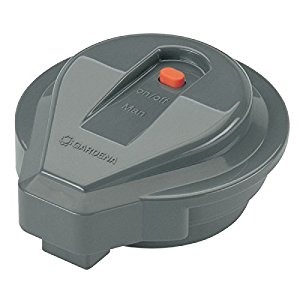
Recently when helping a customer, I came across an interesting case of how to control Gardena 1251 latching solenoid valve using OpenSprinkler Bee. This valve is mostly sold in the European market and isn’t very popular in the US market. On spec, it’s operated using a single 9V battery, and to use this valve you need to buy a Gardena 1250 controller unit. The whole assembly including the valve and controller unit are quite pricy (close to 100 bucks), so it’s not a very cost-effective solution compared to other brands. Nonetheless, it’s an interesting case that helped me understand how these latching solenoids work.
Measure the Control Voltages
The initial request to look into this valve was due to the fact that OSBee can’t seem to operate this valve correctly: it can open the valve but never manages to close the valve. This was reported by a German customer, and it caught my curiosity. To figure out the issue, the first thing I did was to check how the control unit (1250) is sending out control voltages to the valve. It’s pretty common that when operating latching solenoid valves, the control circuit sends an impulse voltage to open the valve, and another impulse voltage in the reverse polarity to close the valve. On most solenoid valves I’ve seen, the two impulse voltage (of opposite polarity) are roughly the same, and that’s also how the OSBee circuit works.
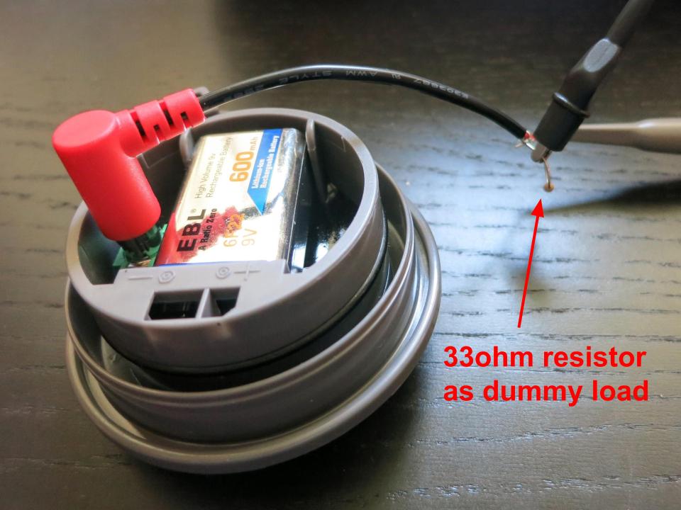 Upon connecting the control unit to an oscilloscope, I noticed something strange: no matter how I press the on/off button, it’s only sending a very short (a few milliseconds) pulse, which cannot possibly operate the valve. Then it became clear to me that the controller is in fact actively sensing the existence of the valve, and would not send control voltages if the valve is not detected. I measured the resistance of the solenoid valve, which is about 35 ohm. So I connected a 33 ohm resistor to the controller as a dummy load, and there you go, now we can observe the control voltages and pulse lengths.
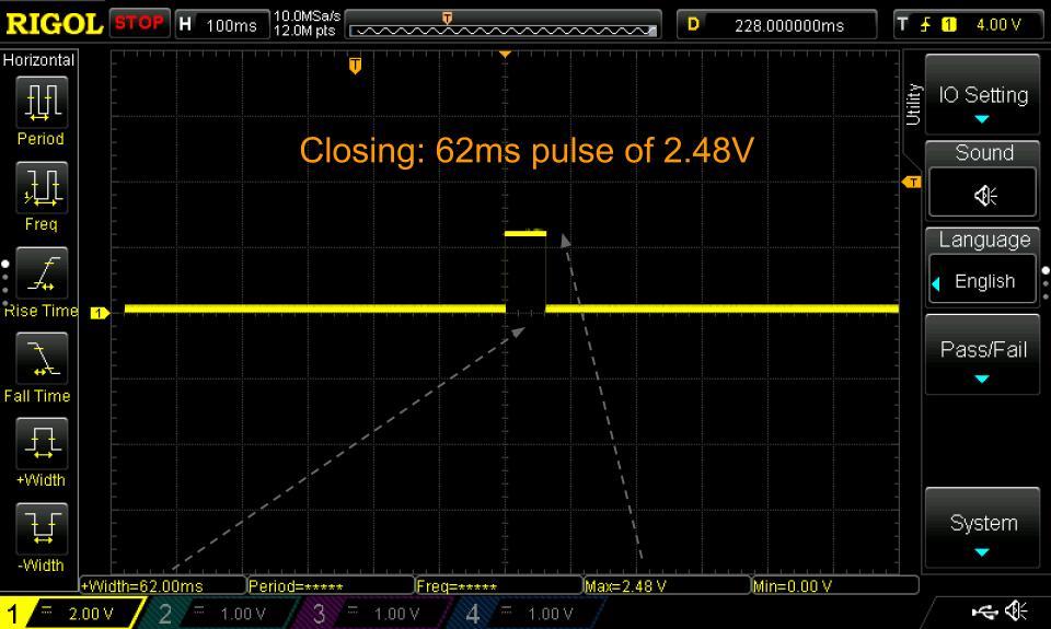
It’s pretty easy to notice the asymmetry here: while opening the valve requires a pulse of 250 ms and -7.84 voltage (this is roughly the battery voltage since my 9V battery isn’t fully charged), closing the valve only requires a very short pulse of 62 ms and very low voltage — 2.5V. This is quite strange to me: how come closing the valve only requires such a short pulse and such low voltage?
How Does This Latching Valve Work?
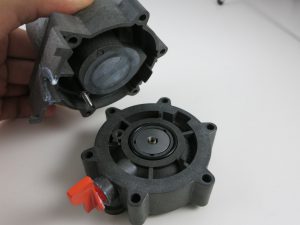
In order to figure out what’s going on here, I un-tightened a bunch of screws and opened up the valve.
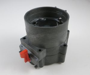

At the bottom of the valve is a pressure chamber with a spring. This is very similar to other valves I’ve seen.
The top section contains, supposedly, a coil and magnet inside, and a small cone-shaped metal piece that can be attracted to the magnet or released. It’s quite easy to observe that when opening the valve, the metal piece gets attracted (left picture above), this supposedly releases the pressure in the bottom chamber, thus allowing the water to flow through the valve. Conversely, when closing the valve, the metal piece is released and dropped to block the hole at the bottom, this supposedly allows water pressure to build up in the bottom chamber, thus stopping the water flow.
The key in making this latching is that an impulse voltage can permanently magnetize the core, thus permanently attracting the metal piece. This makes it possible for the valve to remain in the ‘open’ status without contiguously drawing current from the power source (which is unlike non-latching valves like 24VAC valves).
Observing this mechanism, it became clear to me that ‘closing’ the valve basically requires de-magnetizing the core, and that requires just a short pulse of low voltage in the opposite polarity. If you apply the same voltage and strength as before, it will start magnetizing the core the other way, thus the magnetic pole changes direction but the metal piece will still be permanently attracted!
Anyways, this is very interesting to me because previously I had no idea how latching solenoid valves work internally. Now at least I know understand this particular valve works, and this understanding will help me figure out how to get OpenSprinkler Bee to control this valve.
Use OSBee to Control the Gardena 1251 Valve
There are several issues that make OSBee incompatible with the Gardena 1251 valve, but it turns out they can all be solved without too much difficulties. The first is that OSBee by default boost the input voltage (which is 5V from USB) up to 22VDC, which is significantly higher than 9V required by the valve. This is reasonably easy to solve — by fine tuning the boosting time, I can find the sweet spot where the boosted voltage is just around 9V. This boosting time turns out to be around 80 to 100ms.
Second, OSBee by default uses 100ms pulse in both directions (i.e. both opening and closing the valve). This is very easy to change to 250ms and 62ms respectively to match the Gardena controller.
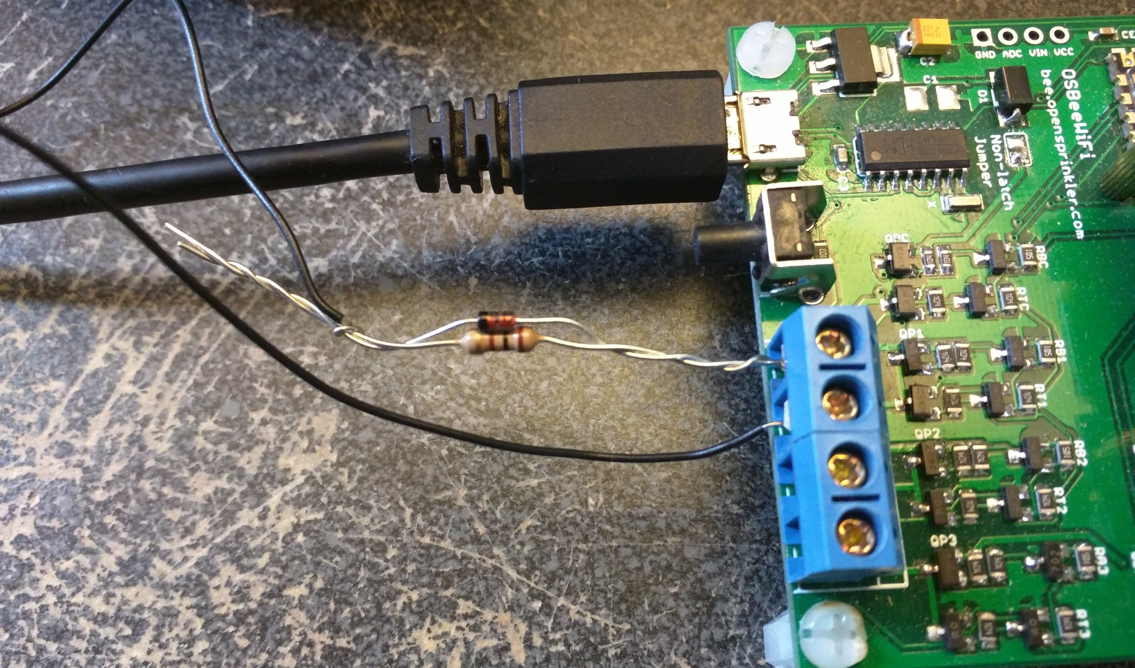
The last issue deserves more thinking, that is, opening the valve requires 9V, but closing the valve requires only 2.5V. Because the input voltage is from USB and it’s 5V, there is no obvious way to step that down to 2.5V since the boost converter can only bump up the voltage and never reduce the voltage. How do we create this asymmetric voltage in opposite polarities? Turns out that you can do so by making use of a diode connected in parallel with a 100 ohm resistor. Why? The diode is a one-way gate: when positively biased, it turns on almost fully (except the 0.7V voltage drop across it, which can be ignored here); but when reversely biased, it turns off, thus current has to flow through the resistor (connected in parallel to the diode), and that resistor will divide the voltage, ensuring that only about 2.5V falls on the valve.
I’ve attached here a diagram showing the connection. The diode can be almost any general-purpose rectifier, like 1N4148, 1N4001 and so on. I’ve also included two photos showing the actual components connected to OSBee and the valve. With this modification, OSBee can now both open and close the Gardena 1251 valve successfully. Mission accomplished!

