Note: the RF transmitter used in this article is available for purchase in the shop page.
In a previous post I described a way to use an Arduino to interface with remote controlled power sockets. The idea was to make use of the original remote control, and a high-side transistor switch to simulate button presses. This approach is generic: you don’t need to know how the remote control signal is encoded, instead, just treat the remote control as a black box and simulate the button presses. However, the downside of this approach is that it requires soldering wires and components to the remote control, which is quite a bit of work.
Recently, inspired by the JeeLabs KAKU remote switch article, I figured out a new way to interface with these remote power switches. The method published by JeeLabs uses an RFM12B transceiver, which is cool because my OpenSprinkler design has a reserved spot for RFM12B. Unfortunately after many experiments I was unable to get it to work with my switches. However, I did succeed by using a 433MHz RF transmitter purchased from SparkFun. So below I document the process of how I did it.
To begin, I took apart the remote control. The goal is to reverse engineering the signal sent from the remote control, so that I can use an Arduino to simulate the same signal. This will allow me to use a program to control the power sockets. The schematic of the remote control circuit can be found in the previous post. Basically it consists of an encoder IC (HT2262 or PT2262) and a 433MHz RF transmitter circuit.
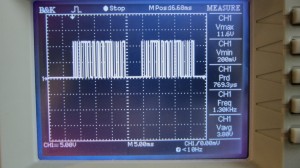
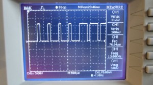
By connecting an oscilloscope to the circuit I was able to analyze the signal patterns. Details can be found in the video attached at the end of this post. Below are the patterns I observed when button 1 is pressed (corresponding to power socket 1).
The signal consists of two basic patterns: a short HIGH followed by a long LOW, which I call a ‘0’ all together, and a long HIGH followed by a short LOW, which I call ‘1’. The long part is roughly 500us and the short part is roughly 160us (so it’s about a 3:1 ratio). Each signal sequence consists of 25 bits: the first 16 bits are always ‘0000 1111 0101 0101’, which I call the ‘signature’; and the next 8 bits are the ‘command’, which correspond to the index of the power socket; finally, there is always an ending ‘0’.
For example, the entire sequence to toggle socket 1 is
0000 1111 0101 0101 1100 0001 0
the entire sequence for socket 2 is:
0000 1111 0101 0101 0011 0001 0
and for socket 3 it is:
0000 1111 0101 0101 0000 1101 0
Again, a ‘1’ means a 500us HIGH followed by a 160us LOW, and a ‘0’ means a 160us HIGH followed by a 500us LOW. When a button is pressed, the sequence is repeated several times, for robustness I guess.
Interestingly, you can OR the command part in order to toggle two or three sockets at the same time. For example, the sequence below will simultaneously toggle socket 1 and 2:
0000 1111 0101 0101 1111 0001 0
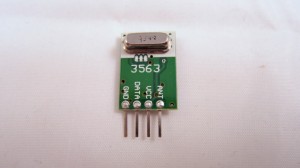
Next, to simulate the remote control signal using an Arduino, I used a 434MHz RF transmitter from SparkFun. This transmitter has only 4 pins: Gnd, Vcc, Antenna, and Data. The data pin can be connected to any digital pin on the Arduino in order to send the control sequence as analyzed above.
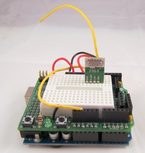
For demonstration, I used Arduino pin 10 to send the control sequence through the Data pin. The connection is as follows: VCC->+5V, GND->GND, DATA->Digital 10, ANT->a short wire. The supply voltage for the RF transmitter can be anywhere between 1.5V to 12V. The higher the voltage, the longer the transmission range. Normally 5V should be good for at least 15-20 meters. If you want the highest range, use a +12V power adapter to power your Arduino, and connect the RF transmitter Vcc pin to the Arduino VIN pin. Alternatively, you can add a voltage boost converter to bump +5V to +12V.
Below you can download the Arduino program I wrote. The code should be easy to follow.
If you have a different remote controlled power switch, you can follow the same procedure to find out the control sequence, then modify the program accordingly. A video demo is provided below:
Credits: the method is based on JeeLabs KAKU remote switch and the code is based on the kaku_demo sketch included in their RF12 Arduino library.
Note: the RF transmitter (434MHz) is available for purchase in the shop page.
Update 1: apparently if you look at the datasheet of PT2262, which I found a copy here, it explains how the encoding pattern is computed. The ‘signature’ part has to do with the status of each pin from A0 to A7 on PT2262 – whether the pin is connected to GND, VCC, or floating, and the ‘command’ part is determined by the status of each pin from D0 to D3. I compared the circuit with the datasheet and verified that the pattern I observed from the oscilloscope matches the calculation. Also, according to the datasheet and the resistor value I found on the remote control, it looks like the long delay should be about 400us and short delay 133us, which is a bit different from the 500us and 160us observed from the oscilloscope. Also, the ending ‘0’ in my sequence turns out to be a ‘sync’ bit, which is 133us high followed by 4200us low. The fact that my original sketch has worked means there is a some level of tolerance in the timings. So they do not have to be highly accurate.
Update 2: new version of remote control. A reader of this post, Chuck, sent me a question that the sketch doesn’t seem to work with his remote control. After researching this issue, we found that the new version of the remote has changed to use SMT components and also has changed the coding pattern. Chuck sent me an image of the back of the PCB. From the image and the datasheet of PT2262, I figured out the new coding pattern. Basically, the ‘signature’ part of the code has been changed from
0000 1111 0101 0101
to
1101 0111 0101 0101
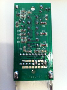 More technically, the coding pattern can be derived from the connections of Pins 0-7 of PT2262. In the newer version (from the PCB image on the left), the first 4 pins are connected as HIGH, FLOAT, FLOAT, HIGH, whereas the older version is connected as LOW, LOW, HIGH, HIGH. Here HIGH means connected to Vcc, LOW means connected to Ground, FLOAT means unconnected. Taking a look at the datasheet, you can easily figure out the actual code: LOW -> 00, HIGH -> 11, FLOAT: 01.
Chuck sent me his modified code, which you can download here.


