I went to a local cafe for brunch today, and I couldn’t be more delighted to see this poster at the cafe:
So is this where the name ‘Arduino’ came from? Not really. According to Wikipedia, the name of the open-source microcontroller Arduino comes from the following:
Founders Massimo Banzi and David Cuartielles named the project after Arduin of Ivrea, the main historical character of the town.[8] “Arduino” is an Italian masculine first name, meaning “strong friend”. The English version of the name is “Hardwin”.[9]
The poster is actually an advertising poster made by Italian artist Leonetto Cappiello. The painting was done in 1922 for La Victoria Arduino. There are apparently multiple posters, which you can find here. In any case, a pleasant surprise to find the name of my friend ‘Arduino’ on the poster 🙂
After several months of hard work, my first ‘serious’ Arduino-based electronics project is up on the project page now. Check out the OpenSprinkler – An Open-Source Sprinkler Valve Controller. This is a collaboration between me and Chris Anderson (editor-in-chief of Wired Magazine). A video demo is included below. For details and how to order a kit, please refer to the project page.
Update: check out the RFToy — an easy-to-use standalone gadget to control remote power sockets. Also, support for remote power sockets have been added to OpenSprinkler firmware 2.1.1.
For a while I’ve been looking for a way to switch household power line (110V) devices. One of the simplest options is to use a relay that is connected to the power line. This is easy in concept but quite dangerous to work with. You don’t want to accidentally touch the power line wire and shock yourself. A much better option is to use the powerswitch tail, which insulates the relay and the relevant circuity inside a plastic enclosure, leaving only two MCU pins to interface with. Much safer. But you still have to run wires between your MCU and the power socket. I am more interested in an wireless option.
Recently I purchase a set of remote controlled switch sockets from Amazon. It comes with one remote and three sockets, each of which can be individually switched. The whole package is quite cheap. The way this works is that you plug the sockets into the wall, and when you press a button on the remote, the corresponding socket will switch, thus turning on or off the device connected to the socket.
I took apart the remote control and found that the circuit is quite simple. It’s based on an HT2262 remote control encoder and a 434 MHz transmitter circuit. In fact, the schematic of the circuit is well documented in the datasheet of the encoder:
From the schematic, it’s quite clear that when a button is pressed, the input voltage is fed to one of the encoder pins (as well as the VCC pin of the encoder). Then the encoder will send the signal to the RF transmitter circuit. The RF signal will be received at the power socket side and decoded. Very simple. Now, to use my Arduino to interface with this power switch, all I need to do is to simulate a button press by sourcing a positive voltage to wires labeled SW1, SW2, SW3 etc. It turns out that the HT2262 can work with a fairly wide range of voltage: from 4V to 18V. Clearly the 5V output from an Arduino IO pin falls within the acceptable range. So I can simply connect those wires individually with Arduino I/O pins, and write a program that outputs HIGH momentarily when I need to switch a device. The only downside is at 5V the transmitting range is limited. The higher the input voltage, the longer distance it can transmit. So a more flexible design is to have a ‘source’ driver to supply higher than 5V to the encoder.
Update: check out the RFToy — an easy-to-use standalone gadget to control remote power sockets. Also, support for remote power sockets have been added to OpenSprinkler firmware 2.1.1.
This can be done by using a transistor based high-side switch. Here is a schematic:
Basically, when the IO pin outputs low, transistor Q1 (NPN) turns off, and its collector is in high impedance status. Hence Q2 (PNP) is also off. Now, when the IO pin outputs high, Q1 conducts, driving the gate of Q2 low. Therefore Q2 also conducts, sourcing +12V voltage to the encoder. The reason to use such a high-side driver is to be able to switch a high voltage (>=12V) using a relatively low-voltage (<=5V) control signal from the MCU.
I implemented this method on a small proto-board. Since the remote control has 3 buttons, I made 3 copies of the above high-side driver, and the entire circuit fits nicely inside the remote control cover. I soldered five wires out: +12V, GND, and three control wires. A picture is shown on the left.
With this modification, I can now switch power line devices such as home lights and heaters using a microcontroller. Better, I can connect the remote control with my OpenSprinkler Controller, thus I am able to control power line devices through a web interface. The video below show a demo. Enjoy!
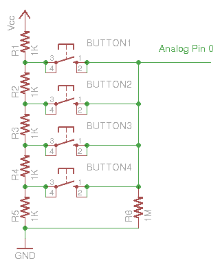
At times I feel short of digital pins on the Arduino to handle multiple button inputs. Here is an easy way to use 1 analog pin to handle many input buttons. The way it works is very straightforward: use a resistor network as voltage dividers, and then let each button feed a different voltage to the analog pin. Thus by detecting the voltage we can tell which button has been pressed.
As a downside, it cannot handle simultaneous button presses. To do that, one could potentially use resistors at doubly increasing resistance (1K, 2K, 4K, 8K…). Hence by checking the detected voltage, we should be able to tell which buttons are pressed simultaneously.