Feed on
Posts
Comments

Update: OpenSprinkler 2.0 or above uses a different switching regulator and does not require additional resistor any more. The information below is only relevant to OpenSprinkler 1.x.

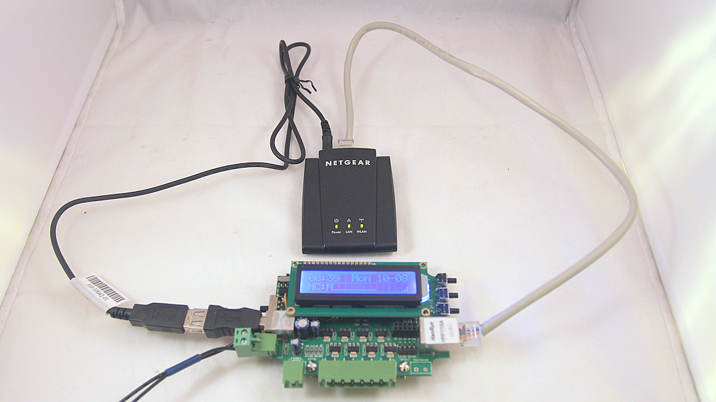
As you know, OpenSprinkler uses a single 24VAc sprinkler transformer to power both the circuit and the sprinkler solenoids. Frequently people are using a WiFi adapter together with OpenSprinkler to provide wireless Ethernet connection. So how about using the same transformer to also power the WiFi adapter? Ah ha, good question. This turns out to be possible and quite easy to do!

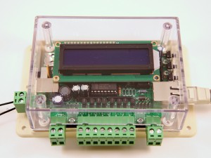
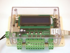
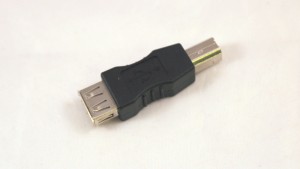
The basic idea is that many of these WiFi adapters (such as the popular NetGear WNCE2001) can be powered using an attached USB cable. One end of the cable is a USB Male A connector, and the other end is typically a 2.5mm power jack that goes into the adapter. Since OpenSprinkler has a built-in USB port (which is connected to the +5V output of the 34063 switching regulator), it can be used to directly power the WiFi adapter. However, OpenSprinkler’s USB connector is a Female B type, so the trick to make this work is to throw in a USB Female A to Male B converter, as shown in the picture below:

You can get this converter from Rayshobby Shop or at online retail stores.

Hold on one second, this is not the only thing you need to do. You also have to solder an additional 1 ohm resistor to the circuit board. The reason is that these WiFi adapters are quite power hungry: I measured that the NetGear WNCE2001 draws about 300-400mA current during operation. On the other hand, OpenSprinkler (by default design) outputs about 330mA current on its +5V output, of which 180mA will have to power the mcu and Ethernet controller. So we need to increase the current output. Fortunately this is not too difficult to do. The trick is to reduce the resistance of Rsc — current limiting resistor for the 34063 switching regulator. According to 34063’s datasheet, the maximum output current is 0.33/Rsc. So if we put two 1 ohm resistors in parallel, Rsc is effectively 0.5 ohm, and hence the maximum output current increases to 660mA, enough to power both the circuit board and the WiFi adapter. Also, OpenSprinkler v1.3u and v1.4 have already designed a spare slot for the parallel Rsc, so it’s pretty easy to make the modification.

You can reduce Rsc even further to provide better safety margin. 34063 supports maximum output current of 1.5A. To do so, you can keep putting more 1 ohm resistors in parallel until you reach the desired resistance. The reason to use multiple 1 ohm resistors is because it’s lowest value common resistor. Anything below 1 ohm will have a big price jump.

Again, if you are interested in trying this, you can get the USB converter from Rayshobby Shop. We will also throw in a couple of 1 ohm resistor free of charge!
I had the urge to send this out a week ago, but I was holding on to it because I had to hear some feedback, suggestions, and issue reports from the initial users. Now I am ready to spread the words:

OpenSprinkler Firmware 1.8.1 is available for download in GitHub, go for it!

If you haven’t updated firmware before, here are the Firmware Update Instructions.

As always, the first question I need to answer is: what’s new in this version? Here is a list of highlights:
• New features:

  • Custom station names: each station can have a custom name up to 12 letters long.
  • Per-station master operation control: each station can individually activate the master station.
  • Run-once program: similar to the manual override feature on some sprinkler timers.
  • Station delay time, and master on/off adjusted time: fine tune station turn-on and turn-off time.
  • Water level/percentage: globally scales water time up and down based on local weather conditions.
  • Automatically reconnect: improves reliability on unreliable networks.
  • Support for RTC and automatic RTC detection: keeps time running even when power or network is lost.
  • Full range of time zones: living in Nepal? No problem.

• Improved features:

  • Program now has an ‘enable’ flag which allows you to enable or disable each program individually.
  • Improved Graphical Preview feature, which shows each station’s name and scheduled on/off time.

So this is another major upgrade since Firmware 1.6. So what happened to Firmware 1.7? Well, that was a quick update for the preparation of OpenSprinkler 1.4 orders: except for added support of RTC, it didn’t have any major changes. So I had to number this one 1.8 to distinguish it from the previous version.

Also taking a suggestion from the Forum, I’ve starting using minor revision numbers (1.8.0, 1.8.1 etc.) to keep track of changes in between major releases. This way you can easily find out whether your version is up to date.

I’ve also made a video tutorial (above) for those who want a video guide on how to use this firmware. I ended up having to switch between different ways of recording, so the audio quality is not consistent. Sorry about that, and enjoy the video!

About two weeks ago we started shipping out OpenSprinkler v1.4, and I figured it is now time to write a short post to announce it. What are the new updates in v1.4?

• DS1307 RTC
The main update is that the external EEPROM (24LC128) is replaced by a DS1307 Real-Time Clock (RTC). I am aware that RTC has been requested since the beginning of OpenSprinkler, and I apologize for taking so long to add it. There are multiple reasons: the limited PCB space, the cost of DS1307, and the fact that NTP sync is often good enough. The limited PCB space is probably the biggest reason. Fortunately since the latest interval program does not use external EEPROM any more (i.e. everything is stored in internal EEPROM), there is now space to add RTC. The software has also been updated to support DS1307. Specifically, if RTC is enabled in options, the controller will not rely on NTP to get time any more. In addition, there is an on-board button cell battery which will keep the time running even when power is lost.

If you own a previous version of OpenSprinkler which does not have built-in DS1307, you can easily add an external RTC module, available in Rayshobby shop. Our module comes with a built-in rechargeable battery, pin headers, and jumper wires for easy connection to your OpenSprinkler board. Follow this link for instructions on how to connect. These modules are also available on eBay, or Adafruit, or SparkFun, but they are usually pricier and without jumper wires.

• Screw Terminals
As you may have noticed from the pictures, the screw terminals have been upgraded to the two-piece (plug and socket) type, which makes it easier for installing and uninstalling wires. Now when you need to make changes to wires, you can simply take out the plug piece, insert and tighten wires, and plug it back in. There is no need to open the enclosure.

• Pin Changes
The second update is that a few pin assignments been changed to free up analog pins A2 and A3. These pins are precious for connecting to external sensors. Also, digital pin D3 is now wired internally to the rain sensor, so you no longer need to solder a separate wire. As in previous version, if you are not use the RFM12B transceiver, digital pins D2 and D10 are also free to use.


• Surface Mount Version
The last major change is that there is now a surface mount (SMT) variant 1.4s, which uses the same circuit as the through-hole version 1.4u but most components have been changed to surface mount package. This variant is created to improve our productivity of full assembled and tested kits. So from now on, all orders of fully assembled kits will receive the SMT version, while the DIY kits will continue to use the through-hole version.

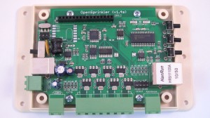
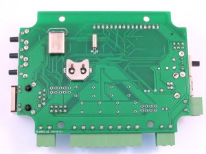
The images below are close-up views of the SMT version (front and back):

As you can see from the front image, most components are surface mount, except the peripheral components like screw terminals, connectors, buttons, and big capacitors. Two crystals and the button cell battery for RTC are on the back side. The SMT version uses the same software as the through-hole version, but it does have a few differences:

  • It has two extra analog pnis A6 and A7, which are accessible in Arduino programs.
  • The Ethernet connector is changed from SparkFun RJ45 jack to Hanrun 911105A, which is less expensive and more widely available.
  • There is a slide switch on the top-left corner of the PCB. This is used internally by us to switch between programming ATtiny45 and ATmega328. You should keep it in the ‘INT’ position.

Future Plans

To give you a heads-up, version 1.4 is likely to be the last one in this hardware generation, and will also be the last through-hole version. The next version OpenSprinkler 2.0 will be SMT only, and will switch to a completely different microcontroller in order to accommodate new features like better user interface, on-board wifi, logging, and more sensor options. However, the development of 2.0 will likely take more than a year, so it won’t be available until after summer next year (2013). Meanwhile, feel free to send me comments and suggestions on how to improve the OpenSprinkler functionality, and I will consider them for version 2.0!


Ok, this post is a bit late, as 1.3u has already started selling since Tuesday this week. Anyways, 1.3u is a minor revision since 1.2u. There are only a few changes (see Release Notes for details), so I didn’t make a release video. This post explains why these changes were made and some of the technical details.

  1. Added shift register OE (output enable) line
  2. This is mainly to address an issue with 74HC595 shift register that on powering up the output values are undefined. This can potentially lead to valves being randomly turned on for a short period of time before the mcu takes over and clears output values. It is not a huge issue, but quite annoying. It turns out that one simple solution is to add a control line to the 74HC595 OE (output enable) pin. This pin is active low, which means when set to low it enables output, and when set to high, it forces the output to be in high-impedance state, therefore the triacs will not turn on and the valves will remain closed.

    In 1.3u, Arduino digital pin 3 is assigned to control OE, and a pullup resistor is used to pull the pin high by default. On start-up, before the mcu takes over, OE is high, disabling output; then when the mcu completes initialization, it sets OE to low, enabling output. That’s it. Simple solution.

    Because of the added line, the extension board connector has been changed to 2×4 format (previously it was 2×3). If you own a previous version of OpenSprinkler and would like to use 1.3u extension board, you just need to solder a wire between the OE pin and Gnd , in order to enable output by default.

  3. TXD/RXD are now used as general I/O pins.

    This change was made to free up the A2 and A3 analog pins, since there have been many requests to make more analog pins available in order to connect external sensors like temperature and humidity sensors. Because TXD and RXD are now used as general I/O pins, they can no longer be used for Serial communication. In fact, since they are not used to control the LCD, calling Serial.begin() or Serial.print will cause the LCD to display garbage. If you need Serial communication, you can use the SoftSerial library which can simulate Serial communication on any pins.

  4. Added coin battery holder.

    Warning: this is a feature under development. It requires software support which is not available yet. The goal is to have a backup battery which allows the mcu to continue time keeping even when power is lost. Actually the easiest solution would be to just add a DS1307 Real-Time Clock (RTC). But my main hesitation is that DS1307 is quite pricy. Well, it’s not hugely expensive, but at $2 a piece (volume pricing), it is actually more expensive than the ATmega328 mcu. Isn’t that a bit silly? Anyways, the time keeping business can be well handled by the mcu itself. First, the mcu can run at a voltage as low as 1.8V, so when power is lost, it can continue running on a low-voltage battery; second, during power loss, the mcu will mostly be in sleep mode, using an external 32.768 kHz clock source, and occasionally waking up to update the time counter. This way, it can basically do whatever the RTC chip can do.

    The only tricky part is detecting power loss (which is already possible with the Power Sense pinout), and turning off peripheral components such as the Ethernet controller to minimize power consumption during sleep mode. These require some further experiments, which have been put on my todo list.

Another minor change is adding two resistors for the LEDs on the RJ45 Ethernet connector. In OpenSprinkler v1.1 and v1.0, the Ethernet connector did not have built-in LEDs. Then when I changed to use SparkFun’s RJ45 in v1.2, I forgot that it actually has built-in LEDs… So in this version the LEDs are wired in, which makes the circuit more complete 🙂

That’s all for OpenSprinkler v1.3u update. In case you are wondering about the frequent hardware changes, keep in mind that we are continually improving the design based on feedback and comments received from users. We run small batches (a couple hundred) for each version, that’s why we can have quick turn-around time in integrating new hardware features. At some point when the hardware becomes mature, we will make a surface mount version to improve the production throughput. Hopefully that point won’t be too far away!

I am glad to announce that the new interval program has been released and available for download at the OpenSprinkler GitHub page. This is a major software update since the initial release in October last year. Here is a list of new features in this version:

  • Program-based scheduling. Each program consists of a set of days (including weekdays, odd/even day restriction, and interval days), stations, start, ending, interval, and water time. The firmware supports up to 64 programs.
  • Choice of running stations either sequentially or concurrently.
  • Graphical Preview of each day’s program.
  • Integrated Manual Mode. When activated, the manual mode allows turning on or off stations using buttons on the homepage. An optional timer can be set to automatically shut stations off.
  • Support for rain sensor and location-based weather checking.

Details can be found in the video below, and the OpenSprinkler Instructions of Use page. This software version is compatible with all existing hardware versions, including v1.0, v1.1, and v1.2u. Feel free to give it a try. To find out how to re-program the MCU with new firmwares, please refer to the Re-programming Instructions. From now onw, the new interval program will replace the previous svc_full_schedule program, and become the default program shipped with all pre-flashed MCUs.


Technical Details

You will find that the new program has significantly improved the web user interface. This is made possible by using external Javascripts. As I described in a previous post, a major challenge in designing full-featured web interface is the limited program memory (flash) size of the ATmega328 MCU. The trick to get around with this limitation is by using external Javascripts stored on remote servers to ‘beautify’ the webpages. When you access the OpenSprinkler webpage in a browser, two pieces of information are combined in the browser: one is the essential data provided by the controller, the other is the set of Javascripts used to format webpages. The process to combine the two actually happens in your browser, which can interpret and execute complex Javascripts. This is called Client-Side processing. In addition to releasing the MCU from carrying the heavy ‘formattting’ code, another advantage of this separation is that you can easily replace the Javascripts to present data in a different format. This is in a sense similar to web Templates. Finally, debugging Javascripts is also a lot faster and easier than debugging microcontroller code, because it requires no re-flashing of the MCU, and most modern browsers support checking and error reporting of Javascript code.

One downside with this approach is that the Javascripts must be placed on a server that’s constantly available. Currently the scripts are stored on the Rayshobby web server, which is quite reliable. The path to the scripts is:
http://rayshobby.net/scripts/java/svc1.6/
There are 7 scripts involved: home.js, progmode.js viewoptions.js, viewprog.js, plotprog.js, modprog.js, manualmode.js. These are used to format various pages, including the homepage, program modification page, program preview page etc. However, if you ever want to customize the Javascripts yourself, you need to make a copy of these scripts and put them on your home server, a cloud server, or any file hosting server that can provide direct file access links. Note that the Javascript files are simply text files that store (human-readable) Javascript code. So any server that can host a text file is ok. If you decide to direct the scripts to your own server, simply modify JAVASCRIPT_PATH macro defined at the beginning of interval_program.pde, and point it to your new path.

You don’t have to worry about the security of using scripts stored on the Rayshobby server. Remember, in client-side processing, your controller data is never sent to the server; rather, it is sent to the browser that you are using to view the webpages. The browser will then retrieve the Javascripts and combine them with the data to present the webpages. Clearly there is no way we can ‘log’ your data or keep a record of your data, so it’s safe.

The Weather feature you saw in the demo video above is implemented using a Python script and Google Weather API installed on the Rayshobby server. This is an example of Server-Side processing, because the Python script runs on the server and not in your browser. The reason this requires server-side processing is because first, the Google Weather API returns fairly long XML data that cannot be directly parsed by the MCU, second, the MCU needs to periodically retrieve weather data, so it needs to initiate requests on its own and cannot rely on the existance of a web browser. Thus the Python script serves as a mechanism to convert complex XML data to microcontroller-readable format, and since it runs on the server, the microcontroller can send requests to it at any time.

OK, so much for the technical details. There is no way to cover all details in a single post. If you want to find out more about how the software works, please refer to the source code, or post a message on the forum.

« Newer Posts - Older Posts »