The Design
 For the water valve, I picked the Orbit yard watering valve. It’s widely available in home improvement stores, and it is cheap. It has two pins: applying +24v opens the valve, and -24v closes the valve. It uses a latch solenoid, drawing power only when you open or close it. This makes it very power efficient.
To use a single li-poly battery to drive the valve, I needed a voltage booster to raise the 3.6v provided by the battery to 24v momentarily before connecting to the valve solenoid. For this I chose an LT1303 DC/DC step-up converter, but any similar converter will do as well. Switching between applying +24v or -24v to the solenoid is achieved by using some MOSFETs. I can’t use small BJT transistors because they won’t handle the large impulse current through the solenoid (as high as 5A). Darlington transistor would work but I prefer MOSFETS for their power efficiency.
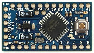 To program the valve, I use an Arduino pro mini. It’s adorably tiny and perfect for a mint tin project. I initially wanted to use the 3.3v/8Mhz version, as it can be directly powered by the 3.6v battery. But later I found that the wireless RF module only works with 5v anyways, so in the end I went with the 5v/16Mhz pro mini. This requires another voltage booster to raise the 3.6v battery to 5v. Fortunately I didn’t have to build another voltage booster for it; instead, I reused an existing minty boost which I soldered a while ago. I took off the tiny circuit board from it. Again, it fits cutely inside the space-limited mint tin.
The wireless module I used is an RF link 434MHz transmitter and receiver from SparkFun. They are small and easy to use. In particular, the receiver is quite thin and can sit comfortably along one side of the mint tin.
The schematic of the circuit is included below:

Parts List
- LT1303 DC/DC step-up converter
- AOP605 complementary MOSFETs (each contains 1 N-channel and 1 P-channel)
- 2N2222 BJT transistor
- 1N5817 and 1N4001 diodes
- RF link 434MHz transmitter and receiver
- Li-poly rechargeable battery
- Various resistors, capacitors, and inductor as specified in the schematic.
- (note that the 2200uF capacitor C2 must be rated 25v or above)
The circuit directly draws power from the 3.6v battery. I use the Arduino pin 6 to control the shutdown pin of LT1303. This way, I turn on the voltage booster only when I need to open or close the valve. The voltage booster outputs roughly 24.4v.
Arduino pin 8 and 9 are used to control opening or closing of the solenoid. Both pins are set to low at start. Next, setting pin 8 to high causes +24v to apply on the solenoid, opening the valve; on the contrary, setting pin 9 to high causes -24v to apply, closing the valve. Don’t try to set both pins to high at the same time, as it may short the circuit and cause damage.
Both the Arduino and the RF receiver are powered by the 5v output from minty boost. The data pin of the RF receiver is connected to Arduino pin 9 (which supports PWM).
The PCB
I soldered the initial prototype on a perf board. I made a mistake in connecting the MOSFET IC pins. This produced a spark and instantly fried the IC. Well, careful playing with 24v. After fixing the issue, the circuit worked like a charm.
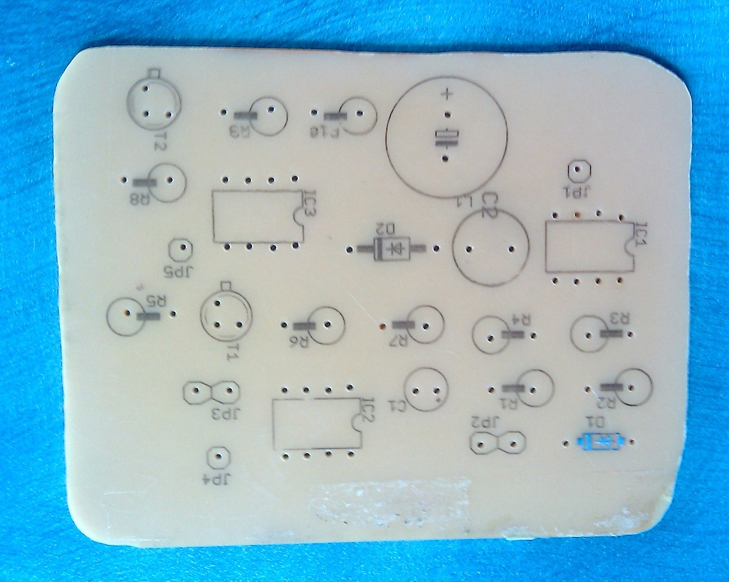
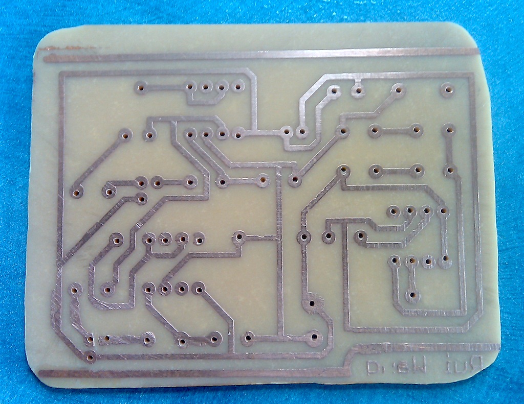
But the perf board looks a bit ugly and is too bulky for the mint tin, so I decided to design a custom PCB using Eagle CAD. This is the first PCB I’ve ever designed and made, so I felt quite a bit excited. I used the toner transfer method to produce the PCB. Playing with etching chemicals was not very pleasant. Here are two snapshots of the PCB:


Assembly
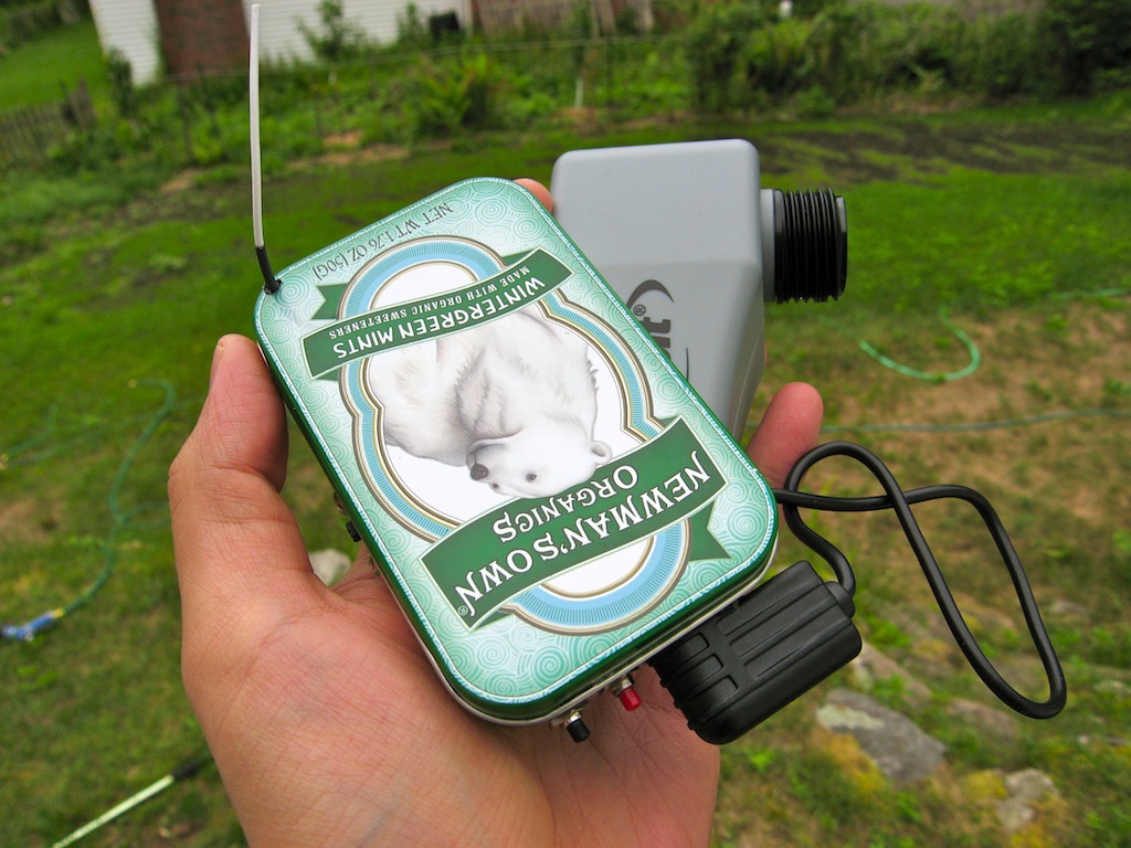
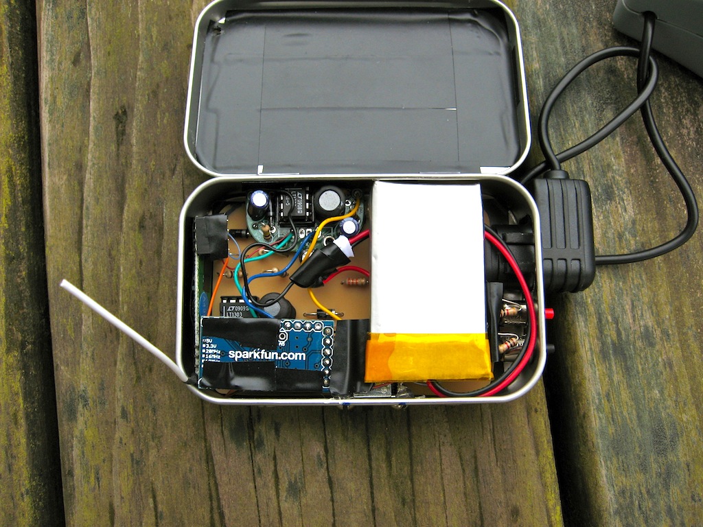
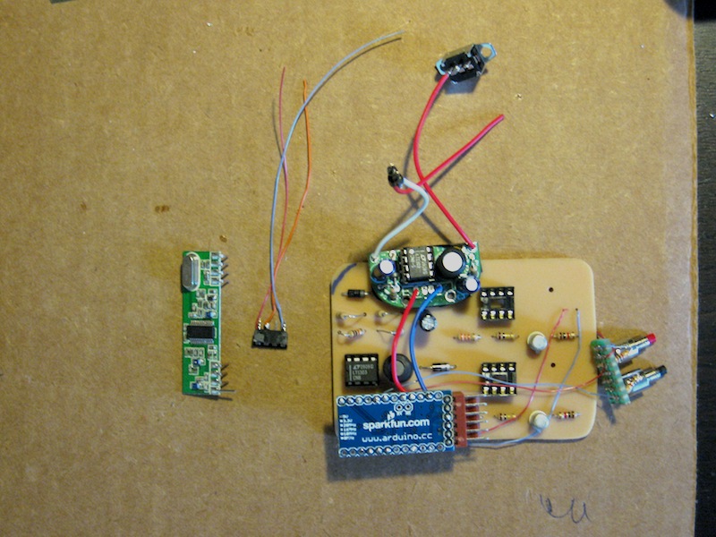
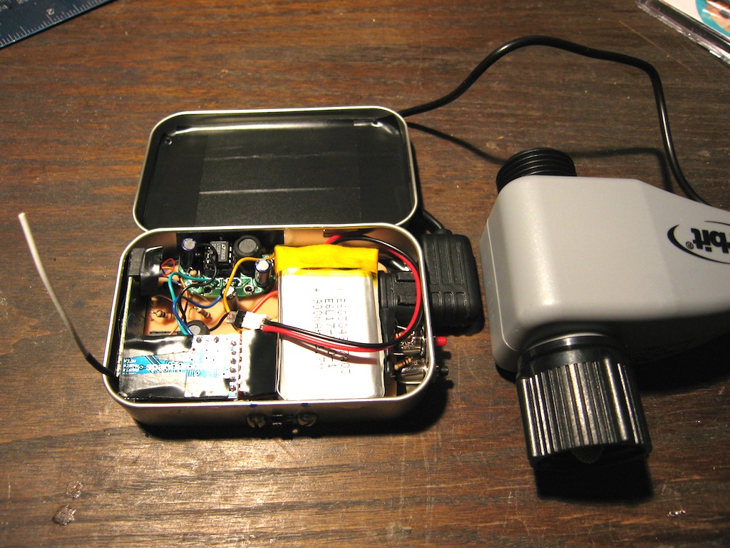
I picked some mint tin cans from Whole Foods. They have beautiful cover images. Assembling everything to the tin proved to be tricky than I thought: it’s not that I can’t fit everything, but because working with a bunch of wires and fixing buttons to the side of the can in such a small space made me feel like sowing embroidery. Tweezers are absolutely must-have tools. Also, I puts lots of electric tapes inside the tin and on various circuit parts to cover exposed area. You don’t want to accidentally short wires and cause trouble. Finally, I used hot glue sparingly to fix parts together. Below are snapshots of the parts before and after they are assembled into the tin:

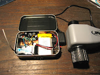 Additionally, I added a power switch on the front and two buttons on the right to allow for manual control of the valve. Everything packs neatly!
Here is an annotated snapshot showing where each part is located:

Testing
As the tin is not water-proof, I use a zipper plastic bag together with a paper clamp to seal it. I built a simple RF transmitter circuit on a breadboard to test the wireless control. It did work, but the range is currently limited to about 5 meters. I attribute this to the low voltage (3.6v battery) I used to power the transmitter. I am sure using 12v will increase the range a lot.
The whole circuit is reasonably power efficient. I’ve run it for two days and it is still working. The battery I use is a 900mAh rechargeable battery. A nice feature I would love to have in the future is to have it solar powered. This will completely eliminate the need to recharge the battery manually.
There are currently plenty of pins left on the Arduino unused. This provides some space to possibly control more valves using the same Arduino. But I am unsure if everything can still fit neatly in a mint tin anymore. Perhaps surface mounts are the way to go.
I haven’t programmed the Arduino to timer control the valve yet, but this should be straightforward. Some more advanced features can be included, such as installing a rain sensor to delay watering when it rains; or even better, use weather reports from online websites for intelligent watering! The wireless feature of the controller makes many options possible.
Code and Schematic Files
The Arduino code, Eagle CAD schematic/board files are attached below. Enjoy!
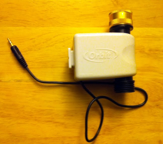
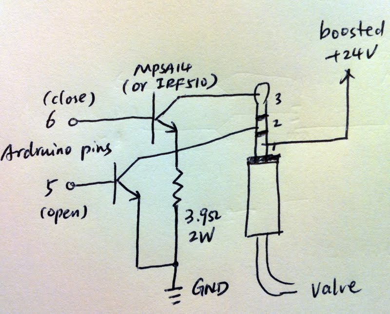
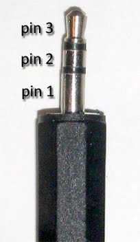 To figure out how to control the valve, my initial guess is that the valve contains two coils, one opens the solenoid and one closes it. To verify this, I measured the resistance between the 3 pins of the plug. It turns out that pin 1 and 2 have a 4.5 ohm resistance, while pin 1 and 3 have a 0.9 ohm resistance. The 4.5 ohm resistance is reasonable, as it’s roughly the same with the Orbit 91592 valve that I used previously. But the 0.9 ohm resistance is strange — it clearly indicates a coil but the resistance seems too lower.