Feed on
Posts
Comments

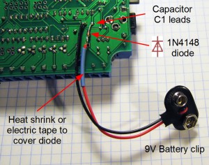
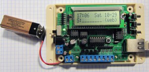
Matt asked about the option of having a backup battery for the OpenSprinkler, so I prepared a short blog article to show how it can be done. Basically, you just need to get a 9V battery (or any battery that can provide 6V or above voltage), connect the positive lead with a diode (such as 1N4148) in forward direction to the positive lead of C1 (100uF capacitor), and the battery’s negative lead to C1’s negative lead (which is ground). See pictures below for illustration. Make sure to use a heat shrink or electric tape to cover the diode after it’s soldered.

With the backup battery, the microcontroller (and hence the time) will keep running when there is power outage. Once the main power is back on and the Ethernet connection is available, the controller will be able to obtain more accurate time through NTP sync (the default setting is one sync per hour).

But there is a catch (as always!), which is: the controller draws a lot of current (~140mA), so with a standard 9V battery (the typical capacity of which is 560mAh) it can only last for about 4 hours.
The large current draw is mainly due to the Ethernet controller. One solution is to use a higher capacity battery (such as AA or Li-Poly). Another option is to put the Ethernet controller to sleep when it cannot get a connection. This can be done in software. In any case, there is now a temporary solution for battery backup, and a better option will be provided in the next hardware update.
Thanks for everyone who ordered the initial batch of the OpenSprinkler controller. A couple of issues have been reported and documented on the F.A.Q. page. If you are learning to use the controller, be sure to check that page.

The most recent bug turned out to be caused by the Arduino’s shiftOut function (thanks Matt for discovering the problem initially). This bug has now been reported to the Arduino forum. The symptom is that whenever you open the sprinkler zones, station #8 always turns on, and will remain on even if you stop the controller’s operation. This is caused by the shiftOut function missing a rising edge for the shift register. You can simply re-program the microcontroller to fix this bug. Orders sent on or after Oct 23, 2011 have already included this bug fix.

OpenSprinkler v1.0 Released

After several months of hard work, my first ‘serious’ Arduino-based electronics project is up on the project page now. Check out the OpenSprinkler – An Open-Source Sprinkler Valve Controller. This is a collaboration between me and Chris Anderson (editor-in-chief of Wired Magazine). A video demo is included below. For details and how to order a kit, please refer to the project page.

It has been a while since I updated my blog. Things have been quite crazy the past few months, but now I am back alive writing more blogs sparingly.

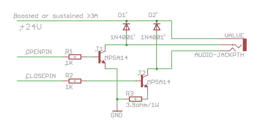
The first thing I want to share about is an update to my previous post that talked about how to control the Orbit 62035 valve. There have been a couple of missing pieces there which I would like to clarify. First, I found that a MOSFET cannot reliably control that valve. I am not sure why, but it may have to do with the on-state drain to source resistance. But using a MPSA14 (NPN darlington) works, and it requires a base current limiting resistor, so I’ve updated the schematic as below. Second, I was reminded that two kickback protecting diodes are needed to protect the transistor from the inductive current from the solenoid, so those are also added. These are the two main changes. The circuit below has been tested to work. Feel feel to leave comments.


Tags:

After finishing the previous minty water valve controller, I decided to make it an Arduino shield. This way, I can easily stack it onto other shields and extend its capability. I also added a few input buttons, and a DS1337 real-time clock, so that it can keep up with accurate time. Now the circuit has become much smaller, so I can’t produce it with home-made PCB any more(sadly…). Instead, I ordered professionally made PCBs from Laen, and here you are, meet the Arduino WaterValveShield!

PCB board:

Components soldered:

Close-up view:

Connected to a serial LCD display

The schematic:

You can download Eagle schematic and PCB design here. Feel free to use it and/or modify it, but be kind to give me some credit for it 🙂

Parts list with Mouser/Digi-key links: valve_shield_parts.zip 

As for sketch code, refer to my previous posts for code to control the valve and read input buttons. To interface with DS1337 RTC, I use this excellent RTC library.

Next steps:

Tags: ,

« Newer Posts - Older Posts »