Feed on
Posts
Comments
Update: check out the RFToy — an easy-to-use standalone gadget to control remote power sockets. Also, support for remote power sockets have been added to OpenSprinkler firmware 2.1.1.

In previous blog posts, I’ve described two ways to use an Arduino to interface with an off-the-shelf remote power sockets / switches. The first method uses transistors to simulate button presses. It involves some soldering and hacking the remote control unit. The second method uses an oscilloscope to sniff the signal sent by the remote control, and then simulates the same signal using an RF transmitter. But what if you don’t have an oscilloscope, or don’t know where to place the probe to take the measurement? In this post, I will describe a very simple method to sniff remote control signals. It only requires a 434 MHz RF receiver, a couple of resistors, an audio cable, a sound card (with line-in), and an free audio processing software. (Note: some RF remote sockets work at 315 MHz frequency range).

Update: check out the RFToy — an easy-to-use standalone gadget to control remote power sockets. Also, support for remote power sockets have been added to OpenSprinkler firmware 2.1.1.

To get started, I picked a set of indoor wireless power sockets from Amazon. This is different from the model I had before, and it’s not based on the PT2262 encoder, so I cannot predict the RF signal by just looking at the circuit board connections. The reason I picked this model is because it has separate On and Off buttons for each socket, instead of just a Toggle button. So if you want to make sure the socket is on, just repeatedly send the on signal. With only a toggle button, if there is a power reset or if the previous command was not successfully received, you will mess up the control and end up with completely flipped on/off status.


RF Sniffing Circuit

Ok, here is the fun part: how can we sniff the signals sent by the remote control to the sockets? It turns out that most of these remote controls work in the 434 MHz band (note: some work in 315 MHz), so we can use a cheap 434 MHz RF receiver to intercept the signal. To record the signal, a simple way is to use your sound card and an audio recording software. The sound card can digitally sample the signal at high speed (e.g. 48,000 Hz), and it can record a signal over a long time, so it is more convenient than using an oscilloscope.
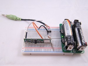
This is by no means a new idea. I found it when reading this forum post. Scroll down and you will see the schematic to make the sniffing circuit. One important thing is that you should plug the audio cable to the Line-In jack on your sound card, not the Mic jack.

The picture on the left is my implementation of the circuit. I used my handy AASaver to provide the +5V needed by the RF receiver. This way, the whole circuit sits on a breadboard without any external power adapter. I can easily insert it to the sound card at the back of my desktop PC.


Record the Control Signals

I used the open-source Audacity software in Linux to record the signals. All I have to do is to start recording, and press each of the 6 buttons on the remote control. Then I will zoom in and analyze the signals. Below is a snapshot:
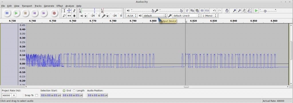
Basically when you press a button, the same sequence is sent multiple times. Each sequence consists of two types of square waves: a long on followed by a short off, which I call a ‘1’, and a short on followed by a long off, which I call a ‘0’.

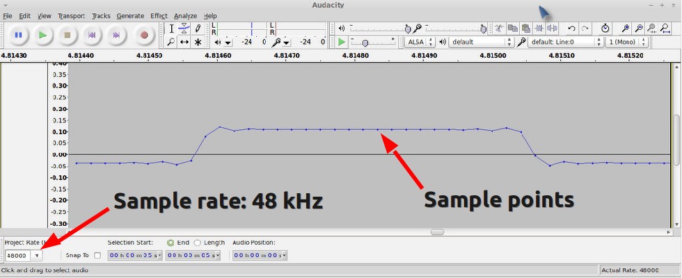
How can we find out the timing (i.e. the width) of the signal? In Audacity, if you zoom in the signal to the extreme, you will see the actual signal sample points. Remember that we know the sampling rate, which is 48000 Hz by default. So if we count the number of sample points, and divide that by the sampling frequency, then we will get the timing. For example, below is a snapshot of a short on. I counted that there are about 21 sample points, so the width of it (i.e. a short on or short off) is

Similarly, I figured out that a long on or long off is about 1300 us, which is three times the width of a short on or off. Also, there is about 12.5 ms delay before re-sending the same sequence. These timings don’t have to be very accurate.

With the timings figured out, I can now write down the complete sequence corresponding to each button:


Socket 1 on: 1001 0000 0010 1000 00000000000
Socket 1 off: 0101 0000 0010 1000 00000000000
Socket 2 on: 1001 0000 0010 0100 00000000000
Socket 2 off: 0101 0000 0010 0100 00000000000
Socket 3 on: 1001 0000 0010 0010 00000000000
Socket 3 off: 0101 0000 0010 0010 00000000000

Each ‘1’ is a 433 us on followed by a 1300 us off, and each ‘0’ is a 1300 us on followed by a 433 us off. The first 4 bits indicate socket on/off, the next 8 bits are always the same, and the 4 bits following from that indicate the index of each socket.

With these patterns recorded, I can reproduce the signal using an Arduino and a 434 MHz RF transmitter. The RF transmitter has one data pin, which can be connected to any Arduino I/O pin. Since there is a little bit of overhead when using Arduino’s delayMicroseconds function, I reduced the short delay time to 410 us. This way, the signal generated by the code is almost identical to the that produced by the remote control.

Download
  • Download example Arduino code here. This example program assumes the RF transmitter data pin is connected to Arduino pin D3, which you can change at the beginning of the file.


Use OpenSprinkler to Control Power Sockets

Now that my Arduino can talk to the remote power sockets, how about adding Internet-based control? For example, sending control signals through a web interface, or even setting a time schedule to turn on or turn off sockets automatically during a day? Aha, my OpenSprinkler is perfect for this purpose. There are two reasons, first, the OpenSprinkler is an integrated circuit that includes ATmega328 + Ethernet + LCD + USB programmer; second, the latest OpenSprinkler software provides a nice web interface where you can set an interval schedule or switch to manual control mode. All that I have to do is to connect the RF transmitter using one of the available pins on board, and then add a few lines of code to send the RF signal wherever the corresponding sprinkler station is turned on or off. This way, I can easily use the same web interface to control power sockets. Internet of things instantly!

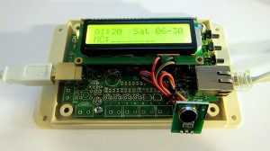
The image above shows my implementation. I used a half-built OpenSprinkler, with everything except the switching regulator section and the solenoid driver section. The RF transmitter is connected to the controller using three wires. Again, one of the nice things is that I can directly use the software already written for OpenSprinkler, to set a time schedule for automatically turning on or off power sockets. In addition, I can switch to manual control mode, which also has built-in timers.

What’s Next?

My next plan is to use the sniffing circuit to reverse engineer RF signals sent from wireless temperature, humidity, and rain sensors. This will allow me to use an Arduino and a RF receiver to decode the wireless data and get local temperature, humidity, and rain information. Of course the tricky part is to figure out how the data is encoded. So I will have a couple of posts in the next week or so about RF hacking. Stay tuned!
Update: check out the RFToy — an easy-to-use standalone gadget to control remote power sockets. Also, support for remote power sockets have been added to OpenSprinkler firmware 2.1.1.

Note: the RF transmitter used in this article is available for purchase in the shop page.

In a previous post I described a way to use an Arduino to interface with remote controlled power sockets. The idea was to make use of the original remote control, and a high-side transistor switch to simulate button presses. This approach is generic: you don’t need to know how the remote control signal is encoded, instead, just treat the remote control as a black box and simulate the button presses. However, the downside of this approach is that it requires soldering wires and components to the remote control, which is quite a bit of work.

Update: check out the RFToy — an easy-to-use standalone gadget to control remote power sockets. Also, support for remote power sockets have been added to OpenSprinkler firmware 2.1.1.

Recently, inspired by the JeeLabs KAKU remote switch article, I figured out a new way to interface with these remote power switches. The method published by JeeLabs uses an RFM12B transceiver, which is cool because my OpenSprinkler design has a reserved spot for RFM12B. Unfortunately after many experiments I was unable to get it to work with my switches. However, I did succeed by using a 433MHz RF transmitter purchased from SparkFun. So below I document the process of how I did it.

To begin, I took apart the remote control. The goal is to reverse engineering the signal sent from the remote control, so that I can use an Arduino to simulate the same signal. This will allow me to use a program to control the power sockets. The schematic of the remote control circuit can be found in the previous post. Basically it consists of an encoder IC (HT2262 or PT2262) and a 433MHz RF transmitter circuit.

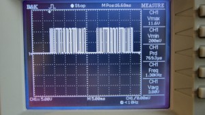
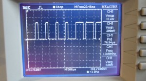
By connecting an oscilloscope to the circuit I was able to analyze the signal patterns. Details can be found in the video attached at the end of this post. Below are the patterns I observed when button 1 is pressed (corresponding to power socket 1).

The signal consists of two basic patterns: a short HIGH followed by a long LOW, which I call a ‘0’ all together, and a long HIGH followed by a short LOW, which I call ‘1’. The long part is roughly 500us and the short part is roughly 160us (so it’s about a 3:1 ratio). Each signal sequence consists of 25 bits: the first 16 bits are always ‘0000 1111 0101 0101’, which I call the ‘signature’; and the next 8 bits are the ‘command’, which correspond to the index of the power socket; finally, there is always an ending ‘0’.

For example, the entire sequence to toggle socket 1 is

0000 1111 0101 0101 1100 0001 0

the entire sequence for socket 2 is:

0000 1111 0101 0101 0011 0001 0

and for socket 3 it is:

0000 1111 0101 0101 0000 1101 0

Again, a ‘1’ means a 500us HIGH followed by a 160us LOW, and a ‘0’ means a 160us HIGH followed by a 500us LOW. When a button is pressed, the sequence is repeated several times, for robustness I guess.

Interestingly, you can OR the command part in order to toggle two or three sockets at the same time. For example, the sequence below will simultaneously toggle socket 1 and 2:

0000 1111 0101 0101 1111 0001 0

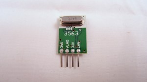
Next, to simulate the remote control signal using an Arduino, I used a 434MHz RF transmitter from SparkFun. This transmitter has only 4 pins: Gnd, Vcc, Antenna, and Data. The data pin can be connected to any digital pin on the Arduino in order to send the control sequence as analyzed above.

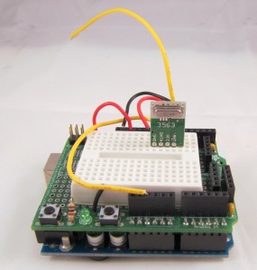
For demonstration, I used Arduino pin 10 to send the control sequence through the Data pin. The connection is as follows: VCC->+5V, GND->GND, DATA->Digital 10, ANT->a short wire. The supply voltage for the RF transmitter can be anywhere between 1.5V to 12V. The higher the voltage, the longer the transmission range. Normally 5V should be good for at least 15-20 meters. If you want the highest range, use a +12V power adapter to power your Arduino, and connect the RF transmitter Vcc pin to the Arduino VIN pin. Alternatively, you can add a voltage boost converter to bump +5V to +12V.

Below you can download the Arduino program I wrote. The code should be easy to follow.

If you have a different remote controlled power switch, you can follow the same procedure to find out the control sequence, then modify the program accordingly. A video demo is provided below:

Credits: the method is based on JeeLabs KAKU remote switch and the code is based on the kaku_demo sketch included in their RF12 Arduino library.

Note: the RF transmitter (434MHz) is available for purchase in the shop page.


Update 1: apparently if you look at the datasheet of PT2262, which I found a copy here, it explains how the encoding pattern is computed. The ‘signature’ part has to do with the status of each pin from A0 to A7 on PT2262 – whether the pin is connected to GND, VCC, or floating, and the ‘command’ part is determined by the status of each pin from D0 to D3. I compared the circuit with the datasheet and verified that the pattern I observed from the oscilloscope matches the calculation. Also, according to the datasheet and the resistor value I found on the remote control, it looks like the long delay should be about 400us and short delay 133us, which is a bit different from the 500us and 160us observed from the oscilloscope. Also, the ending ‘0’ in my sequence turns out to be a ‘sync’ bit, which is 133us high followed by 4200us low. The fact that my original sketch has worked means there is a some level of tolerance in the timings. So they do not have to be highly accurate.

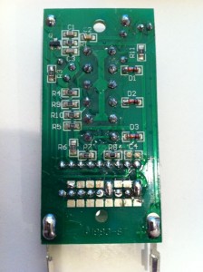
Update 2: new version of remote control. A reader of this post, Chuck, sent me a question that the sketch doesn’t seem to work with his remote control. After researching this issue, we found that the new version of the remote has changed to use SMT components and also has changed the coding pattern. Chuck sent me an image of the back of the PCB. From the image and the datasheet of PT2262, I figured out the new coding pattern. Basically, the ‘signature’ part of the code has been changed from

0000 1111 0101 0101

to

1101 0111 0101 0101

More technically, the coding pattern can be derived from the connections of Pins 0-7 of PT2262. In the newer version (from the PCB image on the left), the first 4 pins are connected as HIGH, FLOAT, FLOAT, HIGH, whereas the older version is connected as LOW, LOW, HIGH, HIGH. Here HIGH means connected to Vcc, LOW means connected to Ground, FLOAT means unconnected. Taking a look at the datasheet, you can easily figure out the actual code: LOW -> 00, HIGH -> 11, FLOAT: 01.

Chuck sent me his modified code, which you can download here.


Update: check out the RFToy — an easy-to-use standalone gadget to control remote power sockets. Also, support for remote power sockets have been added to OpenSprinkler firmware 2.1.1.

For a while I’ve been looking for a way to switch household power line (110V) devices. One of the simplest options is to use a relay that is connected to the power line. This is easy in concept but quite dangerous to work with. You don’t want to accidentally touch the power line wire and shock yourself. A much better option is to use the powerswitch tail, which insulates the relay and the relevant circuity inside a plastic enclosure, leaving only two MCU pins to interface with. Much safer. But you still have to run wires between your MCU and the power socket. I am more interested in an wireless option.

Recently I purchase a set of remote controlled switch sockets from Amazon. It comes with one remote and three sockets, each of which can be individually switched. The whole package is quite cheap. The way this works is that you plug the sockets into the wall, and when you press a button on the remote, the corresponding socket will switch, thus turning on or off the device connected to the socket.

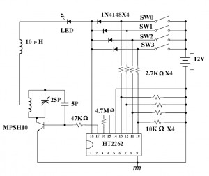
I took apart the remote control and found that the circuit is quite simple. It’s based on an HT2262 remote control encoder and a 434 MHz transmitter circuit. In fact, the schematic of the circuit is well documented in the datasheet of the encoder:

From the schematic, it’s quite clear that when a button is pressed, the input voltage is fed to one of the encoder pins (as well as the VCC pin of the encoder). Then the encoder will send the signal to the RF transmitter circuit. The RF signal will be received at the power socket side and decoded. Very simple. Now, to use my Arduino to interface with this power switch, all I need to do is to simulate a button press by sourcing a positive voltage to wires labeled SW1, SW2, SW3 etc. It turns out that the HT2262 can work with a fairly wide range of voltage: from 4V to 18V. Clearly the 5V output from an Arduino IO pin falls within the acceptable range. So I can simply connect those wires individually with Arduino I/O pins, and write a program that outputs HIGH momentarily when I need to switch a device. The only downside is at 5V the transmitting range is limited. The higher the input voltage, the longer distance it can transmit. So a more flexible design is to have a ‘source’ driver to supply higher than 5V to the encoder.

Update: check out the RFToy — an easy-to-use standalone gadget to control remote power sockets. Also, support for remote power sockets have been added to OpenSprinkler firmware 2.1.1.

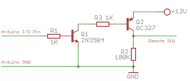
This can be done by using a transistor based high-side switch. Here is a schematic:

Basically, when the IO pin outputs low, transistor Q1 (NPN) turns off, and its collector is in high impedance status. Hence Q2 (PNP) is also off. Now, when the IO pin outputs high, Q1 conducts, driving the gate of Q2 low. Therefore Q2 also conducts, sourcing +12V voltage to the encoder. The reason to use such a high-side driver is to be able to switch a high voltage (>=12V) using a relatively low-voltage (<=5V) control signal from the MCU.

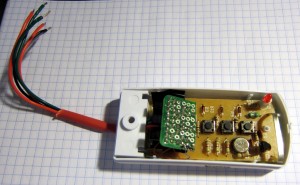
I implemented this method on a small proto-board. Since the remote control has 3 buttons, I made 3 copies of the above high-side driver, and the entire circuit fits nicely inside the remote control cover. I soldered five wires out: +12V, GND, and three control wires. A picture is shown on the left.

With this modification, I can now switch power line devices such as home lights and heaters using a microcontroller. Better, I can connect the remote control with my OpenSprinkler Controller, thus I am able to control power line devices through a web interface. The video below show a demo. Enjoy!

« Newer Posts