During the process of cleaning up my workshop today, I collected all the OpenSprinkler prototype boards that have had design mistakes or were built and failed in the past, and looks at this whole box of lovely PCBs:
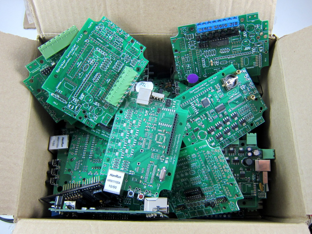
Probably no less than 30 boards in the box. It’s quite shocking to realize how many there are. By far getting prototype PCBs has been the most time-consuming and costly part of the development process. First of all, each round of prototype PCBs costs about $50 and takes 9 to 12 days of lead time (using the fastest shipping option), from places like SeeedStudio or Smart-Prototyping. The cost is not dramatic, but the lead time is quite significant unless if I am willing to pay hundreds of dollars to order from US-based services. Also, these boards are unfortunately complex enough that home DIY PCBs are no longer a viable solution.
Then, no matter how careful I am in designing the PCB, there are always a couple of unforeseen issues that had to be discovered when I actually start assembling. For example, a component might be too far away from the enclosure cutout, a component footprint might be wrong, two components might be too close to each other, the pin headers were placed in the wrong orientation, and sometimes I forget to add a ground plane. Because these issues are only discovered after one round of PCBs have arrived (then I will fix the issues, refine the design, and order another round), they make the development process sequential and cause the overall time and cost to quickly add up. The good thing is that over time I learn from lessons and accumulate tips to help me maximally avoid potential mistakes. Still, it’s inevitable to produce design issues, which can only be fixed by putting in more money and time.
When I get the finalized PCB, however, I often feel proud, as if it’s a work of art which has been refined and polished and is ready to be seen by the public. Then I get a sense of achievement. That’s the joy of working on electronic circuits 🙂