Feed on
Posts
Comments
Update: check out the RFToy — an easy-to-use standalone gadget to control remote power sockets. Also, support for remote power sockets have been added to OpenSprinkler firmware 2.1.1.

For a while I’ve been looking for a way to switch household power line (110V) devices. One of the simplest options is to use a relay that is connected to the power line. This is easy in concept but quite dangerous to work with. You don’t want to accidentally touch the power line wire and shock yourself. A much better option is to use the powerswitch tail, which insulates the relay and the relevant circuity inside a plastic enclosure, leaving only two MCU pins to interface with. Much safer. But you still have to run wires between your MCU and the power socket. I am more interested in an wireless option.

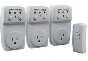
Recently I purchase a set of remote controlled switch sockets from Amazon. It comes with one remote and three sockets, each of which can be individually switched. The whole package is quite cheap. The way this works is that you plug the sockets into the wall, and when you press a button on the remote, the corresponding socket will switch, thus turning on or off the device connected to the socket.

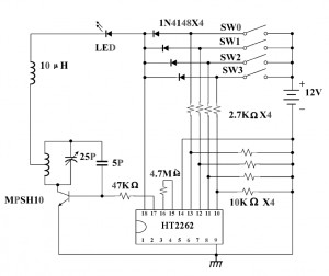
I took apart the remote control and found that the circuit is quite simple. It’s based on an HT2262 remote control encoder and a 434 MHz transmitter circuit. In fact, the schematic of the circuit is well documented in the datasheet of the encoder:

From the schematic, it’s quite clear that when a button is pressed, the input voltage is fed to one of the encoder pins (as well as the VCC pin of the encoder). Then the encoder will send the signal to the RF transmitter circuit. The RF signal will be received at the power socket side and decoded. Very simple. Now, to use my Arduino to interface with this power switch, all I need to do is to simulate a button press by sourcing a positive voltage to wires labeled SW1, SW2, SW3 etc. It turns out that the HT2262 can work with a fairly wide range of voltage: from 4V to 18V. Clearly the 5V output from an Arduino IO pin falls within the acceptable range. So I can simply connect those wires individually with Arduino I/O pins, and write a program that outputs HIGH momentarily when I need to switch a device. The only downside is at 5V the transmitting range is limited. The higher the input voltage, the longer distance it can transmit. So a more flexible design is to have a ‘source’ driver to supply higher than 5V to the encoder.

Update: check out the RFToy — an easy-to-use standalone gadget to control remote power sockets. Also, support for remote power sockets have been added to OpenSprinkler firmware 2.1.1.

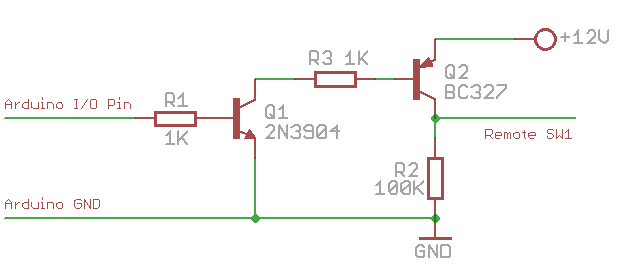
This can be done by using a transistor based high-side switch. Here is a schematic:

Basically, when the IO pin outputs low, transistor Q1 (NPN) turns off, and its collector is in high impedance status. Hence Q2 (PNP) is also off. Now, when the IO pin outputs high, Q1 conducts, driving the gate of Q2 low. Therefore Q2 also conducts, sourcing +12V voltage to the encoder. The reason to use such a high-side driver is to be able to switch a high voltage (>=12V) using a relatively low-voltage (<=5V) control signal from the MCU.

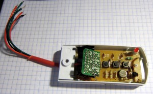
I implemented this method on a small proto-board. Since the remote control has 3 buttons, I made 3 copies of the above high-side driver, and the entire circuit fits nicely inside the remote control cover. I soldered five wires out: +12V, GND, and three control wires. A picture is shown on the left.

With this modification, I can now switch power line devices such as home lights and heaters using a microcontroller. Better, I can connect the remote control with my OpenSprinkler Controller, thus I am able to control power line devices through a web interface. The video below show a demo. Enjoy!

Recently I was looking for a cheap 16×2 LCD, and I found several interesting models on eBay that come with great price. I purchased one with blue backlight. The total is only $3.49 including shipping. The product was shipped from Hong Kong, so it took about 2 weeks to arrive. Here are two images of the front and the back:

The model number is 1602a and the spec is easy to find online by searching the model number. It’s HD44780 compatible, so it can work directly with the Arduino LiquidCrystal library. The blue LED backlight looks quite pleasant. Here is an example:

One downside is that the back LED is a bit noticeable (see the glow on the right edge of the display); also, the text will be almost completely invisible if the LED is turned off, so the LED has to remain on, consuming more power.

Making it work with Arduino is straightforward by following the LiquidCrystal example. I made small changes to the pin assignment. Here is what I did: LCD RS, Enable, D4, D5, D5, D6 pins are connected to Arduino pin 12, 11, 8, 7, 6, 5 respectively. Normally the display contrast (V0) pin of the LCD is connected to a potentiometer in order to adjust the contrast voltage. After some experiment, I found that the desirable voltage is about 0.65V, which can be supplied by the forward bias voltage of a standard diode, such as 1N4148.

In order to control the back LED brightness, I made use of a transistor (2N3904) and Arduino’s PWM (pulse width modulation) to adjust the effective voltage supplied to the LED. The transistor serves as a current sink, and its base is connected to Arduino pin 10 to apply PWM control. This is very standard design, refer to the schematic below. With this, I can easily control the brightness of the backlight. Just to demonstrate it, I wrote a simple program based on the Scroll example provided in Arduino. The program scrolls text left and right, meanwhile I use a timer interrupt to brighten and dim the backlight. See the video below.

Some ghosting artifacts are noticeable as the words move left and right. The video probably exemplified them, the actual LCD looks better than the video.

Update: It’s ok to connect Arduino pin 10 directly with LED- or LED+ to supply the PWM signal without using a transistor. Arduino’s I/O pins can source or sink more than 20mA of current, which is sufficient to drive the backlight LED. Other microcontrollers might not be able to do so directly from their I/O pins.

In summary, this is an decent and inexpensive LCD, which works nicely with Arduino. Right now it occupies 7 Arduino pins (1 of them has to support PWM), but this number can be reduced to 3 by using a shift register. The schematic and source code for the example program are attached below. Comments and suggestions are welcome!

Download Arduino source code lcd1602a.pde.


Tags: , ,

A New Home for Blog

After being silent for a long time, I decided to resume my blog, and as a new start, I have moved my blog from Google blog to hosted WordPress. One reason for the move is that I plan to expand the blog into a more full-featured website in the near future; the other reason is that Google blog feels very sluggish for viewing (i.e. scrolling up and down), and WordPress is much faster. I was happy to find that WordPress can import Google Blogger posts (together with comments). This way I feel I didn’t lose the history. Some new projects will be coming up soon. Stay tuned!

WordPress icon

As described in my previous blog about the first-time experience with the Makerbot, we encountered a problem where the extruder motor would stop moving after a while. Apparently there have been many discussions about this issue, such as here, here, and here. It seems to be generally agreed that the problem originated from the suboptimal performance of the extruder motor, particularly that its resistance can drop to close to 0 during operation, causing an overload current that fails the H-bridge (A3949) on the extruder controller board. I tried connecting a small power resistor in series with the motor and it still failed after a while.

The most commonly used solution seems to be the relay fix by rwensley. This allows the extruder motor to be powered directly from the +12V supply line, avoiding the failure of A3949. But the downside of a relay fix is that PWM is disabled, thus the feed speed cannot be fully controlled. So I started thinking about a MOSFET based fix. The first version is to use a single MOSFET (IRF510) in the place of relay, and this allows the motor to only move forward (which often suffices). The schematic is shown below:

The 1K resistor R1 is a pull-down resistor (1/4W is sufficient). Its value turns out to be important, because the on-board A3949 H-bridge seems to have a pull-up resistor of about 70K. Thus even when the H-bridge is inactive, the motor ports (1A and 1B) are pulled up to +12V, which must be pulled down to well below 2V in order for Q1 (IRF510) to remain off. The 1K value works perfectly (if the value is too large, it won’t be able to pull the voltage low enough). The reason IRF510 works is because it allows a high current (20A pulsed) to pass through it, which is much larger than what the A3949 chip can handle.

Using MOSFET, the main benefit is that the PWM works, hence the motor feed speed can be controlled and tuned in order to print out fine details of a 3D model. I was able to print several models with great details that I wasn’t able to achieve when PWM had to be fixed to 255 all the time.

After the single MOSFET solution worked, I started thinking how to make the motor move backward as well. It looked like the simplest way is to reproduce an H-bridge using 4 MOSFETs. The schematic is shown below:

It’s basically one of the standard H-bridge implementations. Q1 and Q4 are N-channel MOSFETs and should use IRF510 or any alternative(STP16NF06, RFP30N06LE etc.) that supports at least 10A drain-source current; Q2 and Q5 are similar but P-channel, and should use IRF9530 or any suitable alternative (STP12PF06, FQP27P06 etc.)

Note that there is no special mechanism here to handle shoot-through, which is a known issue for H-bridge design. But in this case, even if shoot-through happens, it will be over a very short period of time, and the MOSFETs are able to handle a high impulse current if that happens. I’ve tested the circuit in continuously printing for several hours and have not encountered any problem. Also note that the kickback protection diodes are ignored as the MOSFETs already have built-in diodes. Here is the small protoboard with all components soldered on it:

With this fix, the extruder motor can now move forward and backward, and PWM works in both directions! I’ve seen in several places that eventually the extruder motor should use a stepper as it provides much better control. But before that happens, I am sticking with my fix for now.

Tags: , ,

I tried to print out a scanned angel model. The details are a bit weak given the Makerbot’s resolution. But it makes a nice decoration for the bot.

Two additional photos:

Tags:

« Newer Posts - Older Posts »