Feed on
Posts
Comments
Update: check out the RFToy — an easy-to-use standalone gadget to control remote power sockets. Also, support for remote power sockets have been added to OpenSprinkler firmware 2.1.1.

In previous blog posts, I’ve described two ways to use an Arduino to interface with an off-the-shelf remote power sockets / switches. The first method uses transistors to simulate button presses. It involves some soldering and hacking the remote control unit. The second method uses an oscilloscope to sniff the signal sent by the remote control, and then simulates the same signal using an RF transmitter. But what if you don’t have an oscilloscope, or don’t know where to place the probe to take the measurement? In this post, I will describe a very simple method to sniff remote control signals. It only requires a 434 MHz RF receiver, a couple of resistors, an audio cable, a sound card (with line-in), and an free audio processing software. (Note: some RF remote sockets work at 315 MHz frequency range).

Update: check out the RFToy — an easy-to-use standalone gadget to control remote power sockets. Also, support for remote power sockets have been added to OpenSprinkler firmware 2.1.1.

To get started, I picked a set of indoor wireless power sockets from Amazon. This is different from the model I had before, and it’s not based on the PT2262 encoder, so I cannot predict the RF signal by just looking at the circuit board connections. The reason I picked this model is because it has separate On and Off buttons for each socket, instead of just a Toggle button. So if you want to make sure the socket is on, just repeatedly send the on signal. With only a toggle button, if there is a power reset or if the previous command was not successfully received, you will mess up the control and end up with completely flipped on/off status.


RF Sniffing Circuit

Ok, here is the fun part: how can we sniff the signals sent by the remote control to the sockets? It turns out that most of these remote controls work in the 434 MHz band (note: some work in 315 MHz), so we can use a cheap 434 MHz RF receiver to intercept the signal. To record the signal, a simple way is to use your sound card and an audio recording software. The sound card can digitally sample the signal at high speed (e.g. 48,000 Hz), and it can record a signal over a long time, so it is more convenient than using an oscilloscope.
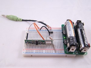
This is by no means a new idea. I found it when reading this forum post. Scroll down and you will see the schematic to make the sniffing circuit. One important thing is that you should plug the audio cable to the Line-In jack on your sound card, not the Mic jack.

The picture on the left is my implementation of the circuit. I used my handy AASaver to provide the +5V needed by the RF receiver. This way, the whole circuit sits on a breadboard without any external power adapter. I can easily insert it to the sound card at the back of my desktop PC.


Record the Control Signals

I used the open-source Audacity software in Linux to record the signals. All I have to do is to start recording, and press each of the 6 buttons on the remote control. Then I will zoom in and analyze the signals. Below is a snapshot:
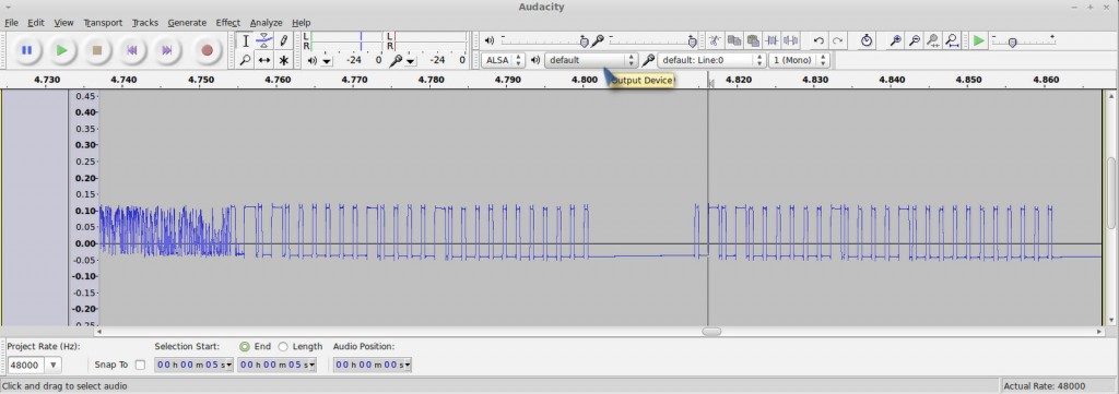
Basically when you press a button, the same sequence is sent multiple times. Each sequence consists of two types of square waves: a long on followed by a short off, which I call a ‘1’, and a short on followed by a long off, which I call a ‘0’.

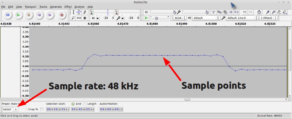
How can we find out the timing (i.e. the width) of the signal? In Audacity, if you zoom in the signal to the extreme, you will see the actual signal sample points. Remember that we know the sampling rate, which is 48000 Hz by default. So if we count the number of sample points, and divide that by the sampling frequency, then we will get the timing. For example, below is a snapshot of a short on. I counted that there are about 21 sample points, so the width of it (i.e. a short on or short off) is

Similarly, I figured out that a long on or long off is about 1300 us, which is three times the width of a short on or off. Also, there is about 12.5 ms delay before re-sending the same sequence. These timings don’t have to be very accurate.

With the timings figured out, I can now write down the complete sequence corresponding to each button:


Socket 1 on: 1001 0000 0010 1000 00000000000
Socket 1 off: 0101 0000 0010 1000 00000000000
Socket 2 on: 1001 0000 0010 0100 00000000000
Socket 2 off: 0101 0000 0010 0100 00000000000
Socket 3 on: 1001 0000 0010 0010 00000000000
Socket 3 off: 0101 0000 0010 0010 00000000000

Each ‘1’ is a 433 us on followed by a 1300 us off, and each ‘0’ is a 1300 us on followed by a 433 us off. The first 4 bits indicate socket on/off, the next 8 bits are always the same, and the 4 bits following from that indicate the index of each socket.

With these patterns recorded, I can reproduce the signal using an Arduino and a 434 MHz RF transmitter. The RF transmitter has one data pin, which can be connected to any Arduino I/O pin. Since there is a little bit of overhead when using Arduino’s delayMicroseconds function, I reduced the short delay time to 410 us. This way, the signal generated by the code is almost identical to the that produced by the remote control.

Download
  • Download example Arduino code here. This example program assumes the RF transmitter data pin is connected to Arduino pin D3, which you can change at the beginning of the file.


Use OpenSprinkler to Control Power Sockets

Now that my Arduino can talk to the remote power sockets, how about adding Internet-based control? For example, sending control signals through a web interface, or even setting a time schedule to turn on or turn off sockets automatically during a day? Aha, my OpenSprinkler is perfect for this purpose. There are two reasons, first, the OpenSprinkler is an integrated circuit that includes ATmega328 + Ethernet + LCD + USB programmer; second, the latest OpenSprinkler software provides a nice web interface where you can set an interval schedule or switch to manual control mode. All that I have to do is to connect the RF transmitter using one of the available pins on board, and then add a few lines of code to send the RF signal wherever the corresponding sprinkler station is turned on or off. This way, I can easily use the same web interface to control power sockets. Internet of things instantly!

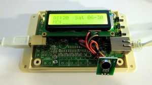
The image above shows my implementation. I used a half-built OpenSprinkler, with everything except the switching regulator section and the solenoid driver section. The RF transmitter is connected to the controller using three wires. Again, one of the nice things is that I can directly use the software already written for OpenSprinkler, to set a time schedule for automatically turning on or off power sockets. In addition, I can switch to manual control mode, which also has built-in timers.

What’s Next?

My next plan is to use the sniffing circuit to reverse engineer RF signals sent from wireless temperature, humidity, and rain sensors. This will allow me to use an Arduino and a RF receiver to decode the wireless data and get local temperature, humidity, and rain information. Of course the tricky part is to figure out how the data is encoded. So I will have a couple of posts in the next week or so about RF hacking. Stay tuned!
71 Responses to “Interface with Remote Power Sockets – Final Version”

  1. Joe says:

    Hi Ray,

    this is SO cool!! Thank you so much!
    I have purchased the RF receiver and transmitter modules, hooked them up and analyzed what the remote control for my sockets puts out (manufacturer is “REV”). It seems to be a pretty versatile system, allowing for up to 16 different sets (A thru P), each controlling up to eight sockets. One day I dropped the remote controller and it never recovered fully from that drop. Particularly the dimming functionality where a button is pressed for a longer period of time does not work too good now.
    The timing I found is a bit different from yours, the delay is 470µs here, and the pause between two packets is 10 long delays (i.e. 470µs * 10 * 3 = 14.1 ms).
    I found that each bit seems to repeat. There is only 00 or 11 sequences, no 01 or 10. Only the final 5 low bits are an odd amount.
    As the remote control has 10 buttons in total, they are using 4 bits to encode each button. Six of the possible combinations are not used at this point.
    What is funny is that the 4bits for the button (the actual command) are split into two separate parts… resulting in a rather strange sequence.

    Each packet consists of 25 bits:
    – 8 bits for identifying the set (4 bits, each repeated)
    – 2 bits each reflecting the first command bit (MSB)
    – 2 bits for alignment (always high, across all sets, buttons etc.)
    – 2 bits for the button assignment switch (11 means the switch is in the default position where units 1 thru 4 are controlled whereas 00 means units 5 thru 8)
    – 6 bits for the remaining three command bits (each being sent twice)
    – 5 “stop” bits (always low)
    – pause of 6 long delays between two packets

    Unfortunately, there are no shops left in the area selling REV products. While I have been anxious to extend the solution, I never dared to buy other sockets because in my experience they tend to be totally incompatible, even though they share the same operating frequency. That would leave me with multiple remote controllers and a lot of confusion every time.
    I have waited so long for this. Never had the idea of using an RF receiver / transmitter with my sound card to sniff around. You found a great way to make this as simple and easy as can be!

    Regards,
    Joe

  2. David says:

    Hi Ray,

    It’s David from Hackaday. Can you confirm that this is the way you hooked up the receiver?
    http://davehouston.net/rf2line-in.gif

    Thank you so much!

    • ray says:

      Hi David,

      Yup, that’s the schematic I used to hook up the receiver.

      -Ray

      • Willie says:

        Hello Ray,
        What are the resistors between the receiver module and the line out/jack connections for?
        I’ve been working for a while on a project similar to your proposed weather-station ‘sniffer’. Your experience in decoding the remotes will be useful for that.
        Regards,
        Willie

      • ray says:

        The resistor values are 39k and 10k.

      • Willie says:

        Thanks thuogh I could have worded that better. I was actually after the reason you put them there.

      • ray says:

        Since the circuit was not designed by me, I don’t know the exact reason. But it looks like a simple voltage divider between the data pin and GND, so I assume it’s for scaling down the voltage to match the input range of the sound card.

  3. David says:

    I was about to buy a 433mhz receiver/transmitter module, and then I found out the remote of my sockets operates on 433,4mhz.

    I’m new to these kind of things (RF). Is there a way to still use that 433 module?

  4. Jose says:

    Hello!,
    Thank you so much for your time in making this video. I have a rf-28 key remote for some led lights, but i just want to play with them already, ….soooooo, 🙂
    can you please hack and sell me a 3pin dmx (512) out with channels 1.off.2on3dimmer4red5green 6blue that connect directly to the remote to “send out the signal to the led control box CA12 AF28FDDRGB led im willing to work with you and take you seriously.:)
    pleeeeeeeeez help!!!!!

  5. Dave says:

    I finally got the components for the receiver.. Been working on it for a while, only to find out I don’t have a pc/laptop with a line-in/audio-in.

    Is there any chance to modify this for a mic-in? :s

    Thanks.

    • ray says:

      You can try, but I suspect it won’t work for mic-in because that’s un-amplified. If it doesn’t work, you can easily get a PCI sound card, or USB sound card from amazon.

  6. Matthew says:

    I am trying to upload your code to my arduino and it is giving me the following errors:

    core.a(main.cpp.o): In function `main’:
    C:\Users\Matthew\Desktop\arduino-1.0.1\hardware\arduino\cores\arduino/main.cpp:11: undefined reference to `setup’
    C:\Users\Matthew\Desktop\arduino-1.0.1\hardware\arduino\cores\arduino/main.cpp:14: undefined reference to `loop’

    I looked this up and it says that you cannot name your sketch MAIN, but my I’ve changed my sketch name multiple times with no luck. Any help is appreciated.

    • ray says:

      The code is supposed to be used with an existing Arduino program that calls the two functions (rf_station_on and rf_station_off) to send signals. You need to provide a setup and loop function as in any Arduino program. Please look at the basics of Arduino programming before using this code.

  7. Fil says:

    Hi, thank you for sharing your video!

    I’m trying to simulate the code of remote that opens my house gate/barrier. My original remote has 10dip/switch and sends 12bit (last 2 are always “1”). I follow your guide and the signal that remote and RF trasmitter send are almost identical (up to microseconds), but RF TX doesn’t open the gate!
    The only diffrences with your guide is that i connect RX signal to inner microphone of my laptop (i don’t have any LINE-IN). However the audacity displayed signals are almost identical, even if the previous noise is only HIGH or LOW without any middle random value.

    If i use the same timing value for HIGH and LOW for my output pin that i read in audacity, the received signal has different HIGH and LOW timings! Else, if I manually calibrate timings to be identical in received signal to original one, the gate doesn’t open!

    I have to say that my RF receiver is “SUPER REGENERATIVE” (AM-HRR3-433) and has pins for VCC and GND for AF that yours doesn’t have. My TX is AMRT4-433

    Thank you 🙂

  8. Josh says:

    Hi Ray,

    Thanks so much for this post!

    You mentioned in your “What’s next?” section at the end that you’d be posting a bit on decoding RF from temperature/humidity sensors. I have an Acurite sensor I’ve managed to decode manually through Audacity, but can’t seem to come up with the right Arduino code to read the data from the 434mhz receiver.

    Was wondering if you had any plans of posting on this anytime soon, and/or if you had simple example code that could point me in the right direction.

    Thanks and regards,

    Josh

  9. Chris says:

    Just want to say thanks for your code. Saved me a lot of time and work. I interfaced the RF controller to my clipsal alarm system, so when I leave the house and turn my alarm on, it turns my appliances off – saving standby power. The remote that came with my QLD government wireless standby eleminators only has one button, but I discovered it alternated the signal to turn the devices on and off.

  10. Jeff says:

    Can the RF transmitter be connected to a populated OpenSprinkler? I am looking to add RF capability to an OpenSprinkler that I am using as a sprinkler timer as well. Can you give more details about how I would connect the RF transmitter and incorporate the sketch to control the RF transmitter so that it is accessible through the website like the sprinkler valves. Thanks for your help.

  11. PatBoud says:

    Hi! Thank’s for this will documented project.
    I do not own an Arduino, however I would like to try this out with my RaspberryPi. I know that RPi is not well suited for time-critical applications, so before I get necessary parts, have you tried it out yourself?

    Thanks!

    • ray says:

      I have not tried it on a Raspi, however, it should be pretty straightforward as long as you can do two thing: 1) toggle digital pin value; 2) control the timing between each two toggles with reasonable accuracy. I believe both can be done on the Raspi.

  12. […] are several online articles that describe sniffing RF codes. See here and here. There was also a pretty good article in the Mag Pi magazine, issue […]

  13. Luca says:

    Hi Ray,
    I tray to use your code for similar use ( send a RF remote signal) but I’m not able tu understand:

    d = ((index>>(7-k)) & 1 ? LONG_DELAY : SHORT_DELAY);

    what is ? in that line?
    I didn’t find any reference on arduino site

    thanks a lot, luca

  14. Rohan Rehman says:

    Hi Ray, I’ve managed to capture the audio from the remote.
    But little confused as to how you figure out the “1001 0000 0010 1000 00000000000”.
    I’ve attached my Socket 1 on. http://d.pr/i/GjEh
    zoomed in http://d.pr/i/AsvX

    I count 25 high points and it happens 8 times when ON is clicked.
    Just some help on how to translate it to binary,

    Thanks

  15. Rik Keeris says:

    alright, i decoded my remote, i know what everything stands for. These are my binary codes:

    A1ON: 00010101 00010101 01010111 0
    A2ON: 00010101 01000101 01010111 0
    A3ON: 00010101 01010001 01010111 0
    A1OFF: 00010101 00010101 01010100 0
    A2OFF: 00010101 01000101 01010100 0
    A3OFF: 00010101 01010001 01010100 0

    A1ON: 00010101 00010101 01010111 0
    B1ON: 01000101 00010101 01010111 0
    C1ON: 01010001 00010101 01010111 0
    D1ON: 01010100 00010101 01010111 0

    A1OFF: 00010101 00010101 01010100 0
    B1OFF: 01000101 00010101 01010100 0
    C1OFF: 01010001 00010101 01010100 0
    D1OFF: 01010100 00010101 01010100 0

    first 8 bits is the letter, next 8 number and the last 8 command, with an ending 0.
    the delay is 17 sample codes for short, short*3 = long and short*24 or 25 (accualy its 24,5) is sync_delay
    so thats 350microseconds 1050 and 8400 or 8750
    i adjusted the code void RF_SEND(unsigned char index, unsigned number, unsigned command){
    also added the “for” for the number and changed 11 zeros to 1 zero at the end.

    now when i try to transmit this code. nothing happens. even when i hardcode the bits in index,number and command.

    I’m just stuck and frustrated 😛

    please help, anyone

    thanks in advance

  16. Denis says:

    Hi Ray,
    Can you please tell what is that LED display you showed in this video?

  17. Vanger says:

    Hi Ray,

    Congratulations for your job! It’s very interesting.

    But little confused as to how you figure out the “1001 0000 0010 1000 00000000000?. Is possible to explain better how to introduce this code in the arduino example code?

    Tks.

  18. mastershake says:

    After months struggling with the code, testing higher voltages (12V) on RF transmitter and matching up transmitted wave to sniffed wave maybe a hundred times within 10 microseconds, I tried a different power switch set and it worked on first try right after sniffing without adjustments. The only real difference was the first bit is different, but even though I was replicating everything as well, it didn’t work for me. Maybe this will help someone. Amazon items: Worked: B003ZTWYXY, Didn’t work: B003ZTWYXY

    • mastershake says:

      worked: B003TL6FI8 *typo

      • ray says:

        Are you sure B003ZTWYXY works at 433MHz? I’ve seen some brands that work at 315MHz. Also, you may want to try the Arduino rc-switch library as it can automatically parse the signal pattern:
        https://code.google.com/p/rc-switch/

      • mastershake says:

        My sniffing receiver is 434 MHz, and based on data sheet it shouldn’t really detect 315 MHz. I can line up remote and cloned wave patterns perfectly at 434 MHz so must be something else. However, yes, I haven’t tried sniffing 315 MHz yet, and maybe they are using a broad signal or dual signal. Also, thanks for the link and this entire post! I automated a ton of stuff in my room!

  19. Johannes says:

    Hi
    this looks pretty neat so I tried to build it but I don’t see anything in audacity but a straight line.
    Could you take a look at my build? http://imgur.com/bYnOdLM
    I followed the diagram posted above.. did I connect something wrong or maybe I’m not supposed to use a usb to 5v wall connector for power?
    Thanks!

    • ray says:

      Is it a perfect straight line, or do you see some noise? Can you try to zoom in and see if there are any details? Also, make sure you’ve plugged the audio cable to the line-in port and that you’ve set audacity to record line-in, not mic. The last bit of tip is that some remote controls work in the 315MHz frequency band. If you are using a 433MHz receiver you won’t be able to detect the signal.

      • Johannes says:

        I tried on my linux pc instead now and there seems to be something there when I have my receiver connected, see: http://i.imgur.com/1n2oDHt.png – this is almost max zoom level (looks the same at max)
        but I can’t see a digital signal like in your video, it’s probably too weak?

      • Johannes says:

        I’ve rebuilt my device today with a new 433mhz receiver and a proper power supply, got a pretty decent signal in audacity. Now to figure out the timings. :]

  20. […] For the code I made some small modifications to similar peoples projects, primarily rayshobby.net where he did the identical project, and a helpful post on sending serial data to the Arduino and […]

  21. John G says:

    Hi Ray, just wanted to extend a big thank you for this guide. After picking up some similar remote switches, I was able to decode the over-the-air signals on the first try. It was a super-cheap and fun way to add appliance on/off and lights on/off to my home automation system.

    One question – is it possible in your mind to use the 315/434 mhz receivers with an arduino (or other microcontroller) to decode the signals without having to use the the sound card/audacity scheme?

    It seems the arduino should be fast enough to listen for digital high/low and use timing to determine when real data is detected and discard the rest (noise). I’ve made a couple attempts at it but not much progress.

    • ray says:

      @John G: yes, you should check out the arduino rc-switch library (https://code.google.com/p/rc-switch/), which contains code to automatically decode transmitter patterns of many common rf remotes.

      • John G says:

        No idea why that RC-Switch project never showed up on the many searches I did so thanks very much for the link. The software works great for sniffing and decoding these 315/434 MHz protocols. Should be interesting to see what shows up after it runs for awhile.

  22. Nebulae says:

    I have learned a lot from you website! Keep moving forward!

  23. Matteo says:

    Hi! Can you give us some bigger image of the sniffing circuit?
    I don’t understand what wire to what! thanks!
    PS great works! great website!

  24. Tim says:

    I wrote a post describing in detail how I created this without using audacity : http://timleland.com/wireless-power-outlets/

  25. yhham says:

    Hi,

    I want sniff a sensor temperature. I saw your blog and i would sniff the sensor to try to do as you.
    I see http://rayshobby.net/wordpress/wp-content/uploads/2012/06/rfsniff_pic.jpg but it’s not easy for me to understand the plan and i don’t find your schematic to make the sniffing circuit.
    You can precise where i can find the schematic ?

    Thank’s a lot

  26. ed says:

    just wondering if your Stanley Indoor Wireless Remote System lasted long. Heard some bad stories about them

    • ray says:

      Mine worked fine. Do pay attention to the power rating: most of these are rated 1000 Watt max, so if you plug in a heater that’s rated 1500 Watt, it may shorten the lifespan of the power socket.

  27. matt says:

    Did you get a working example for reading a temperature stat?

    thanks

  28. tom says:

    I’m looking to decode some 433-MHz wireless security system sensors I have. It looks like from reading a few of your posts that the code formats are somewhat similar to what I’ve decoded for IR remotes. Am I correct that each ‘1’ bit is a series of 44-kHz pulses and each ‘0’ is the absence of pulses? If so, is that what comes out of a cheap 433-MHz receiver module? The IR modules strip out the 38-kHz carrier and just output a nice TTL-level bit sequence. I don’t do Arduino so I’m looking to see if I can use what I know from my PIC microcontroller expertise and my o-scope to decode the sensors.

    • ray says:

      Security systems (such as car remotes) generally use rolling code so that the same code cannot be used again. Even if you manage to capture one code, it’s not reusable.

  29. tom says:

    I doubt that the cheap ebay security sensors/systems use rolling codes. What I was actually looking for was a response re: the nature of the encoding. Further research leads me to believe that it is likely OOK which means that my method for decoding IR signals should work. I will test that theory out whenever I get the RF receiver boards.

    • tom says:

      Got the RF module (RXB6) and confirmed my theory using my oscilloscope. The cheap ebay security sensors do OOK/ASK encoding and output three data bytes with a 9ms low-level sync up front and 1 stop bit. No rolling code. The period for each bit is the same – just the duty cycle varies. That’s different from IR codes, so that’s a minor tweak to my software. Should also be simple to make up my own sensors using the same encoding technique.

  30. Shane says:

    Hey, i am trying to replicate — but i can not find the schematic for the RF sniffer. At the forum link provided i couldn’t find any? Please let me know if you have a copy of it.

  31. Ryan says:

    Thanks for this! I copied the circuit. At first the waveform was totally full of noise so I switched to the linear out pin instead of digital out and then I had a good result. I don’t really understand what the difference is with the pins. I guess data output is to read values as a high or low from arduino or something yeah? The only other challenge I had is I didn’t know which wire was which on the headphone jack, but checked with voltmeter then just used the R and GND lines only.

    This sure beats risking it by wiring relays to main power.

  32. SH says:

    Would it be possible to send the recorded signal using an aux cable connected to a transmit module?
    If so, how would one connect the aux cable to the transmit module?

    • ray says:

      Yes it’s possible. The transmitter module has three pins: 5V, Gnd and Data. Aux cable (mono) has two pins: signal and ground. So other than you have to provide 5V to the transmitter, you just hook up the signal and ground pins of the aux cable to data and gnd pins of the transmitter.

  33. Travis says:

    So its 2020. Almost 8 years since this was posted, and its still helping people. Thank you.
    I wanted to add, I found a different, easier way to record the signal for those of you that dont have a line-in or dont want to risk connecting that circuit to your laptop.
    USB Software Defined Radio. A cheap $15 USB stick(with antenna) that can be used with software called SDR#. It will not only listen to the remote transmitter, but it can also hear everything from regular AM/FM radio, ham, aircraft, police scanners (with some additional plugins) etc… anything radio. So its a fun piece to have anyway.

    as to how I do it, I open SDR# and tune it to 433-434 ish.. hit play to start listening and hold a button on the remote. you will see the transmission right there on the screen and can fine tune (or auto tune) it in.
    Then go to the recording tab. tap record, tap button on remote, tap “stop recording”. you will now have a very clean wav file in the directory SDR# is running in. Open that in audacity and count/measure as mentioned above.

Leave a Reply to Nebulae