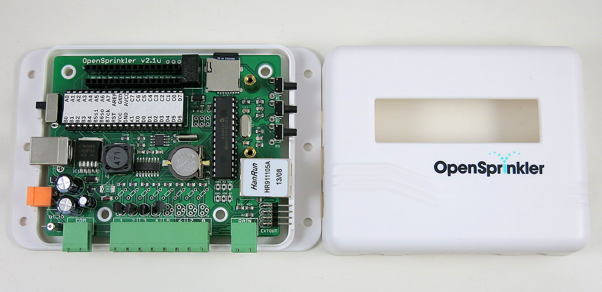
Continuing from yesterday’s post, today’s sneak peak preview is for OpenSprinkler DIY v2.1u — the solder-and-assemble-yourself version of the OpenSprinkler.
This is the first major upgrade of the DIY version since v1.42u. The main differences compared to 1.42u are:
- The microcontroller is upgraded to ATmega644, doubling the flash and RAM size of ATmega328.
- Switching regulator changed to LM2596S-5.0, which is beefier than MC34063.
- Added microSD card slot, space to fit MOVs, and pin headers to fit an RF transmitter.
- Enclosure is changed to use the injection molded case.
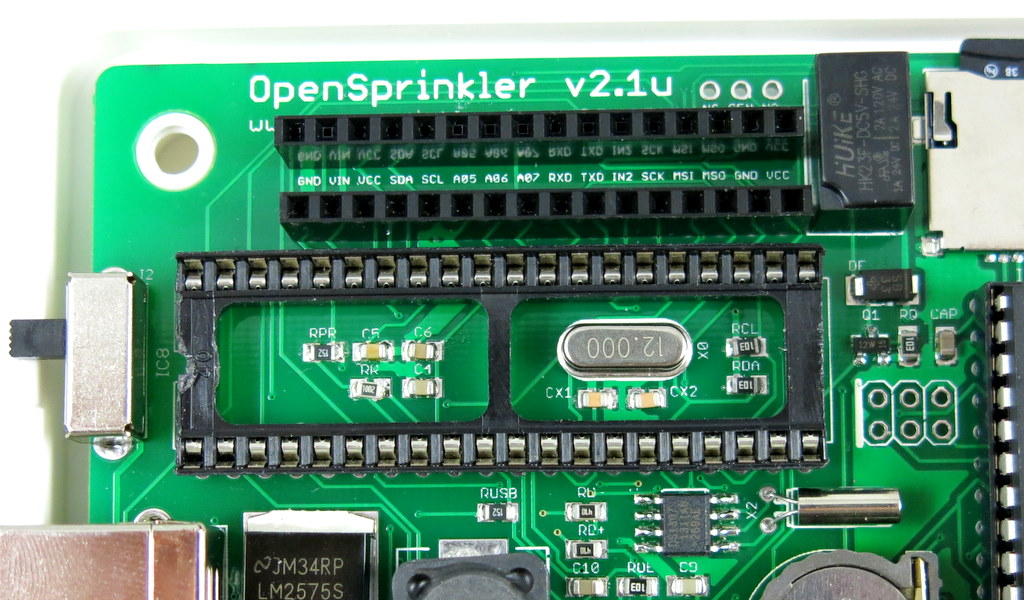
The design is pretty much similar to the fully assembled OpenSprinkler 2.0. To make it easy to solder, some components are been changed to use through-hole version, notably the ATmega644 microcontroller, the ENC28J60 Ethernet controller, triacs, and several capacitors. Due to the limited space (particularly as the through-hole ATmega644 is so much larger than the previous ATmega328), it’s not possible to keep all components in through-hole style. In fact, even with surface mount, I ended up using the trick of hiding some components underneath the microcontroller, as shown in the picture below:
In addition, the microSD card slot and the LM2596S regulator are not well-suited for hand-soldering. So unlike v1.42u, which uses all through-hole components, v2.1u will be in the form of hybrid SMT and through-hole — The SMT components will be pre-assembled, and the through-hole components will be soldered by users. Strictly this should be called semi-assembled OpenSprinkler.
While the hybrid solution may sound disappointing to DIY lovers, I figured this is still an interesting compromise, as it leaves sufficient flexibility for anyone who wants to tinker with it. For example, the mcu can be easily upgraded to ATmega1284, which is pin compatible with ATmega644 but has 128KB flash and 16KB RAM. Also, the triacs can be replaced by transistors or MOSFETs to interface with DC devices. So we will see if there is enough interest in this new experiment. If you are looking for an all through-hole version, I have to say 1.42u remains the best solution.

Now, why is this version numbered 2.1? Is it jumping ahead of the fully assembled OpenSprinkler 2.0? That’s right — there are some minor improvements / changes from 2.0, so I figured a new revision number is necessary to tell them apart. Here are the main differences:
First, the ATtiny45 (which functions as a USBtiny programmer) has been removed, partly to save space, and partly to simplify the design. Instead, the ATmega644 will be flashed with a USBasp bootloader, which allows itself to function as a USBasp programmer in bootload mode. This will take away 2KB of flash memory space, but on the plus side, it eliminates one chip, and the transfer speed of USBasp is actually noticeably faster than USBtiny. Additionally, using ATmega644 to directly handle USB tasks (thanks to the V-USB library) makes it possible to add USB serial functionality. As a result, you can do serial communication to debug the code, without any external USB serial converter. So it’s win-win-win 🙂 The details can be found in my previous blog post about USB HID-class Serial Communication for AVRs.
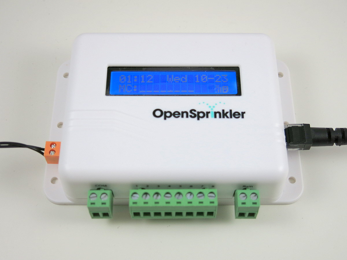
Next, the 24VAC port has been changed to use a new type of screw terminal that has smaller pin spacing and orange color. This will prevent users from accidentally plugging it into the COM or Rain Sensor port, which would damage the controller. A 2amp fuse on the 24VAC line, and a current limiting resistor for the Rain Sensor port has also been introduced for added protection. Finally, a relay has been added on digital pin D14, to allow general-purpose switching need, such as opening garage door, and power line device etc.
Due to these changes, particularly the USBasp bootloader (which requires ATmega644 to run at 12MHz instead of the current 8MHz on OpenSprinkler 2.0), it’s necessary to use a new revision number to avoid confusion.
In any case, the prototype has been verified and I only identified a couple of minor changes to fix. Otherwise it’s pretty much ready to go. It should be available for purchase within a month. So stay tuned!
