OpenSprinkler v2.2u Build Instructions
(Note: all images below are ‘clickable’, in order for you to see the full-resolution details. )
- Part 0: Parts Check
- Part 1: Soldering
- Part 2: Testing
- Part 3: Enclosure
To Begin: Parts Check
|
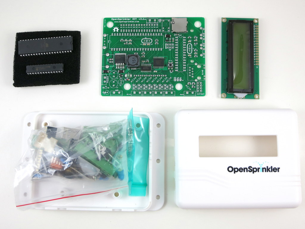
OpenSprinkler v2.2u kit includes a semi-assembled circuit board, through-hole components, LCD, and plastic enclosure..
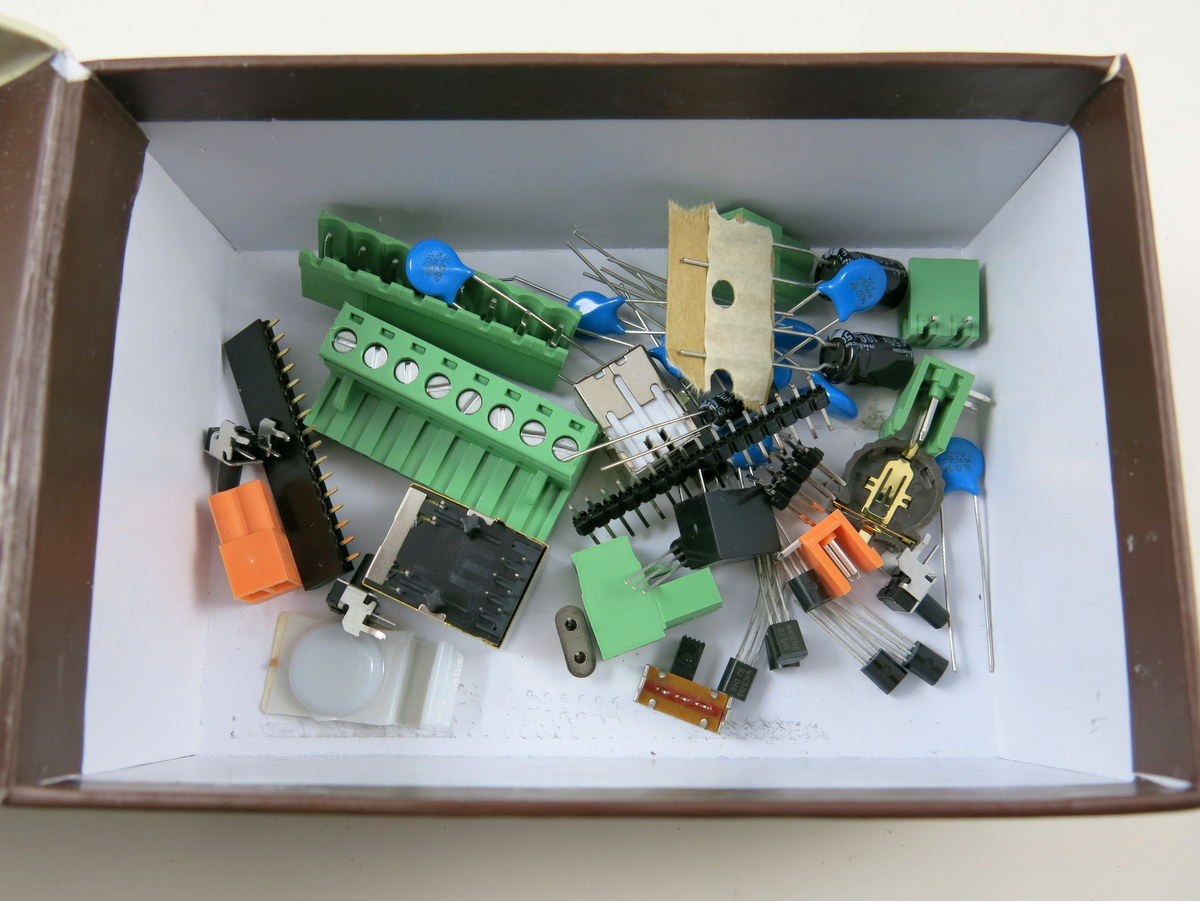
If you are new to soldering, please take a look at the Preparation page. The most important tool is a good and hot soldering iron: it should provide high temperature to melt and reflow solder. Cold soldering iron is a major source of soldering failure. Warning: electronic components are small and easy to lose. Before soldering, carefully place the components in a box or container. Small components may get stuck in the plastic bag. DO NOT throw away the plastic bag until you are done with soldering. |
 |
Additionally, you need a sprinkler valve transformer (rated 24∼28V AC) and one or more sprinkler valves. These are not included in the kit. You need to purchase them separately. If you have an existing sprinkler system, you should have these parts already installed, and you can reuse your existing sprinkler transformer; if not, you can purchase them online or at local retail stores. They are available in many brands and a variety of places (Lowes, Home Depot, Amazon…). |
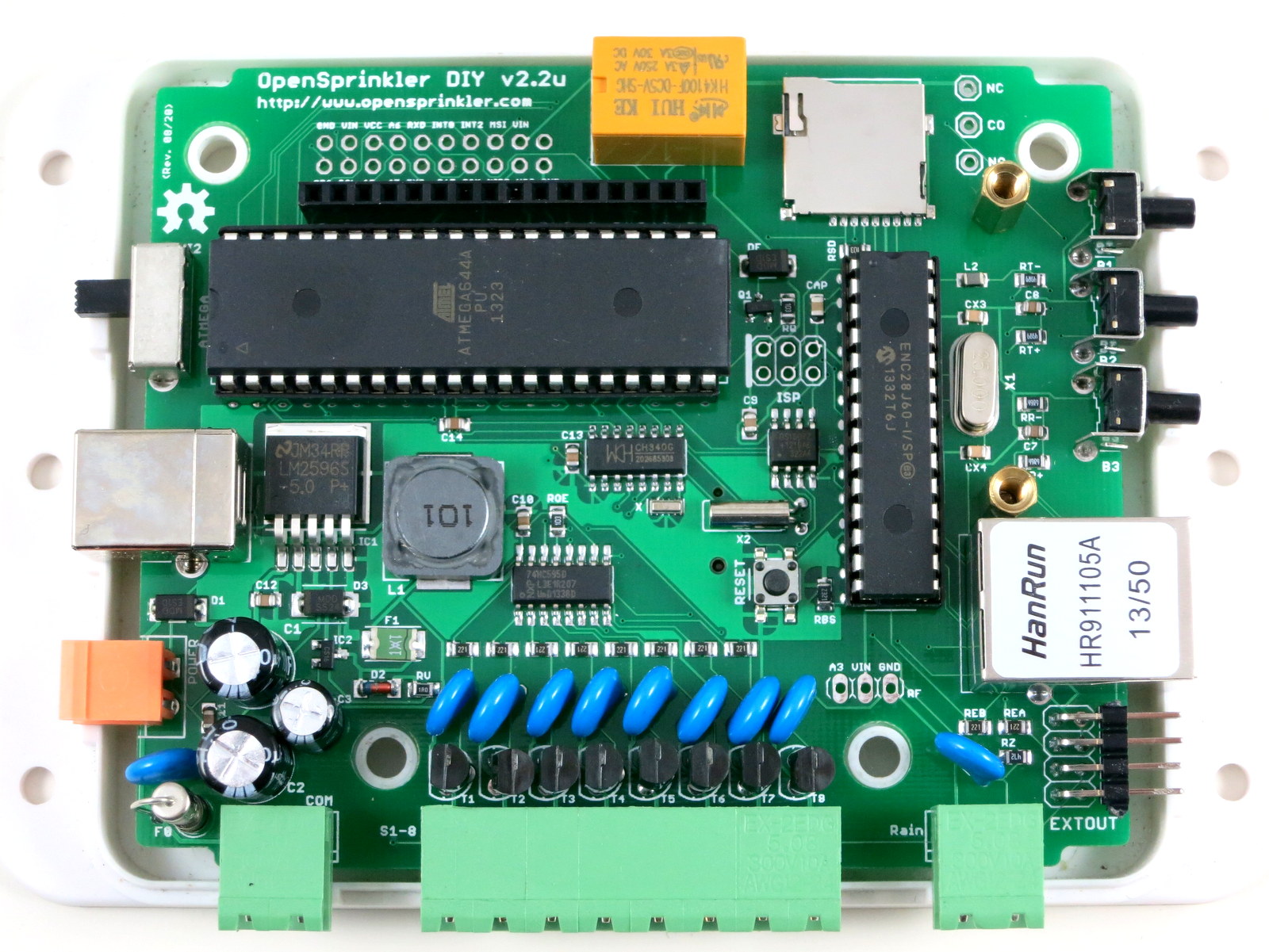
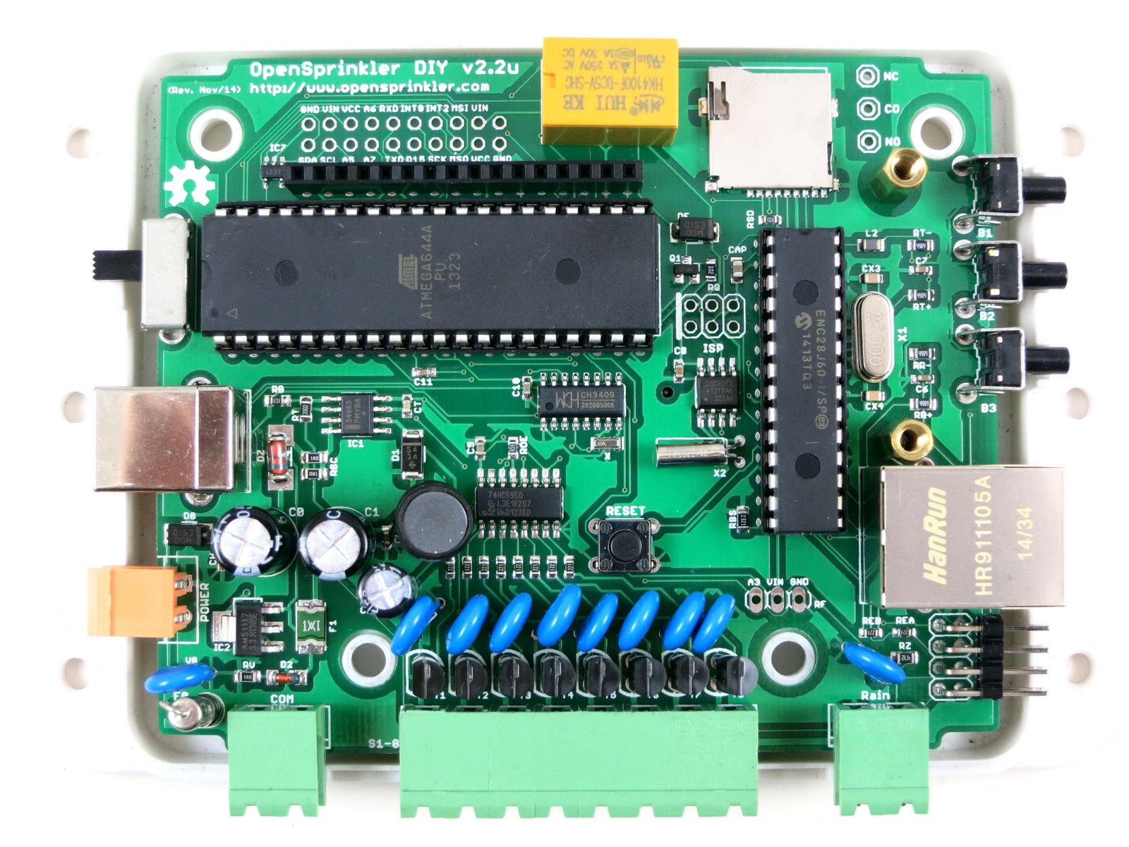
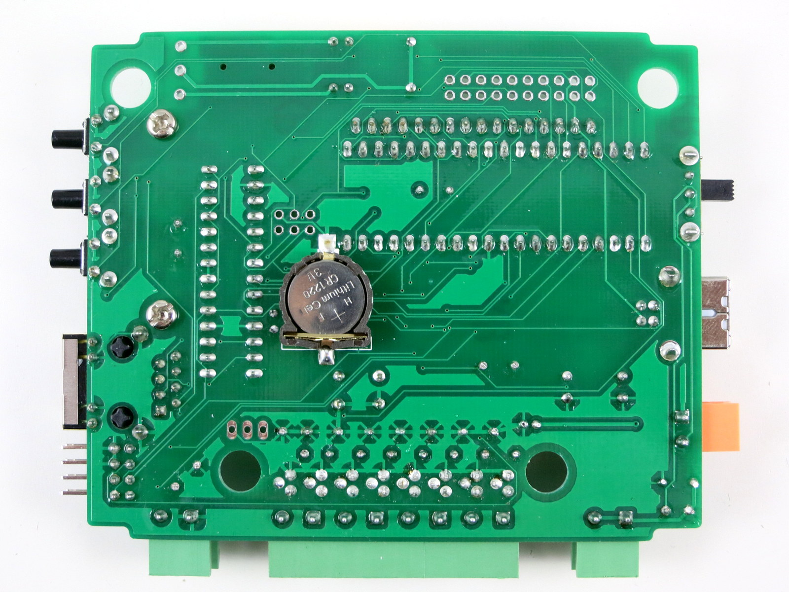
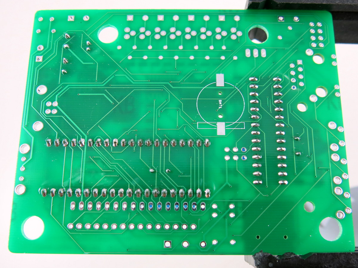
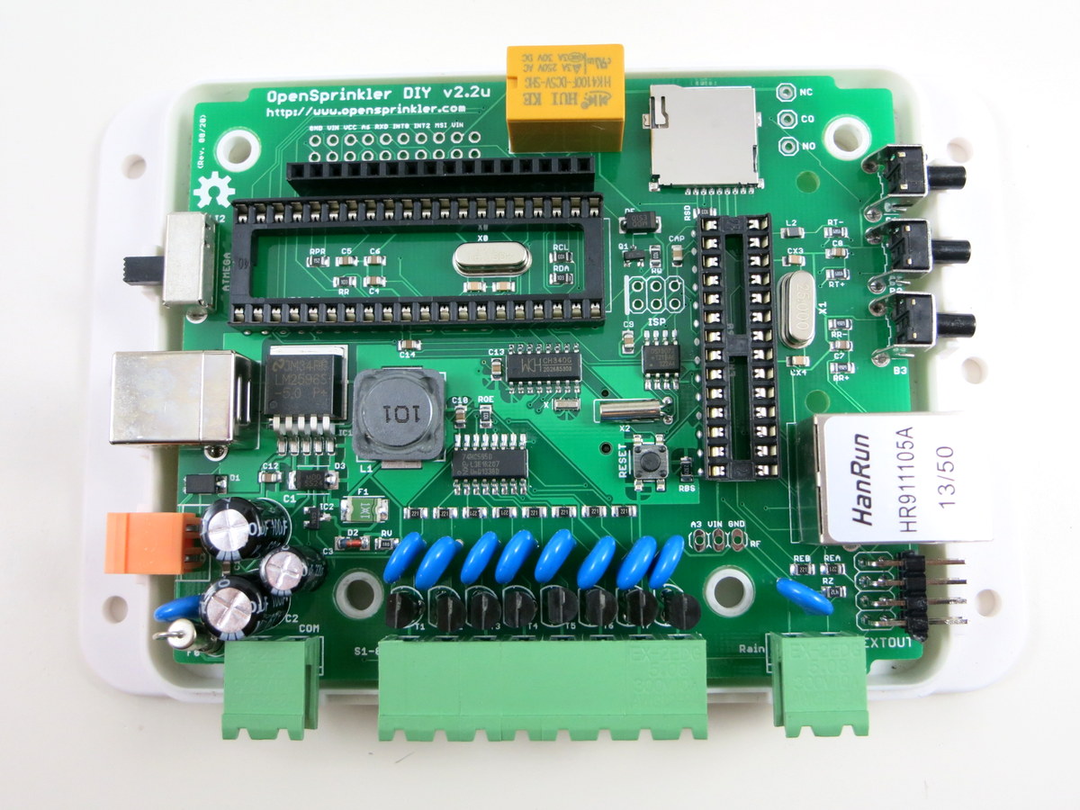
| To give you a heads up, here are two high resolution images of the assembled board (front and back). Click the images to see them in full resolution.
|
|
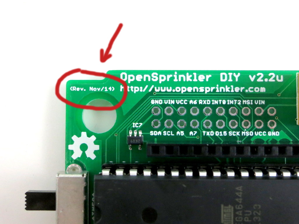 |
Update: if you have received the Nov 14 Revision of DIY 2.2u (check the upper-left corner of the PCB and see if it says Rev. Nov/14), the reference images of the assembled board as below:
|

Part 1: Soldering
 |
To begin, place the PCB onto a a vise, and turn on the soldering iron. (If possible, use a fume extractor to help remove solder fumes).
Remember: all images on this page are ‘clickable’. |
|
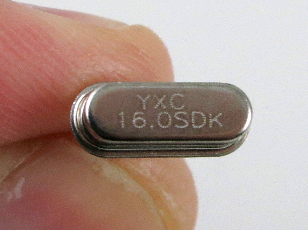
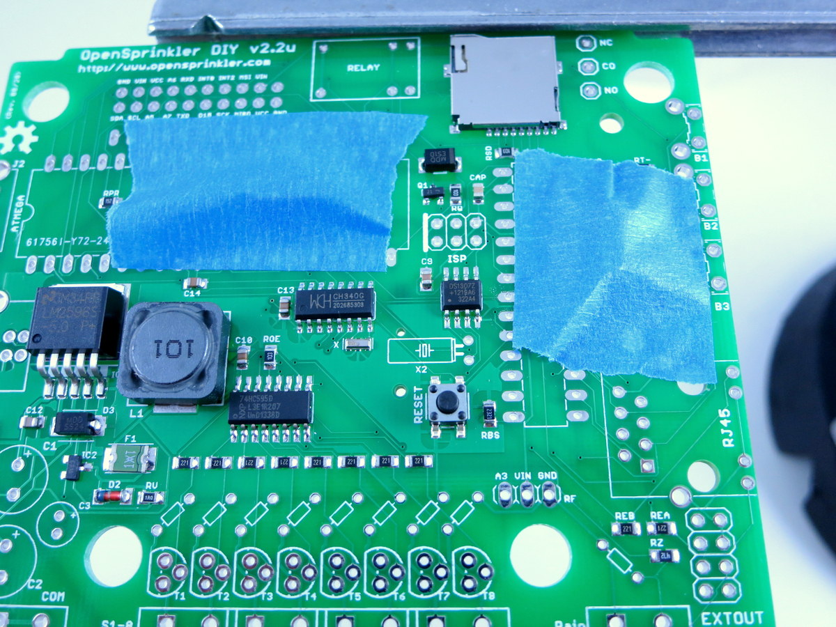
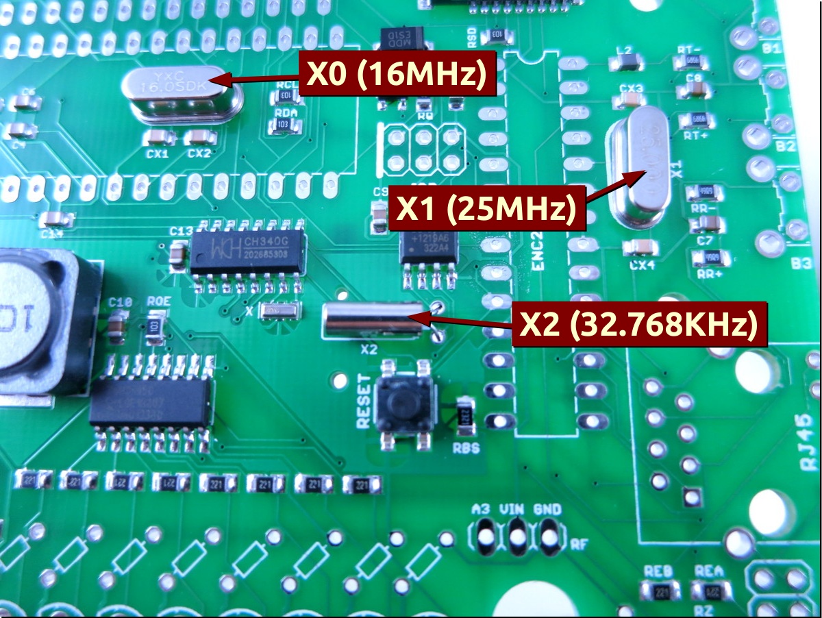
Start with crystals X0 (16MHz) and X1 (25MHz). The two crystals have exactly the same shape, so you must read the label on the components to tell them apart. Check the images on the left to see where they are located. It’s important you don’t mix them up, otherwise the controller will not work. Crystals are non-polar, so it doesn’t matter which orientation you insert them.
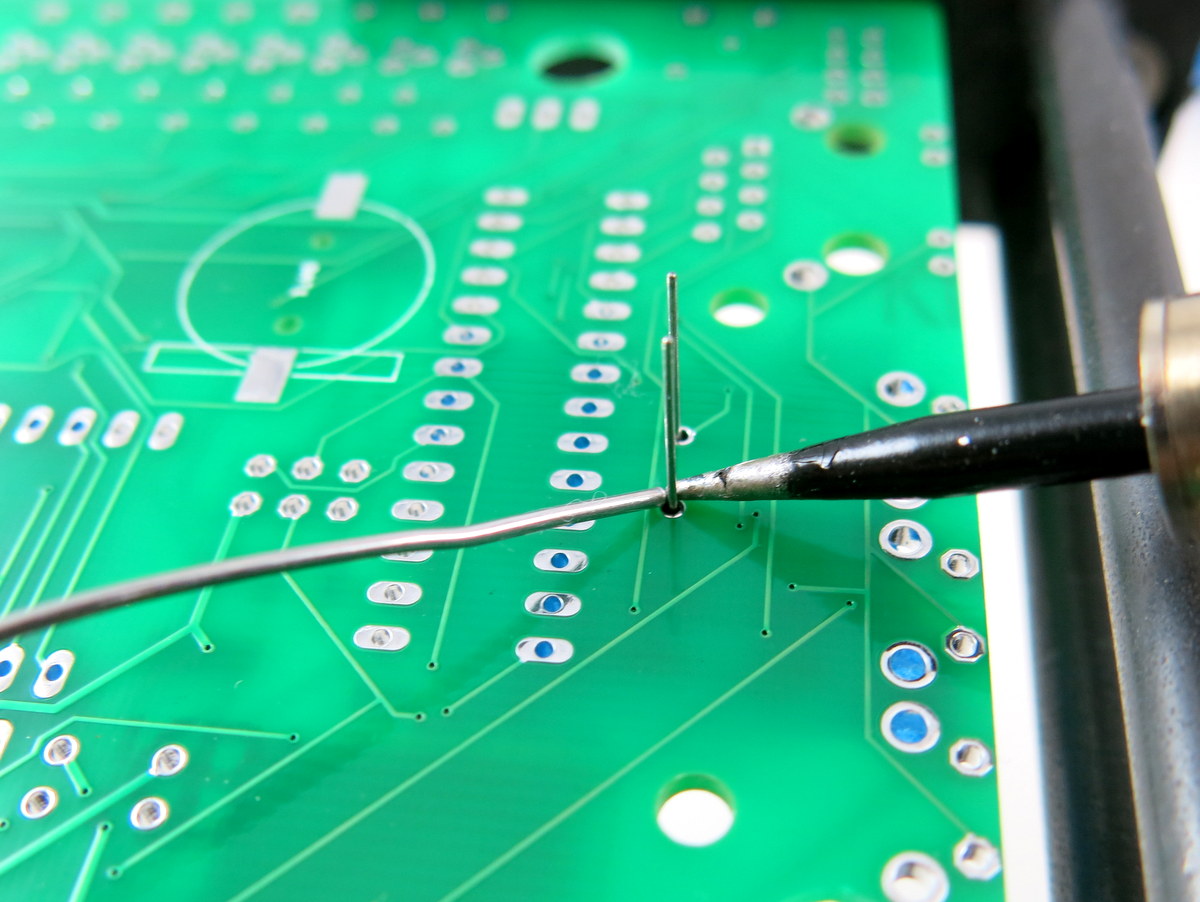
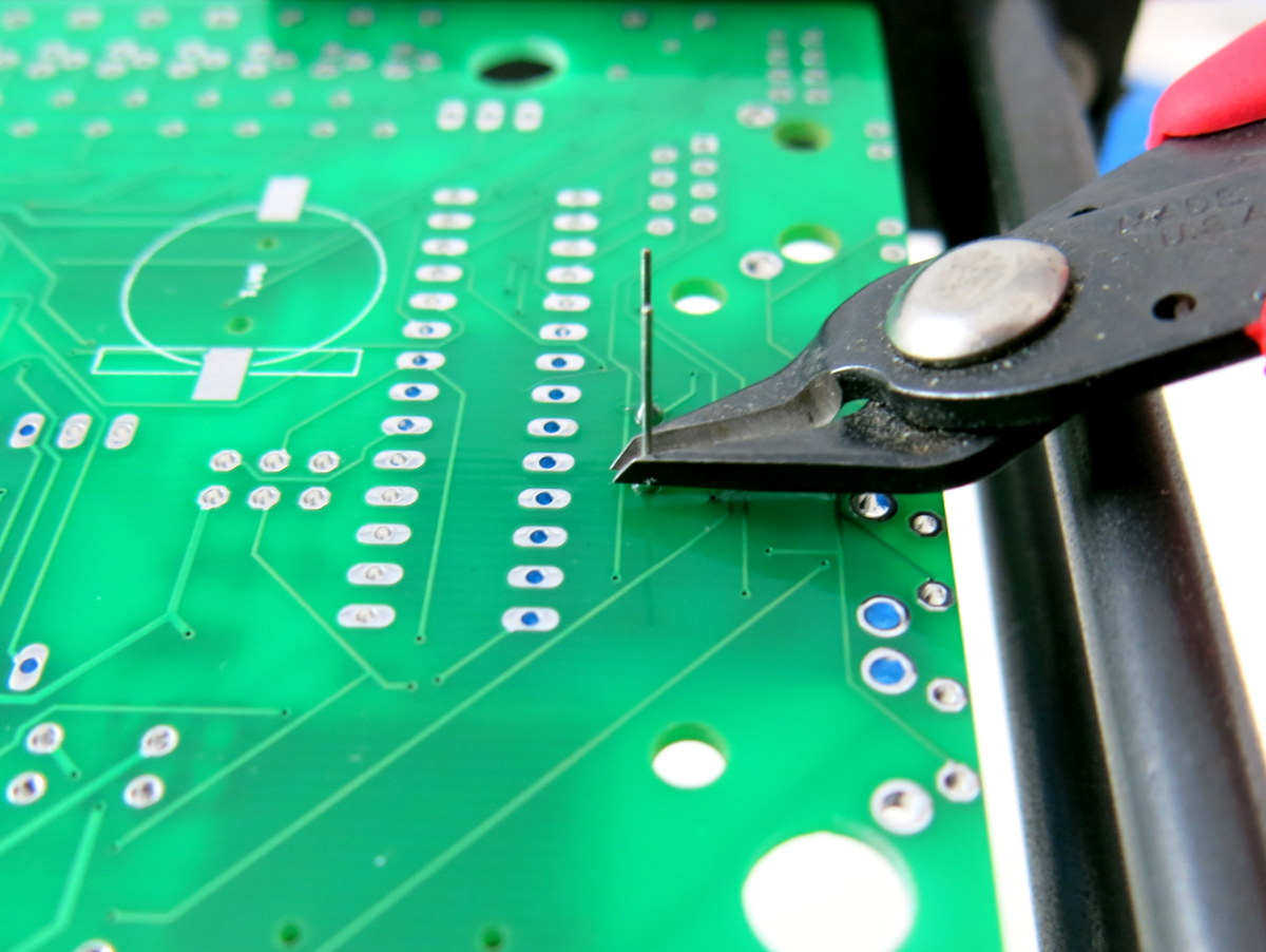
To solder, insert the components through the PCB holes. To increase productivity, I usually insert multiple components, and use painter’s tape to fix them in place (see image on the left). You can use as many pieces of tapes as you need. Then flip the PCB and solder all leads. This way you can solder multiple components at once. Make sure your soldering iron is hot, and can easily melt and reflow solder. After soldering, use a diagonal cutter to clip the excessive leads. Next, also solder crystal X2 — it’s a 32.768kHz cylindrical crystal for the Real-Time Clock (RTC). See picture on the left.
|
|
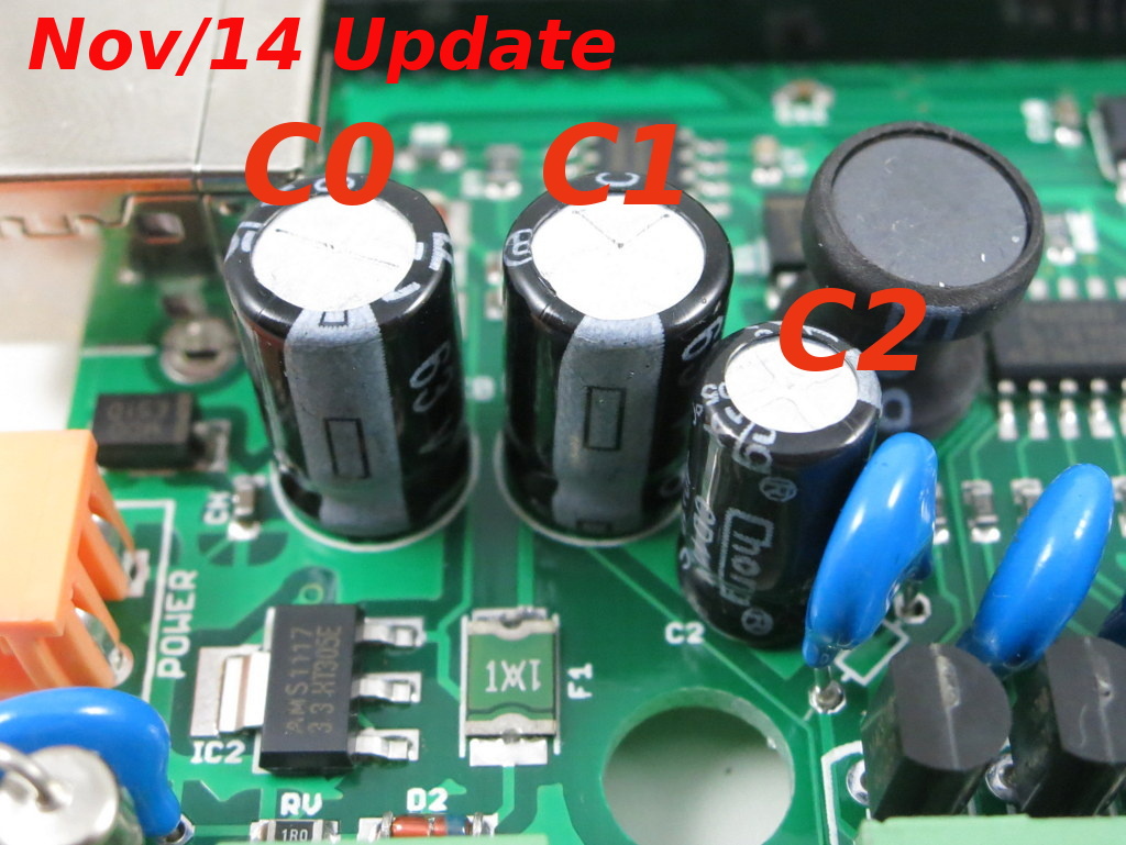
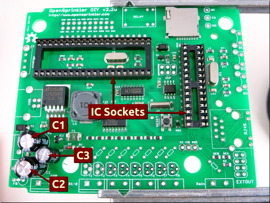
(Update:: on the Nov/14 Revision, the capacitors C1, C2, C3 below are renamed C0, C1, C2, and their positions are shown in the picture on the left).
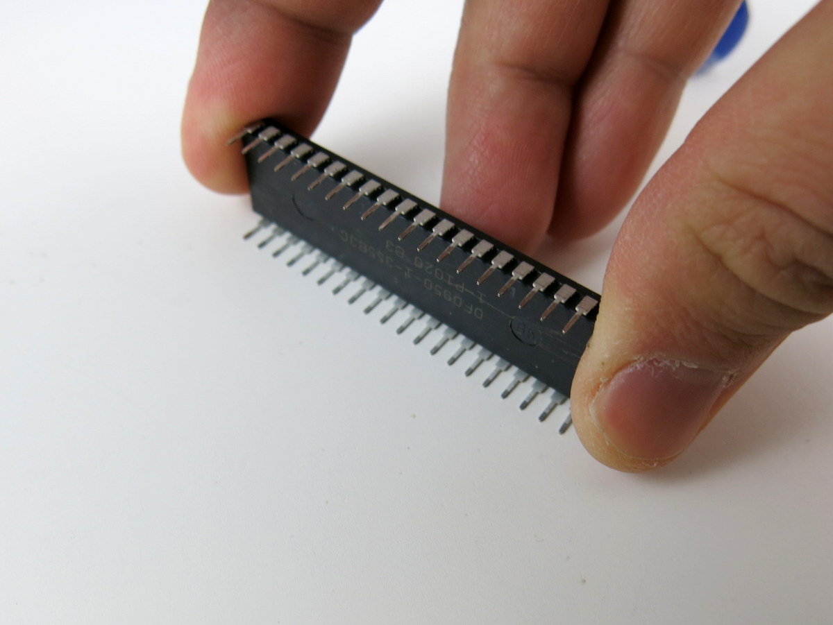
Now solder C1, a big electrolytic capacitor. Electrolytic capacitors are polarized: make sure the longer (positive) lead goes into the hole marked with +. To double check, there is a white stripe on the capacitor body which points to the negative lead. Continue to solder C2 (same size as C1), and C3 (smaller). Again, make sure the longer lead goes to the hole marked +. Next, solder the two IC sockets (40-pin and 28-pin). Before inserting the IC sockets to the PCB, check to make sure all pins are straight. Every socket has a small notch (see the picture below) to help identify the orientation. This notch should match up with the silkscreen on the PCB. After insertion, double check and make sure no pin is left out or twisted. The solder joints should be clean and free of any solder bridge.
|

|
Now solder the fuse — bend one pin down and seat it vertically on the PCB. Then solder the two leads and clip. The fuse is non-polar. |
|
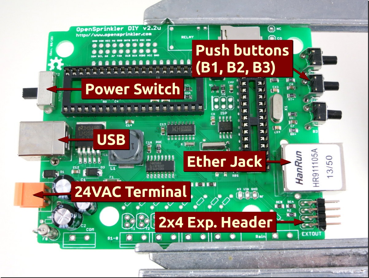
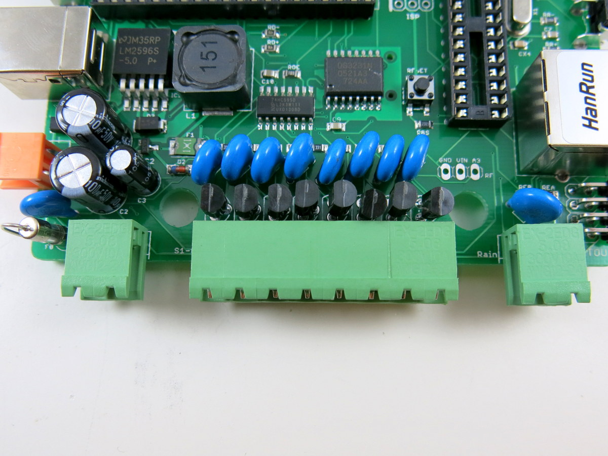
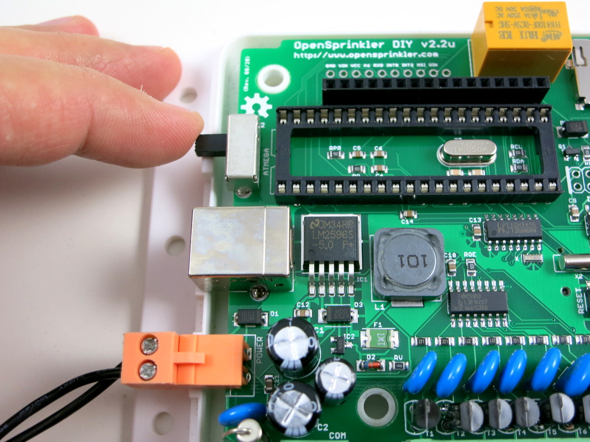
Moving on, now you will solder a bunch of peripheral components: power switch, USB connector, 24VAC terminal block (orange color, 4mm spacing), three push-buttons, Ethernet Jack, and the 2×4 expansion board pin headers.
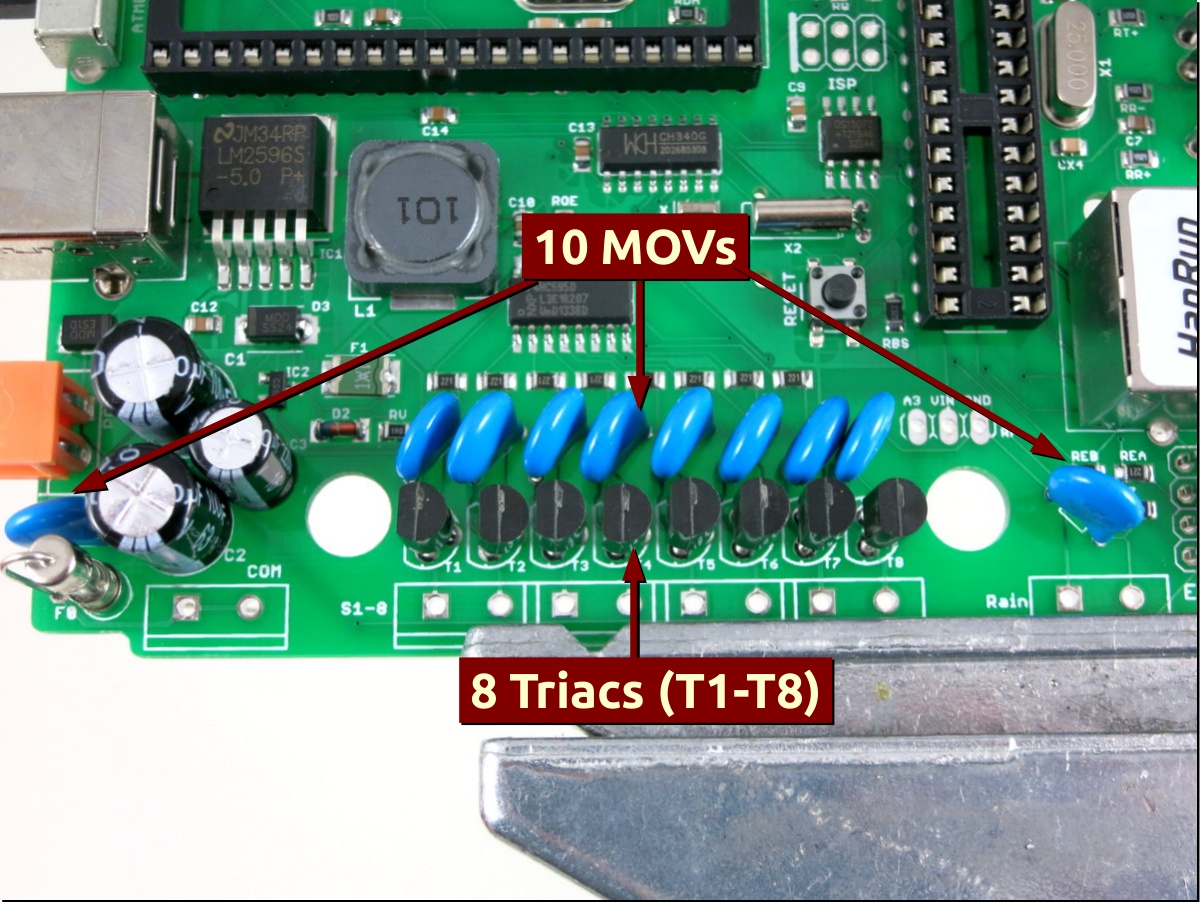
Also solder the 10 metal oxide varistors (MOVs). Each MOV is a blue, disc-shaped component. It’s non-polar, and its main purpose is to absorb transient high voltage and protect the circuit from power surge or lightening. Next, solder the eight triacs T1-T8 (MAC97). Each triac is shaped like a half cylinder. Orient it such that the half cylinder matches the PCB silkscreen (i.e. the flat side should face the fuse and orange terminal block). Use your hand to bend the middle pin slightly towards the back, so that you can easily insert it to the PCB holes. |

|
Update:: on the Nov/14 Revision, solder inductor L1, a black, cylindrical, non-polar component; and then solder the RESET tactile button. |
|
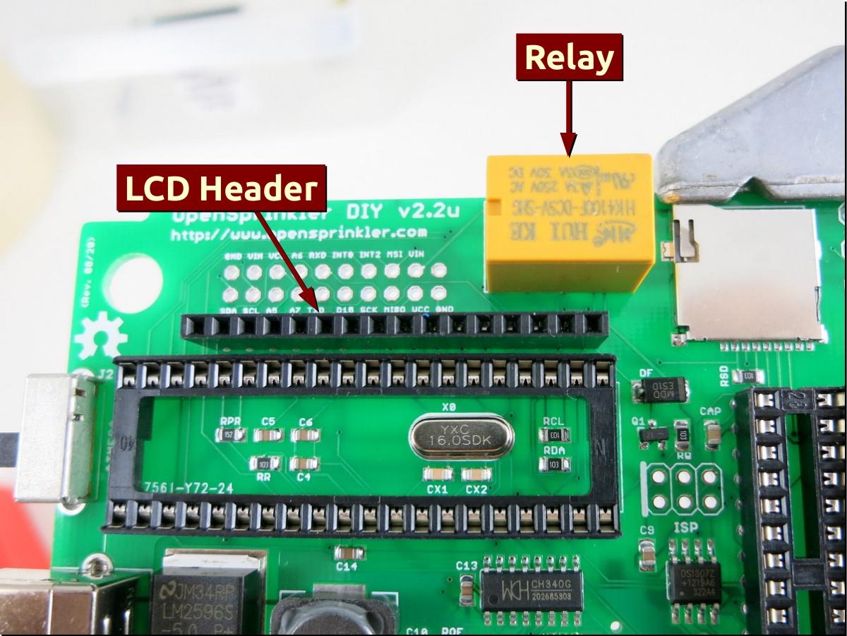
Solder the yellow-colored relay and the 1×16 LCD female pin header.
It’s important that the pin header is seated straight and tight on the PCB. Try to avoid any gap between the pin header and the PCB, otherwise it will be difficult to put the cover on later. |
 |
Now take out the LCD and the 1×16 male header. Solder the male header onto the LCD. The easiest way to do so is by making use of a breadboard to hold the pin header during soldering. Again, it’s important that the pin header is seated tightly to the LCD’s PCB. |
|
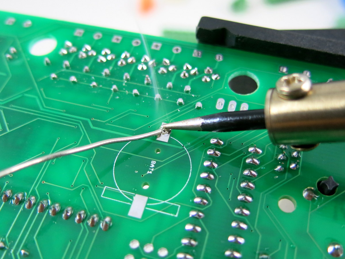
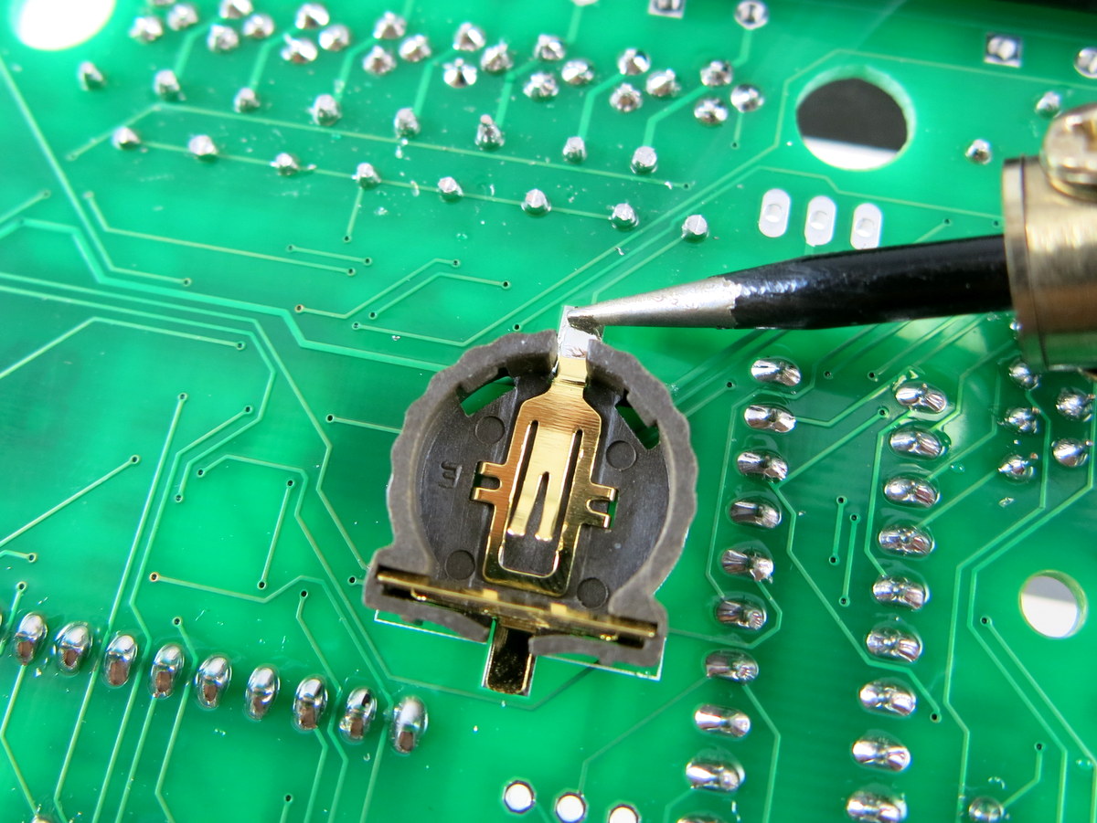
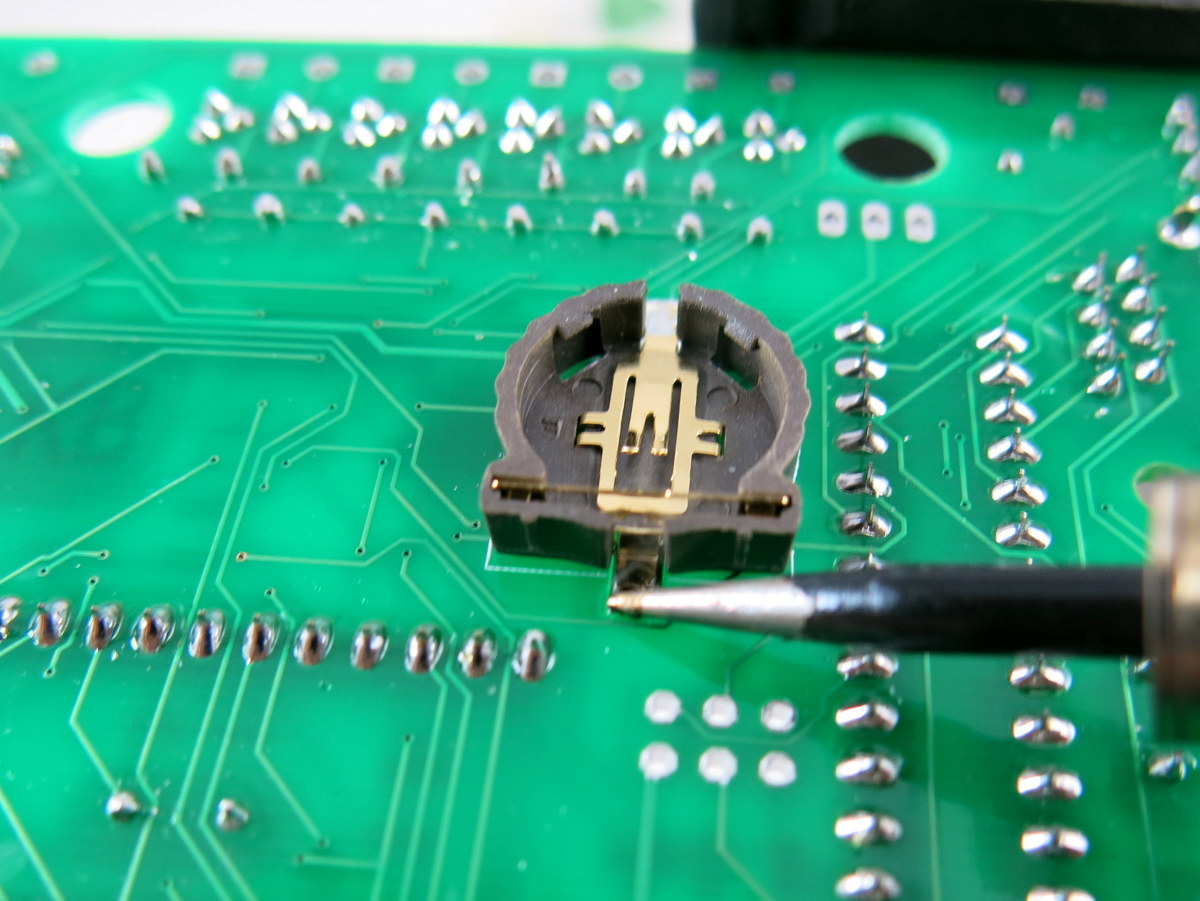
Now flip the PCB and solder the 12mm battery holder. To begin, use a small amount of solder to tin the PCB pad. Then place the battery holder down and make sure the orientation matches the silkscreen (rectangular and circular parts). Solder one pad first, and then the other pad. Make sure both solder joints are reliable.
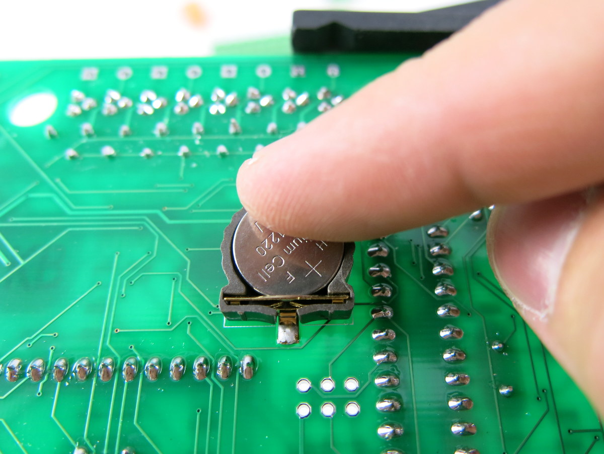
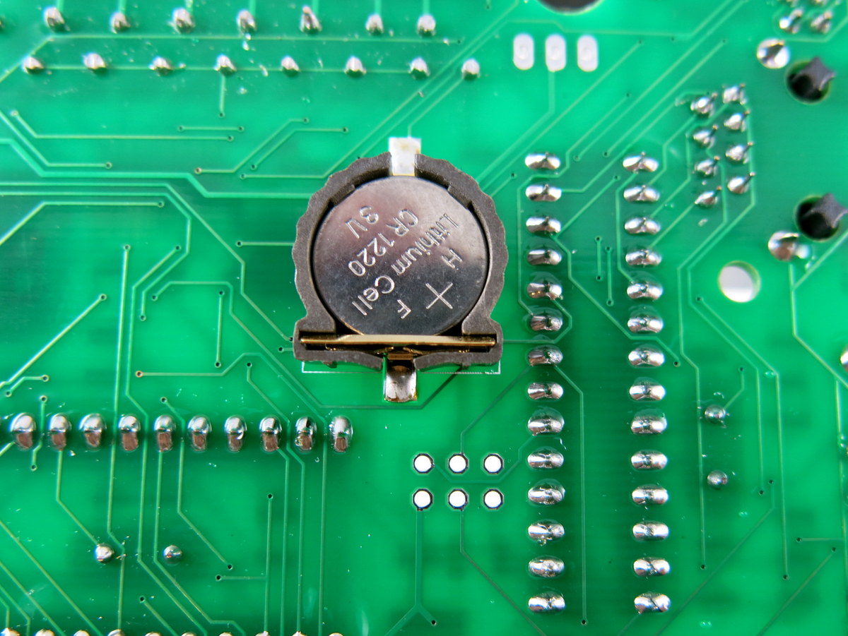
After the battery holder is soldered on, take out the CR1220 battery, and snap it into the holder. The flat side (marked by +) should face up. The easiest way is to first insert the battery towards the side with a straight metal piece, then press the battery firmly to snap it in. If you ever need to take the battery out, push the straight metal piece as much as you can, until the battery pops out.
|
|
Finally, solder the remaining two 2p terminal blocks and one 8p terminal block. These terminal blocks have green color and 5.08 pin spacing.
Voilà, you are all set with soldering! Carefully check your board with the image below. At this point, DO NOT pop in the two ICs yet because we will do voltage testing first (see below).
|

Part 2: Testing
|
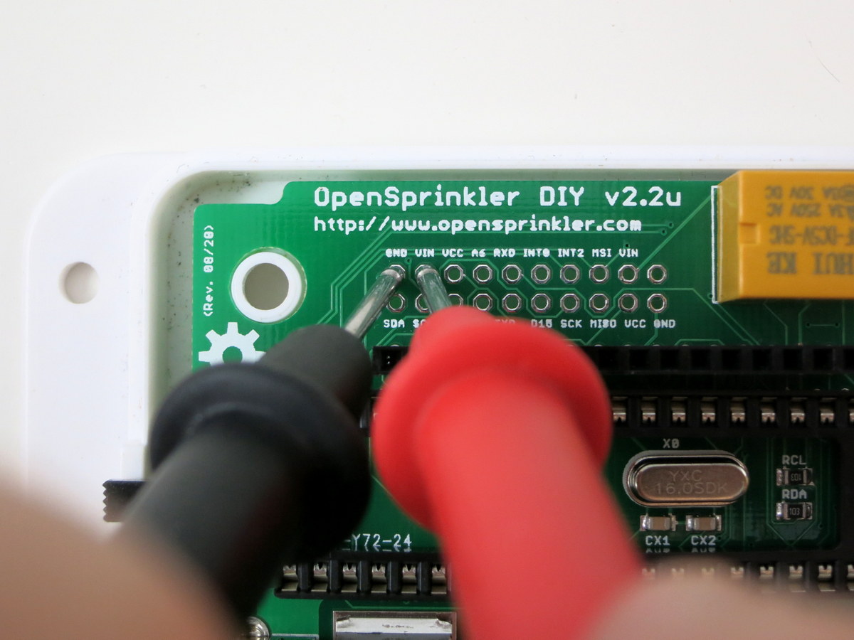
In this section, you will test the circuit and make sure it functions. If you’ve already inserted the two ICs, take them out for now.
First, measure the resistance between VIN (+5V) and GND as well as between VCC and GND. These pins can be located in the pinout area above the LCD headers. The resistance should be at least a few hundred ohms. If either resistance is below 500 ohms, there is probably a shorting or solder bridge somewhere. Next, take out the orange terminal block, wire in 24VAC power, and insert it to the 24VAC port on the left side of the circuit board. Slide down the power switch to turn it on. Measure the voltage between VIN and GND — it should be around 5V; also measure the voltage between VCC and GND — it should be around 3.3V. Important: if anything burns or smokes, immediately turn off power. Check to see if there is any component visibly damaged. If you can’t figure out the problem, post a message in the forum and we will help you. |
|
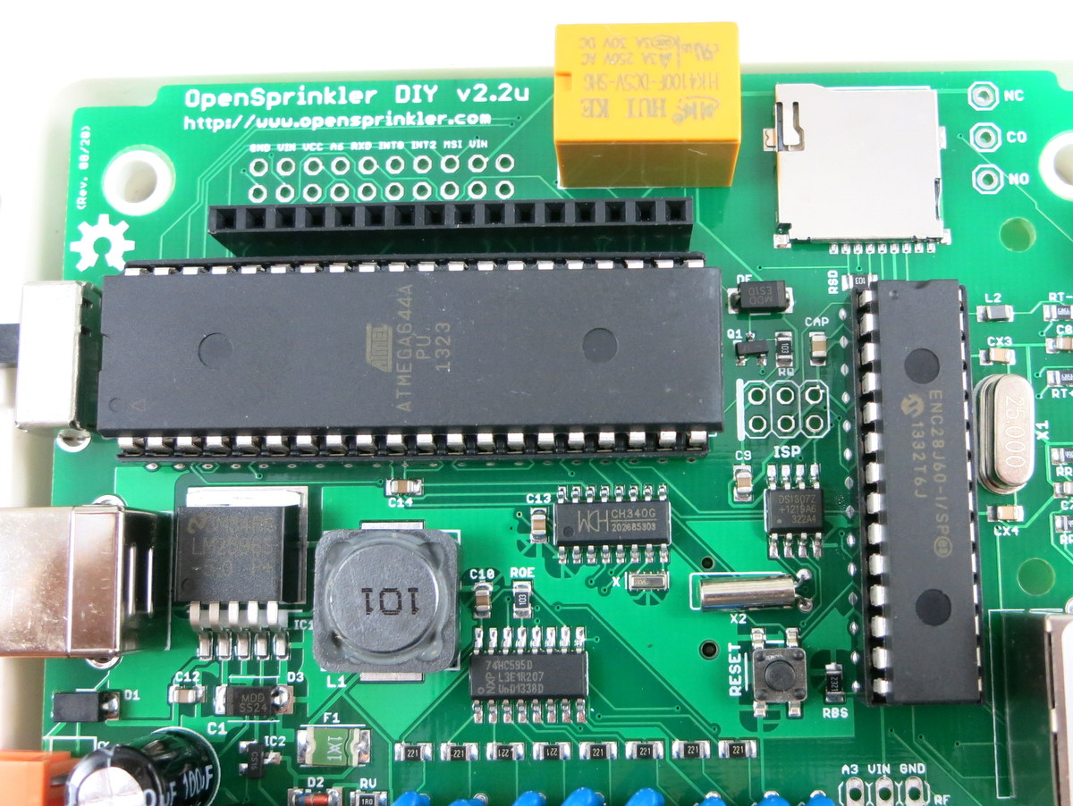
Once the voltage checking is passed, you can unplug the power, and go ahead to pop in the two ICs — ATmega644 microcontroller, and ENC28J60 Ethernet controller. To insert an IC, bend its pins slightly inward on a hard flat surface. While inserting, make sure no pins are left out or twisted.
Make sure that its notch matches the notch on the IC socket. If you’ve done it right, the notch on ATmega644 should face left, and the notch on ENC28J60 should face up. Check yours with the image on the left. |
|
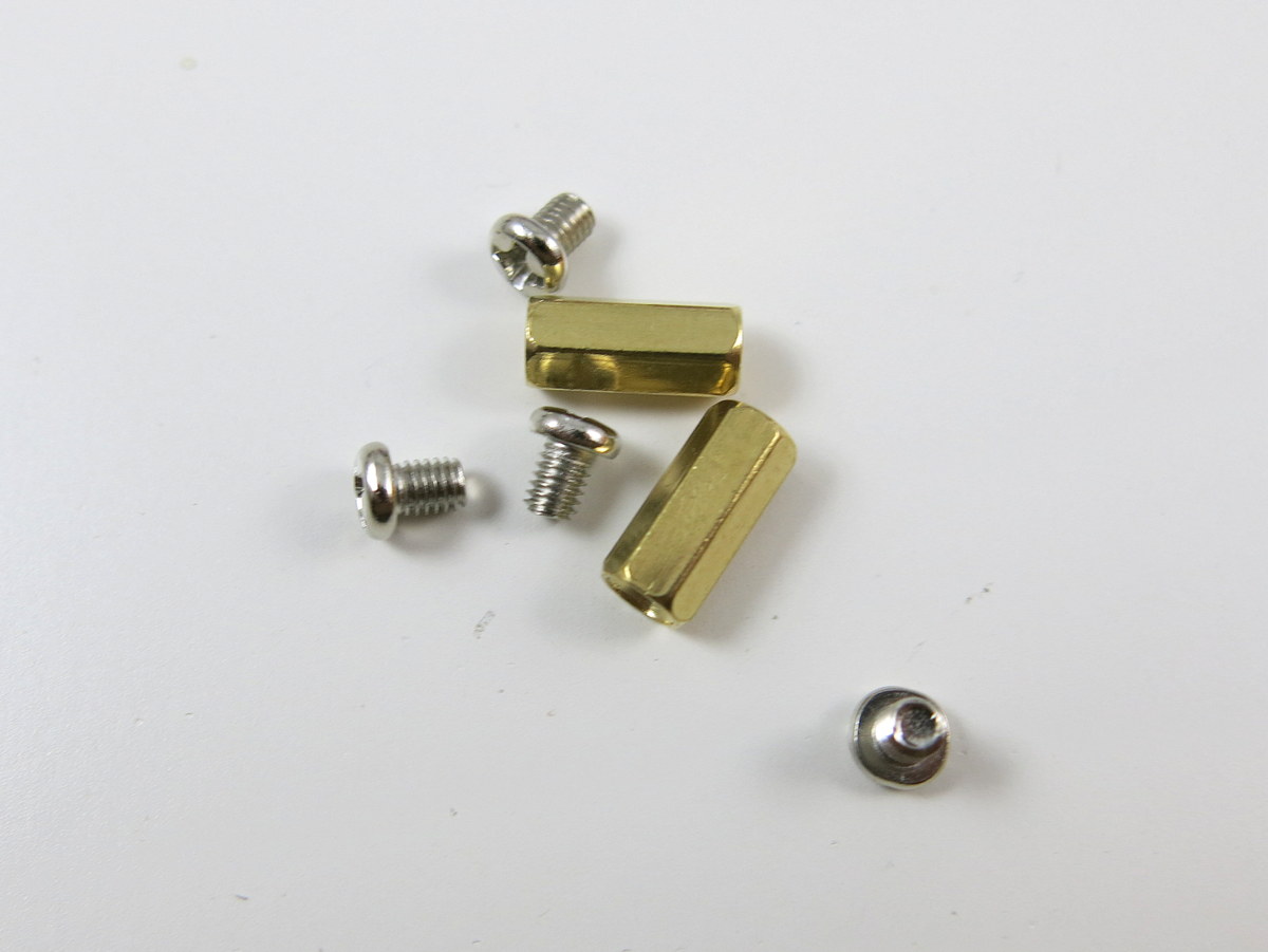
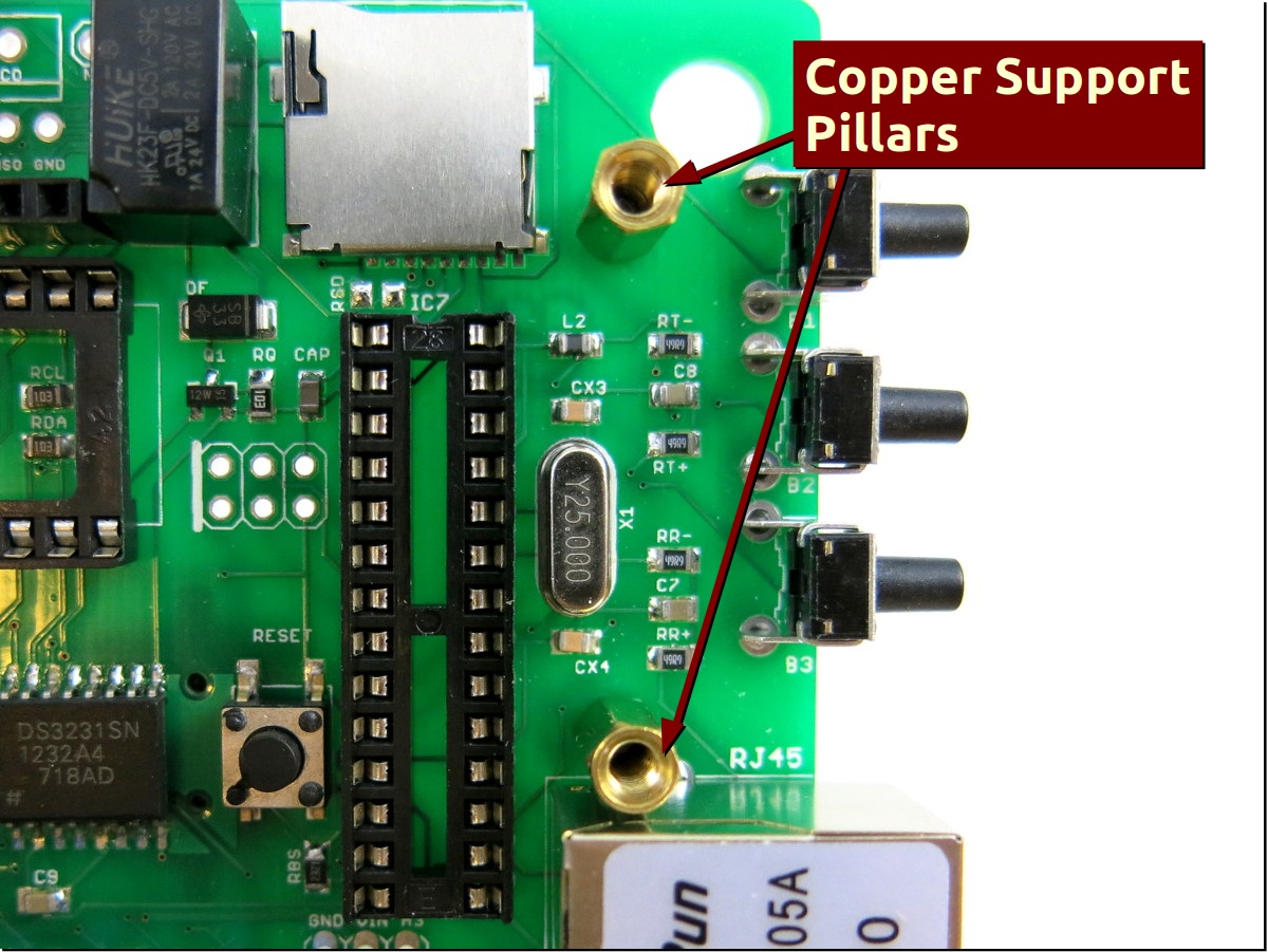
Now install the LCD. Start by using the M3 (3mm) screws to fix the two copper support pillars to the PCB.
NOTE: use moderate strength and DO NOT tighten the screws too much as that may damage the PCB traces. Then insert the LCD to the female pin headers, and finally use the other two M3 screws to tighten the LCD to the support pillars. |

|
Now you can power on the controller and check its firmware features. You can either plug in 24VAC, or use a USB cable to power the controller (DO NOT have both sources on at the same time). Using USB power won’t activate any sprinkler valve, but allows you to check firmware features and set IP address etc. before deploying the controller. The USB is mainly used for flashing new firmware, and it can be used to power an external WiFi adapter too. |
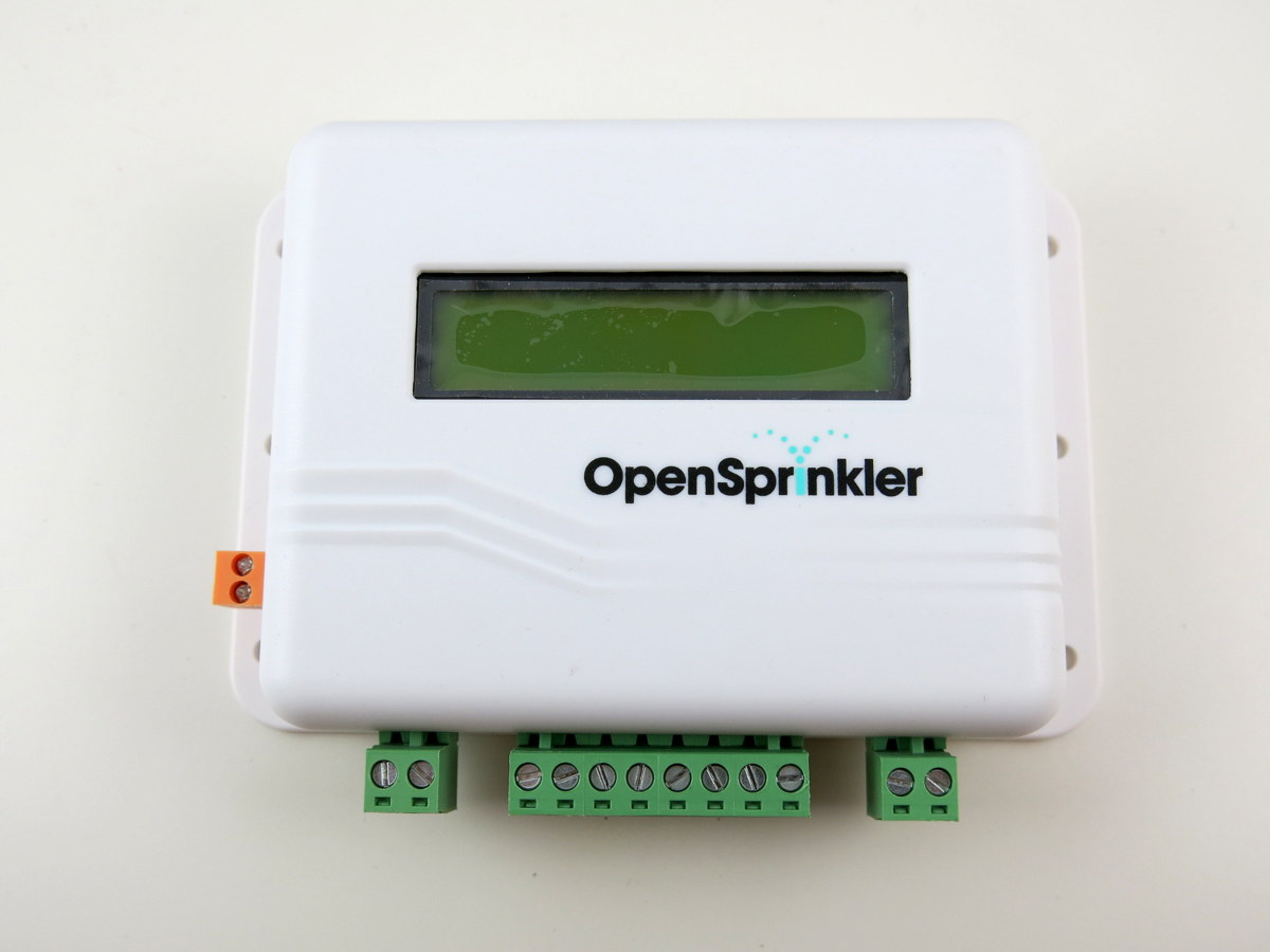
Part 3: Enclosure
|
OpenSprinkler v2.2u comes with a plastic enclosure. To install the enclosure, place the circuit board on the enclosure’s bottom piece, then cover it with the top piece. Flip the assembly upside down, and install the four screws. The screws are relatively big, and require a considerable amount of force to screw them in. It’s recommended that you use a electric screw driver to make it easy for you.
(Optional): the OpenSprinkler firmware supports using a microSD card to store logging data. To use this feature, prepare a microSD card (any size, formatted to FAT or FAT32), and insert it to the card slot (next to the yellow relay). The firmware will automatically detect the card and use it to store logging data. That’s all. Now you have a functioning OpenSprinkler. Congratulations, and hope you enjoy using it! |
