OpenSprinkler v1.42u Build Instructions
(Note: all images below are ‘clickable’, in order for you to see the full-resolution details. )
- Part 0: Parts Check
- Part 1: Soldering
- Part 2: Testing
- Part 3: Project Case
To Begin: Parts Check
|
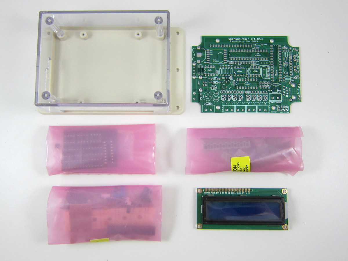
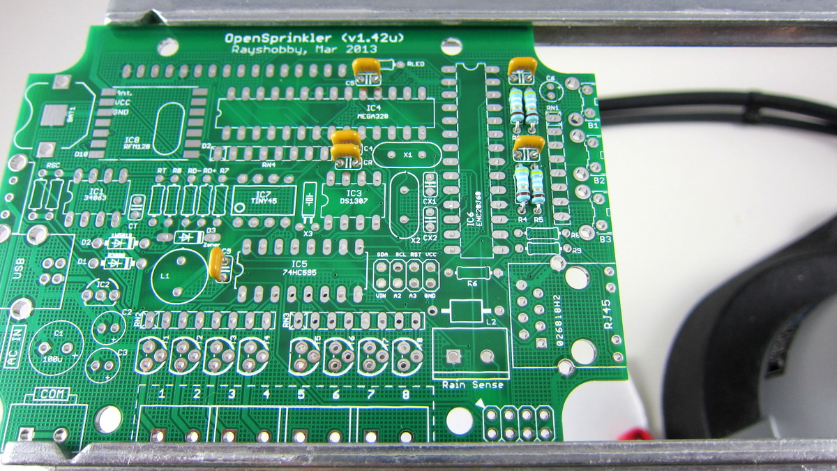
The kit includes all components you need to build OpenSprinkler v1.42u. The part list can be found on this page. As the picture shows, the kit includes the PCB, bags of components, LCD, and project enclosure.
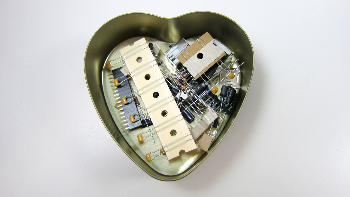
If you are new to soldering, please take a look at the Preparation page.The most important tool is a good and hot soldering iron: it should provide high temperature to melt and reflow solder. Cold soldering iron is a major source of soldering failure. Warning: electronic components are small and easy to lose. Before soldering, carefully pour the components in a container or mint tin. Sometimes a couple of components may get stuck on the sticker. DO NOT throw away the plastic bags until you are done with soldering. |
 |
Additionally, you need a sprinkler valve transformer (rated at 24∼26V AC) and one or more sprinkler valves. These are not included in the kit. You need to purchase them separately. If you have set up a watering or irrigation system in your garden, you should already have these parts installed; if not, you can purchase them online or at local retail stores. They are available in many brands (Orbit, Hunter, Rainbird…) and a variety of places (Lowes, Home Depot, Amazon…). Check the F.A.Q. page for some additional information. |
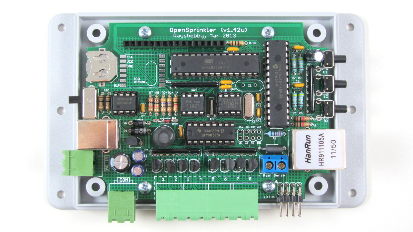
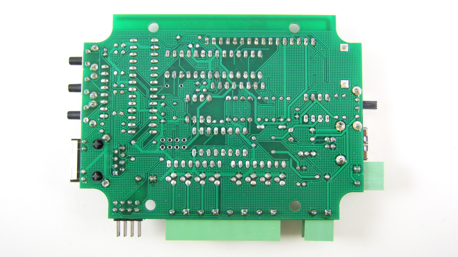
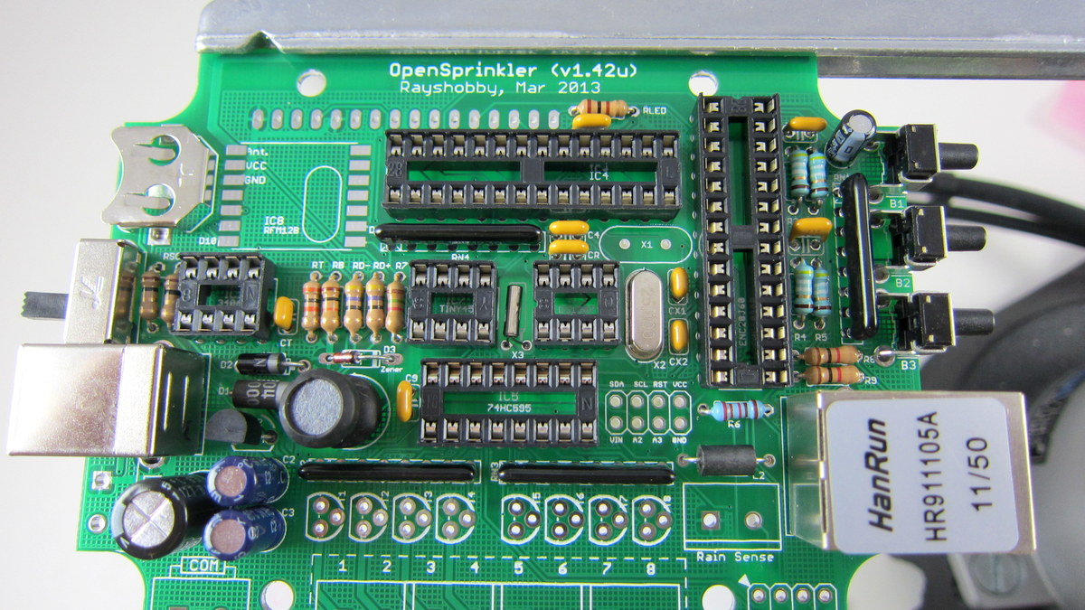
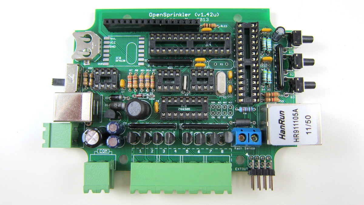
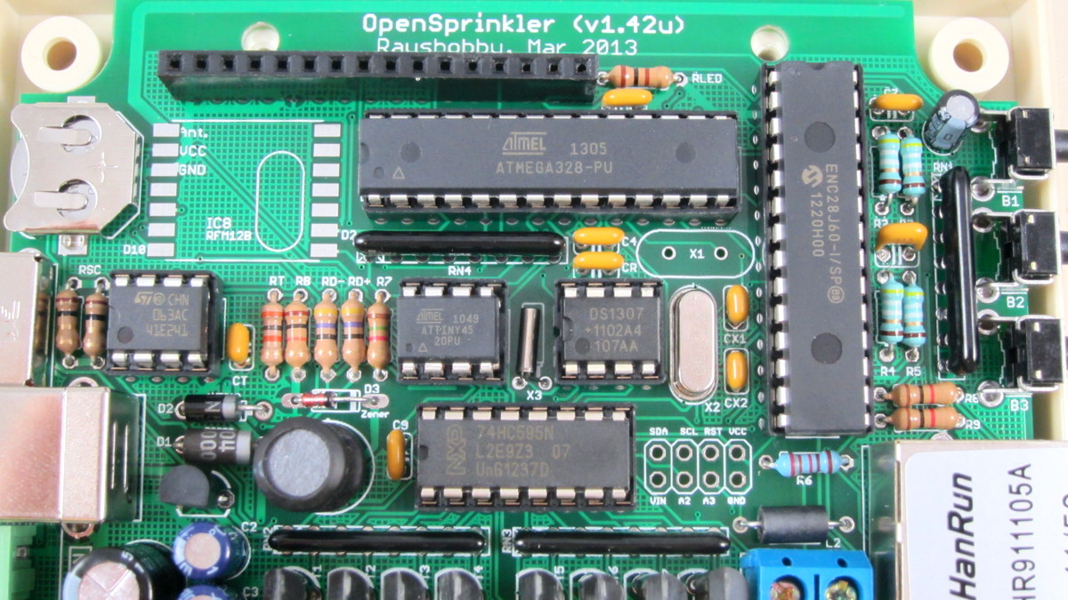
| To give you a heads up, here are two high resolution images of the assembled board (front and back). Click the images to see them in full resolution.
|
Part 1: Soldering
 |
To begin, place the PCB onto a a vise, and turn on the soldering iron. (Optional: use a fume extractor to help remove solder fumes).
Remember: all images are ‘clickable’. |
|
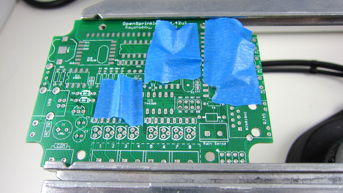
Start with the four 49.9 ohm resistors and size 0.1uF ceramic capacitors. Each set is on a strip so it’s easily to identify. These correspond to R2, R3, R4, R5 and C4, C5, CR, C7, C8, C9. Click the image on the left to see where they are located on the PCB. Especially pay attention to C9 — make sure you are not inserting it to CT. These components are non-polar, so it doesn’t matter which direction you insert them.
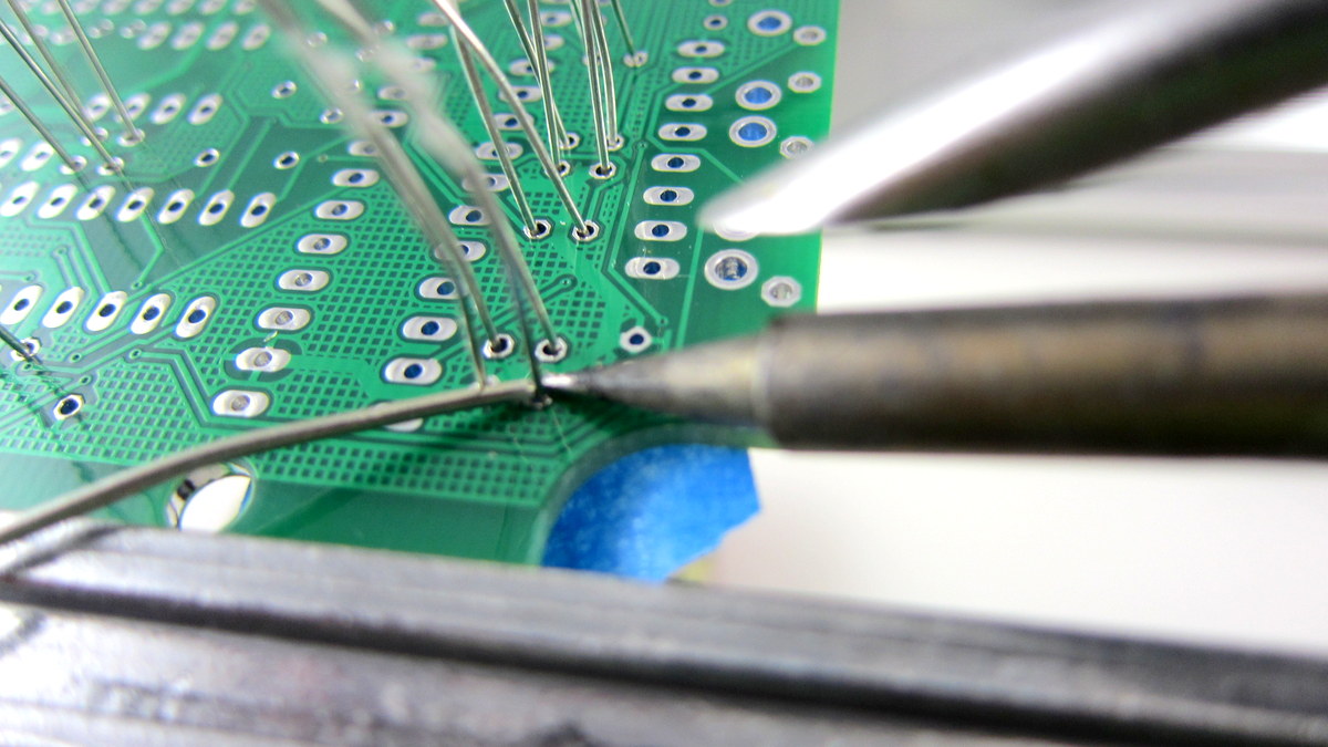
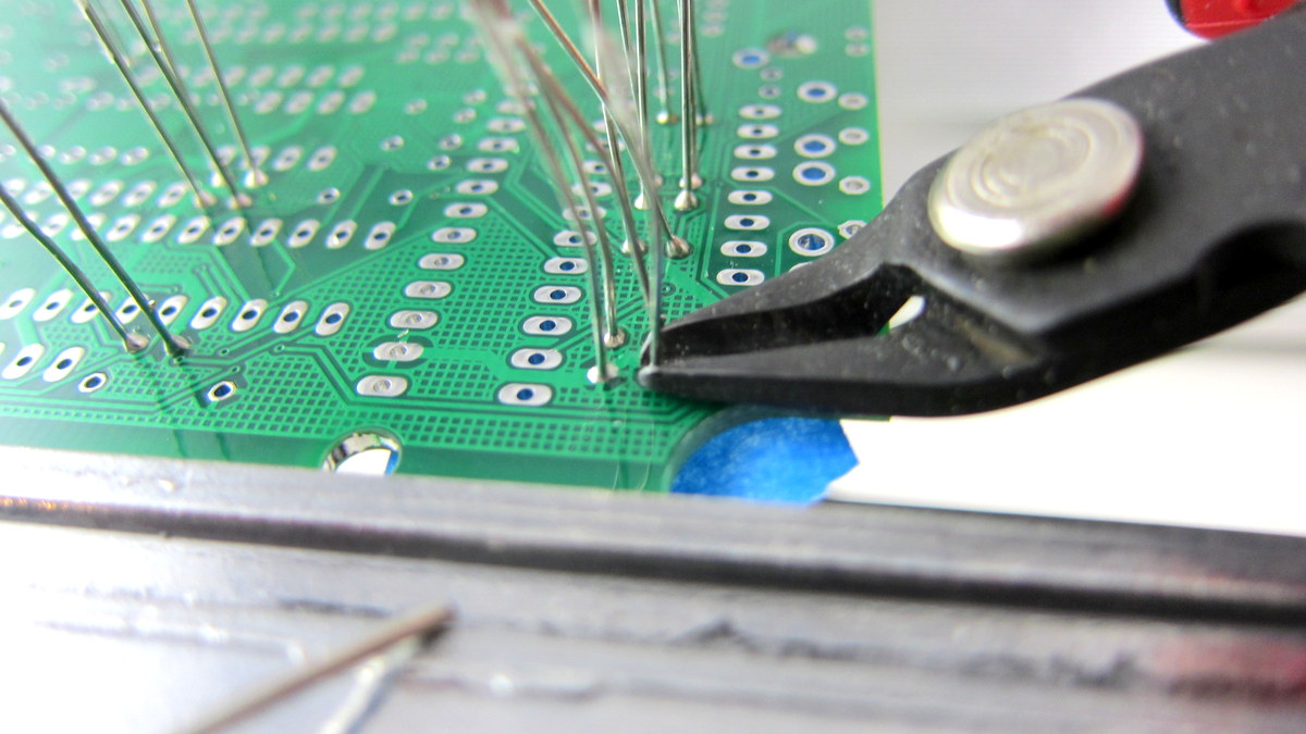
To solder a resistor, bend its two leads as close as possible to the resistor body, then insert it to the PCB holes. To increase productivity, I usually insert multiple components at once, and use painter’s tape to fix them in place (see image on the left). You can use as many pieces of tapes as you need. Then flip the PCB and solder all leads. This way you can solder multiple components in one pass and reduce the number of times to flip the PCB. Make sure your soldering iron is hot, and can easily melt and reflow solder without applying much pressure. After soldering, use a diagonal cutter to clip the leads just above the end of the solder joints. |
|
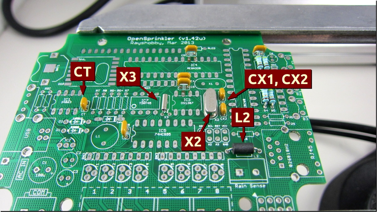
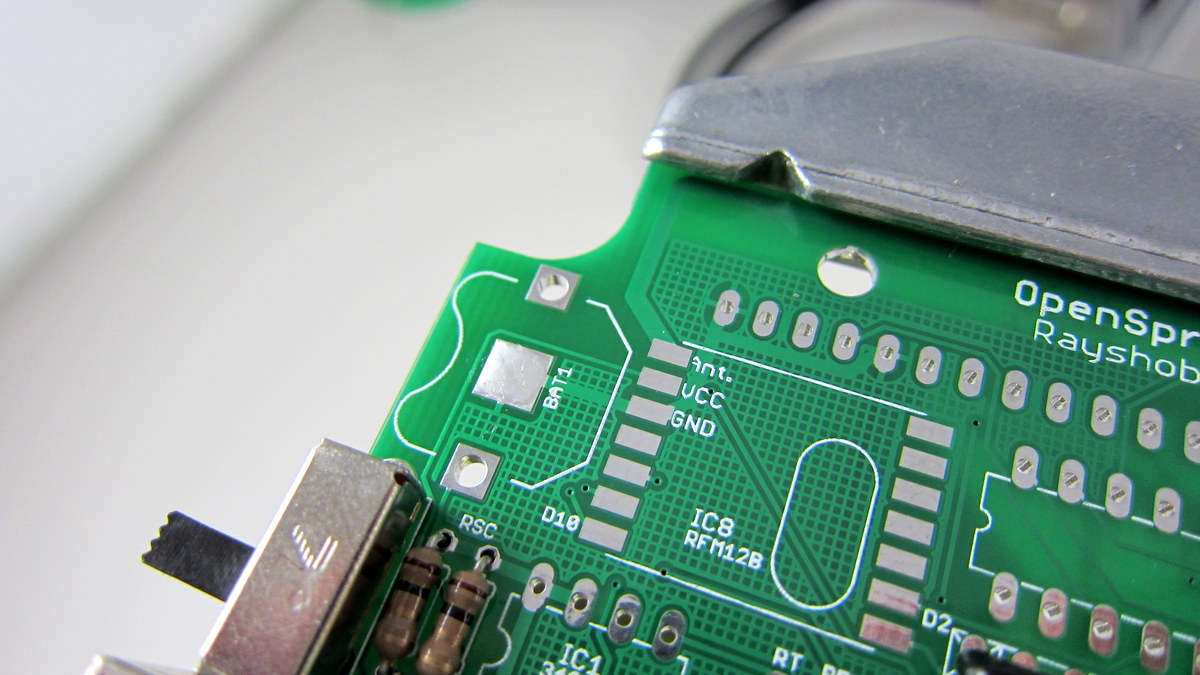
Next, solder two crystals: X2 (25MHz, oval, two pins), and X3 (32.768KHz, small cylinder shaped, two pins). Check the image on the left to see where they are located. These components are non-polar. Note that X1 should be left empty (it is reserved to recover the mcu in case you accidentally programmed its fuse bits wrong). Please DO NOT solder the 25MHz crystal onto X1 (that would caused the Ethernet controller to stop working). Update: if your PCB is dated 05/2013 (check the silkscreen at the top of the PCB), crystal X3 should be oriented upright, which is different from the picture on the left. Then solder three ceramic capacitors: CT (100pF), CX1 and CX2 (18pF, on a strip together). These three capacitors look very similar, but if you reader carefully, you will see that CT is labeled 101, while the other two are labeled 18J. Also solder L2, a ferrite bead. It’s cylinder shaped, and non-polar. |

|
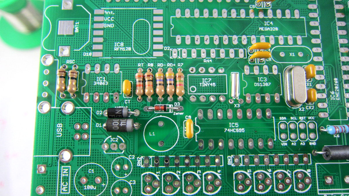
Now you will solder a bunch of resistors. They are listed below:
Click the image on the left to see where they are located. |
|
Now solder three diodes: D1 (R3000, biggest among the three), D2 (1N5819), and D3 (5.6V zener, smallest among the three). They are all located on the left side of the PCB. To solder a diode, use pliers to gently bend the two leads to 90 degrees. Important: diodes have polarity, allowing current to flow only in one direction. Identify the end with a white stripe (the negative lead). This stripe should match the silkscreen on the PCB. Compare yours with the image on the left. |
|
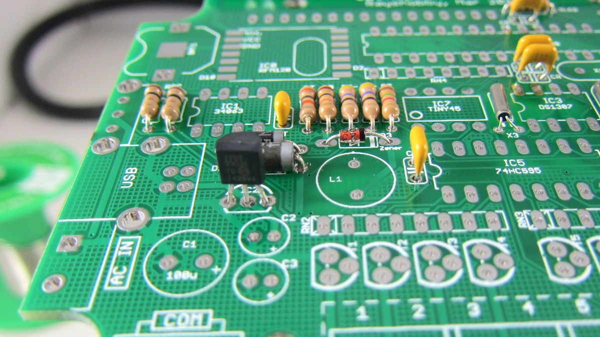
Next, solder IC2, an MCP1702-33 linear regulator from the IC bag. It has 3 pins and is shaped like a half cylinder, similar to a transistor. Note: be careful not to confuse it with the triacs from the screw terminal bag. Align it such that the semi-circle matches the PCB silkscreen. Then solder the three leads at the back of the PCB. |

|
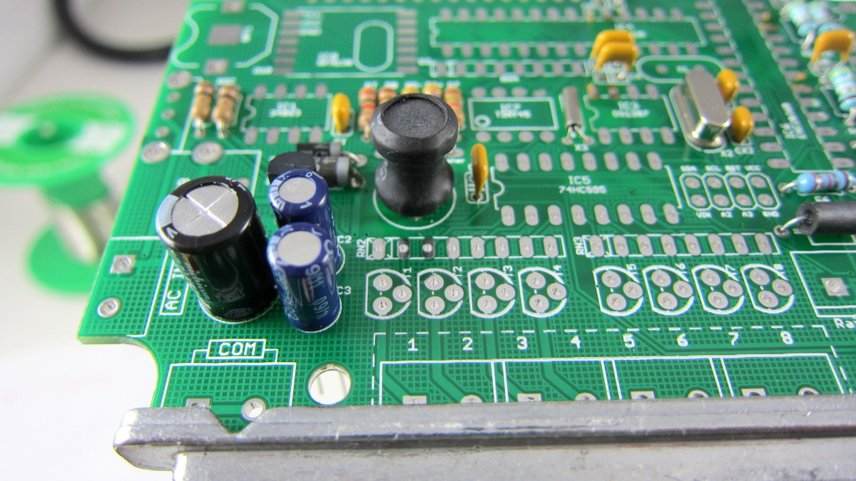
Next, solder L1, a power inductor. It is dark, cylinder-shaped, and non-polar. Try to tilt it towards the bottom of the PCB, so that later it won’t get in the way of the LCD.
Moving on, now solder C1, a 100uF electrolytic capacitor. Its a relatively large component. Electrolytic capacitors are polarized: make sure the longer (positive) lead goes into the hole marked with +. To double check, there is a white stripe on the capacitor body which points to the negative lead. |
|
Similarly, solder C2 and C3, two identical 220uF electrolytic capacitors. Note that in some packages these two capacitors look similar to the 10uF capacitor which you will solder next. So please read the label to distinguish them. Also, pay attention to the polarity and remember the longer lead goes into to + hole. Compare yours with the image on the left.
Now solder C6, a 10uF electrolytic capacitor located at the upper right corner of the PCB. |
|
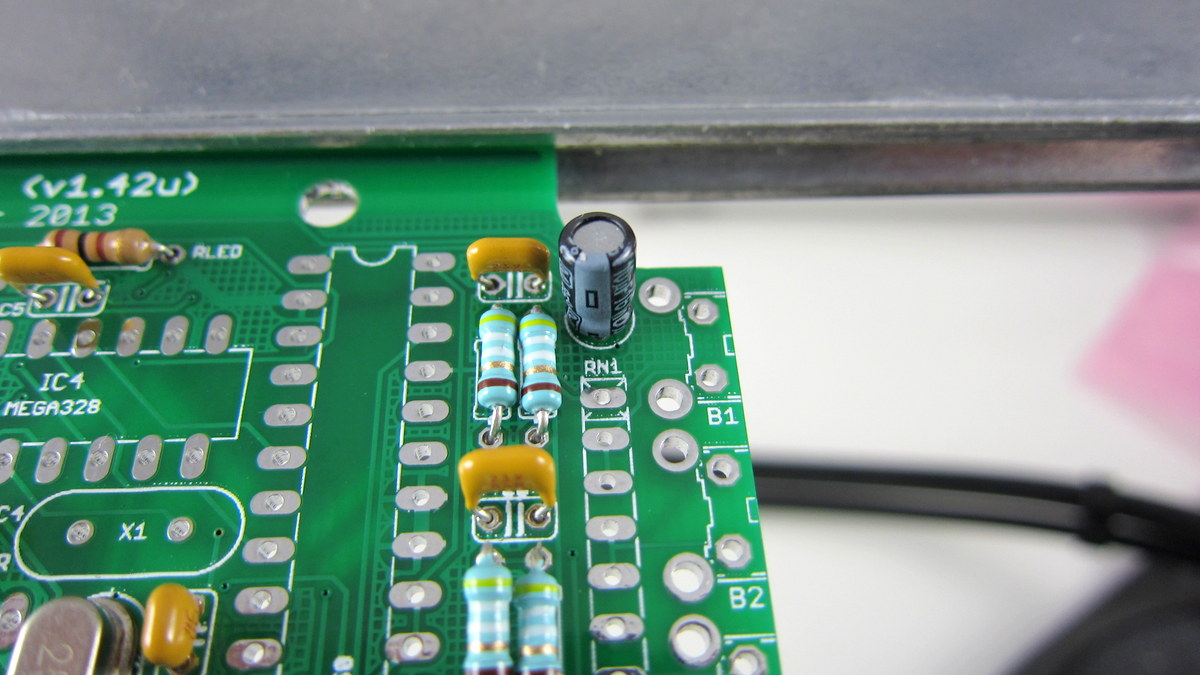
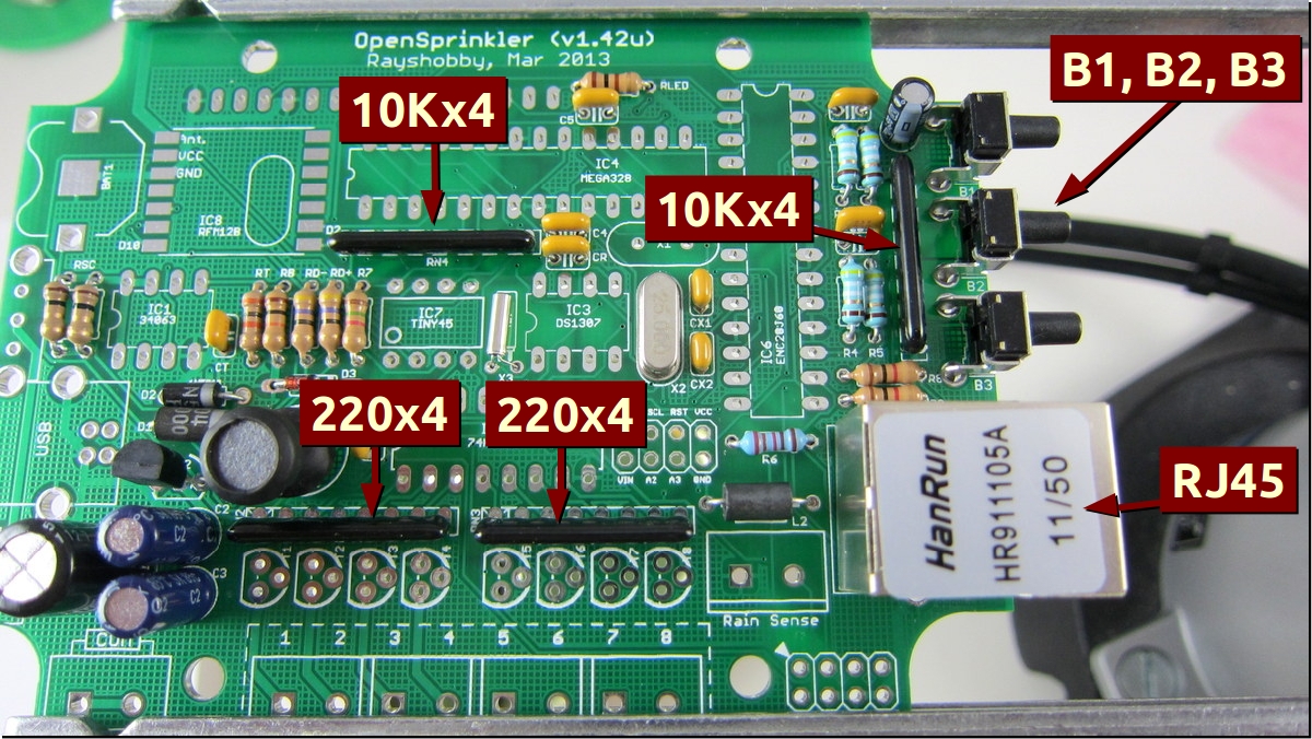
In the next step, solder four resistor arrays: RN1, RN4 (two 10Kx4), and RN2, RN3 (two 220×4). Each resistor array has eight pins and consists of four identical isolated resistors. It is symmetric so you can insert it in either direction. Because these four look very similar, you must identify them by reading the labels. For example, 10K array should read ‘L83S 103 xxxx’, and 220 ohm array should read ‘L83S 221 xxxx’. Make sure you will not mix them up. Double check yours with the image on the left.
Now solder three right-angle push-buttons: B1, B2, B3, as well as the RJ45 Ethernet connector. These are located on the right edge of the PCB. When inserting the RJ45 connector, watch out the pins and make sure all of them will go through the holes. |
|
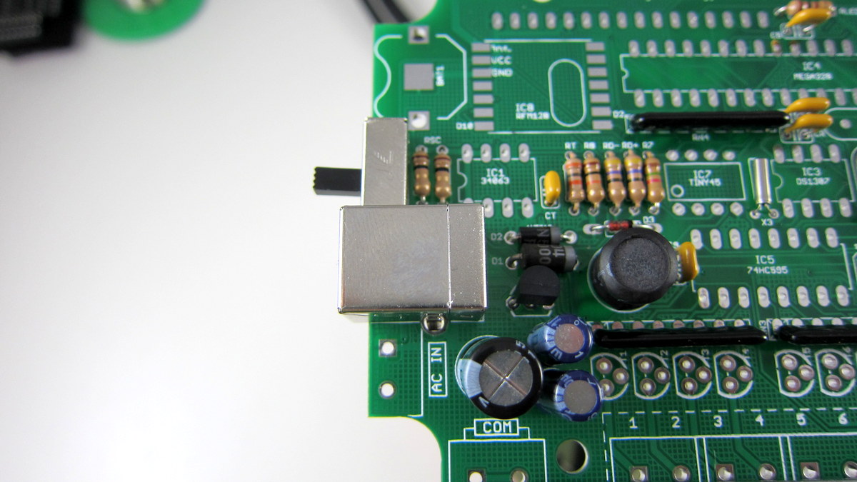
Now move to the left side of the PCB, and solder the USB connector, as well as the Slide Switch. The pins on the slide switch might be spaced slightly larger than the PCB holes. If this is the case, slightly bend them together before inserting it into the PCB. |
|
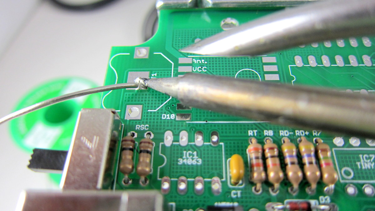
Now solder the coin battery holder. To begin, use a small amount of solder to tin the PCB pad. This is important to ensure the battery has good contact with the pad. The image on the left shows the result of tinning. It should be a very thin layer. Now go ahead and solder the battery holder. |
|
Now solder all IC sockets (from the IC bag). Be careful when inserting the IC sockets: make sure all socket pins go into the PCB holes correctly, and no pin is left out or twisted.
Every socket has a small notch (see the picture on the left) to help identify the orientation. This notch should match up with the silkscreen on the PCB. |
|
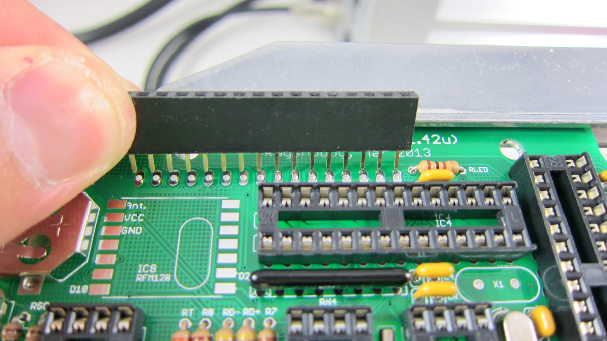
Next, solder the 1×16 female pin header for the LCD. This pin header is located at the top of the PCB. |
 |
Now take out the LCD and the 1×16 male header. Solder the male header onto the LCD. The easiest way to do so is by making use of a breadboard to hold the pin header during soldering. |
|
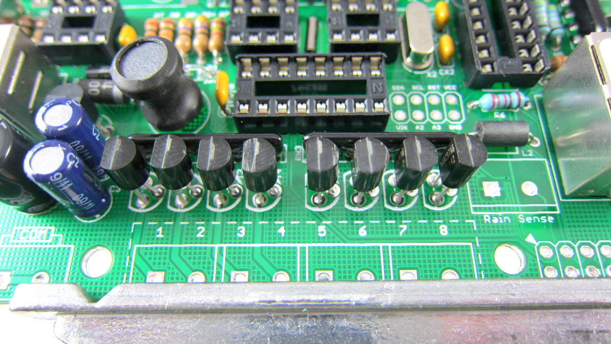
Next, solder the eight triacs (MAC97) T1-T8. Use your hand to bend the middle pin slightly backward, so that you can easily insert it to the PCB holes. Watch out the orientation of the triac. |
|
The last step of soldering is the screw terminals and the zone expansion connector. Take out the screw terminals. Solder the AC In, COM, and station terminals S1-S8. Each terminal consists of two pieces. You should solder the board piece (with right-angle pins), the other piece will be plugged in later.
Then proceed to solder the 2×4 right-angle male header. This is used to connect the main controller to zone expansion boards. Voilà, you are all set with the soldering part! Check your circuit board with the image on the left. |
Part 2: Testing
|
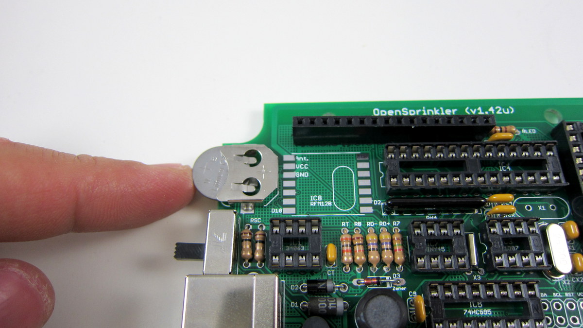
In this section, you will test the circuit and make sure it’s functioning. Start by inserting the CR1220 coin battery. The battery is included either in the IC bag or the terminal block bag. |
|
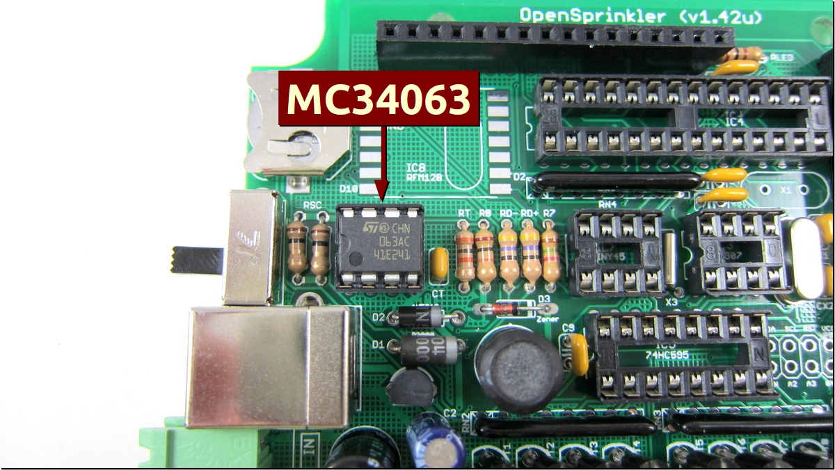
Now insert IC1 into its socket. This is a MC34063 switching regulator. Bend its pins slightly inward on a hard flat surface. While inserting, make sure no pins are left out or twisted. Make sure that its notch matches the notch on the socket. Refer to the image on the left.
Double check that you have inserted MC34063, not the other two ICs (DS1307 or ATtiny45). At this point, you should only have IC1 inserted. Leave the other ICs out. This can help reduce the possibility of damage in case something goes wrong with your power supply circuitry. |
|
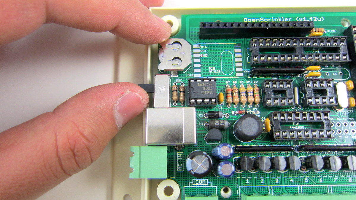
Test the power supply section. First, slide up the power switch to turn it off. Then, insert the two wires from your 24VAC sprinkler transformer to a 2-port screw terminal piece. AC power has no polarity, so it doesnt matter which wire goes to which port. Tighten the terminal screws, and plug the piece into the AC IN terminal. Make sure you’ve plugged into the AC IN terminal, not the COM terminal (which also accepts a 2-port piece). Important: use a multimeter to measure the AC voltage between the two transformer wires. Make sure it’s no more than 29VAC. |
 
|
Voltage check: use a multimeter, measure the DC voltage between VIN and GND (+5V). These two pins are located in the 2×4 pinout area on the left of the RJ45 connector. Click the image to see where they are located.. The reading should be around 5.0, and anywhere between 4.8V to 5.2V is acceptable.
Next, measure the DC voltage between VCC and GND, should be around 3.3 (anywhere between 3.2V to 3.4V is acceptable). It is crucial to check and ensure these voltage readings are correct, otherwise your controller may malfunction or get damaged. After testing the voltages, power off the controller and unplug the AC IN terminal. |
|
Now you can populate all ICs to their sockets: IC3 (DS1307) is the RTC, IC4 (ATmega328) is the MCU, IC5 (74HC595) is the shift register, IC6 (ENC28J60) is the Ethernet controller, and IC7 (ATtiny45) is the pre-programmed USBtiny ISP.
To insert an IC, bend its pins slightly inward on a hard flat surface. While inserting, make sure no pins are left out or twisted. Finally, check your PCB with the photo on the left to make sure all ICs are inserted to the correct position. You are all set! Take a moment to appreciate your work! |
Part 3: Project Case
 |
Now you can assemble the project case. First, check the case, including the top, bottom, four case screws (long, #4 3/8″) and four PCB screws (short, #4-40 3/16″). |
 |
Fix the PCB to the case bottom using the four short screws. Insert the LCD to the 1×16 female header on the PCB. Now you can install the plastic cover. Then carefully press the cover down and make sure it is in good contact with the bottom. |
 |
Use a screwdriver (electric screwdriver are better at this) to install the case screws from the bottom of the case. |
 |
That’s it! Note that the back panel of the case is wall mountable.
Some notes about using the controller:
|