 |
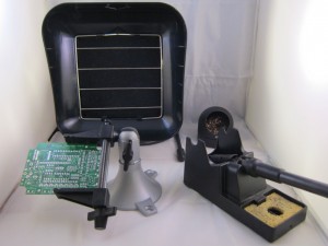
To begin, place the PCB onto a a vise, and turn on the soldering iron. (Optional: use a fume extractor to help remove solder fumes).
Remember: all images on this page are ‘clickable’, in case you want to check full-resolution details.
|
|
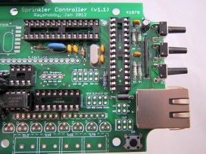
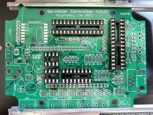
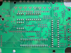
Insert and solder all IC sockets (from the IC bag). Be careful when inserting the IC sockets: make sure all legs go into the PCB holes correctly. Double check before you start soldering.
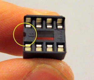
Every socket has a small notch (see the picture on the left) to help identify its orientation. This notch must match up with the silkscreen on the PCB.
Note: due to a manufacturing glitch, the vias are not covered by solder masks. When soldering, watch out the vias and avoid shorting a solder pad with nearby vias. Increase your soldering iron temperature allows the solder to flow better and can help.
|

|
Now we will build the power supply section, the components of which are all located at the lower-left part of the PCB.
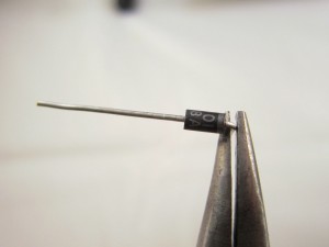
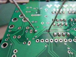
First solder D1, a 1N4001 diode. It looks similar to D2, so be sure to read the label on the diode. Use pliers to gently bend the two legs to 90 degrees. Note that diodes have polarity, allowing current to flow only in one direction. Before inserting it to the PCB, identify the end with a white stripe (the negative leg). This stripe should match the silkscreen on the PCB. Again, when in doubt, click on the images to get a full-resolution view. |
|
On the back of the PCB, bend the legs to the side, so that you can flip the PCB and the diode will stay in place. Solder both legs.
To make sure the component lies tightly on the PCB, you can solder one leg first, then keep the soldering iron on the joint while pushing or pulling the component towards the PCB. Once it’s in place, proceed to solder the other joint.
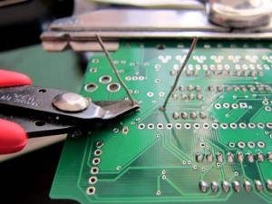
Next, use a diagonal cutter to clip leads just above the end of the solder joints. |

|
Follow the same method to solder D2 — a 1N5819 (or SB160) Schottky diode, as well as D3 — a 1N4148 diode. Again, be careful with the polarity of diodes.
Now solder the green LED. LED is a diode, so it also has polarity. The longer leg of the LED is positive, and should go into the PCB hole marked with + as shown in the photo on the left.
|
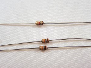 |
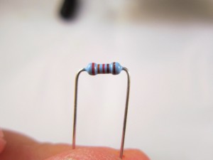
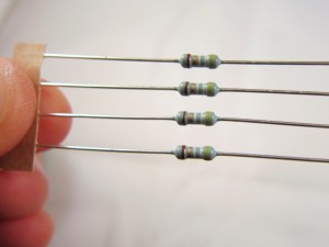
Next, solder R1, a 1K resistor. In the package you will find three tiny resistors with similar looks: one has a red ring (1K) is what you should solder here; the other two have an orange ring (10K) that you will need later. If you have difficulty telling them apart, use a multimeter to measure the resistance. Resistors are non-polar, so you can insert them either way.
|
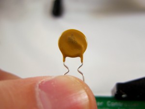 |
Now solder the PTC fuse. I’s a yellow, disc-shaped component used for current protection. If you don’t want current protection, solder a wire across the fuse to disable it.
|
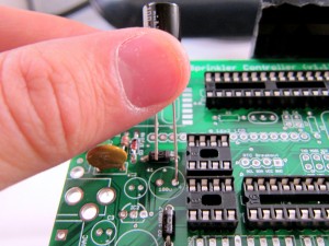 |
Moving on, now solder C1, a 100uF (50V) electrolytic capacitor. It’s a relatively large component. Electrolytic capacitors are polarized, so make sure the longer (positive) leg goes into the hole marked with +. To double check, there is a white stripe on capacitor body which points to the negative leg.
Similarly, solder C2 and C3, two identical 220uF electrolytic capacitors. Again, longer leg corresponds to + hole.
Update: in some packages, C2 and C3 are replaced by smaller, 100uF capacitors.
|
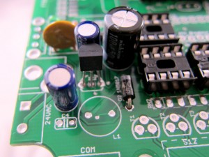 |
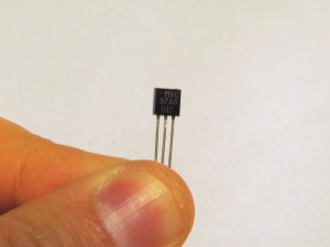
Now solder IC2, a MCP1700-33 linear regulator (from the IC bag). It has 3 pins and is shaped like a half cylinder, similar to transistor. Note: be careful not to confuse it with MAC97, which are triacs from the terminal block bag.
Align it such that the semi-circle matches the PCB silkscreen. Then solder the three legs at the back of the PCB. |
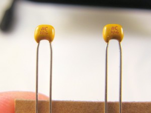 |
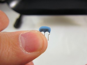
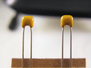
Next, solder C4, a 0.1uF ceramic capacitor. In the package you will find two sets of ceramic capacitors: one set contains a strip of five 0.1uF ones; the other contains two 18pF ones. If you look closely, the 0.1uF one should read ‘104’. Ceramic caps are non-polar, so insert them any direction you want. |
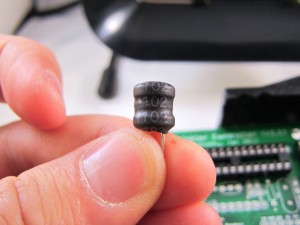 |
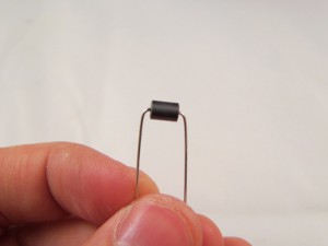
Now solder L1, a 1000uH inductor that reads ‘102’. Inductors are not polarized, so insert them any direction you want. |
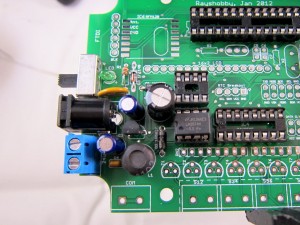 |
We are almost done with this part. The last step is to solder J0 (terminal block), J1 (power barrel), and J2 (slider switch).
|
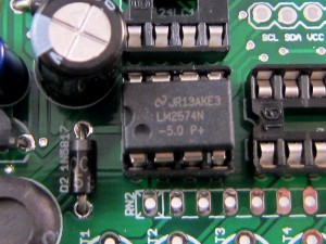 |
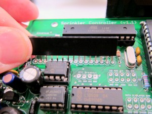
Insert IC1 into its corresponding socket. This is an LM2574N switching regulator, which outputs a regulated +5.0V from high voltage input. Make sure that its notch matches the notch on the socket. Refer to the picture on the left.
Double check that you have inserted LM2574N, not 24LC128 which has the same number of pin counts.
|
|
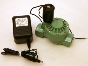
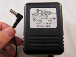
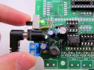
Now it’s time to test the power supply section. First, slide up the power switch to turn it off. Then, insert the 24VAC sprinkler transformer. Either J0 (terminal block) or J1 (power barrel) can provide input power, and the choice depends on what sprinkler transformer you have. If the transformer comes with a power plug, insert it to the power barrel; otherwise, if it has two terminal wires, insert to the terminal block and tighten the screws.
Slide down the power switch, you should see the green LED lit.
Important: (although this is unlikely) if anything burns or smokes, immediately turn off power. Check to see if there is any component visibly damaged. If you can’t figure out the problem, post a message in the forum and we will help you.
Tip: For quick testing, you can substitute the 24VAC adapter with any DC adapter with +6V or above output voltage. For example, a 9V DC adapter can be used for testing. The LM2574N switching regulator can accommodate a wide range of input voltages. |
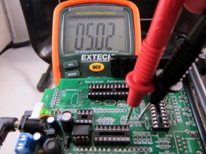

|
Voltage check: use a multimeter, measure the voltage between GND and VIN in the pinout area. It should read about +5V. This is the voltage supplied to the LCD.
Next, measure the voltage between GND and VCC, whic should be around +3.3V. This is supplied to the MCU and Ethernet controller.
Important: It’s crucial to check and ensure these voltage readings are correct, otherwise your controller may not function properly.
After testing the voltages, disconnect the power.
Heads-up: During reprogrmaming, when the controller is powered solely by the FTDI programmer, the LM2574N regulator may feel unusually hot. This is ok. Normally the controller should be powered by 24VAC and the regulator should feel mildly warm.
|

