OpenSprinkler Switching Other Devices
Check this blog post for a simple way to use OpenSprinkler to control remote power sockets.
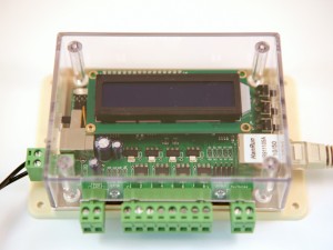
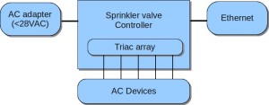
With some modifications, OpenSprinkler can be used to switch other electronic devices via the same web interface. In essence it is really a general-purpose development board that has a microcontroller, Ethernet controller, LCD, buttons, output drivers and terminal blocks to control devices. The on-board triacs can be used to switch other AC devices, so long as the voltage required by these devices fall below 28VAC. The limit is due to the fact that the controller uses a single power supply design, and the switching regulator’s maximum input voltage is 40VDC.
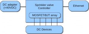
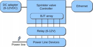
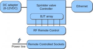
Besides, the triacs can be replaced by MOSFETs/transistors to switch DC devices, as long as the DC input is below 40VDC. If you need to switch high-voltage devices, such as power line devices, you can use the controller to switch 24VAC relays, and the relays will in turn control high-voltage devices. Alternatively, you can use the controller in conjunction with an RF transmitter to send switch signals to a remote power socket. This provides an easy and safe way to control power line devices.
The diagrams below show how various devices can be connected and switched by controller, allowing them to be scheduled from the same web interface. I’ve also included a couple of demonstrations that I quickly put up together as proofs of concept. If you have thoughts and suggestions, be sure to drop me a line. Thanks!
Example 1: Switching DC Light Bulbs
Here I replaced the triacs with MPSA14 darlington transistors in order to switch DC components. The replacement is very simple because the triac pinouts match the transistors exactly, so they are inserted the same way into the PCB. I then bought a number 12VDC 4-Watt landscape light bulbs and connected them to terminal blocks. Voila, I have a web-controlled light bulb array! Maybe use it to light up Halloween pumpkins?
Caution: Your transistors must have sufficient current and voltage ratings to drive the DC output. For example, if your device works with 12V DC and draws 500mA when turned on, the transistor’s maximum voltage and current ratings must be at least 12V DC and 500mA.
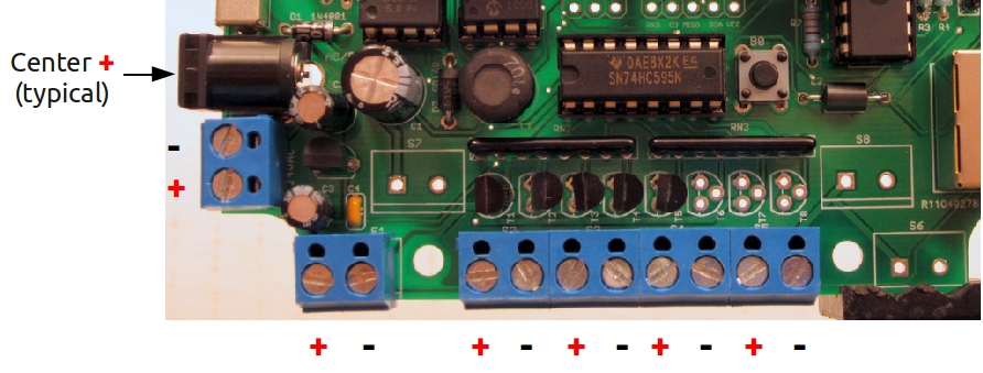
Caution: Since DC has polarity, you have to distinguish between the positive and negative pins. For light bulbs this doesn’t matter, but in general you should pay attention to polarity. I’ve marked the image below to indicate positive and negative leads. The input power is protected by diode D1, so if you happen to connect the power incorrectly it shouldn’t blow up the circuit. However, the driver ports are not protected, so make sure you are connecting your devices in the right direction! (This diagram is only for OpenSprinkler v1.0! For other versions please refer to the circuit board design).
Finally, I did a quick demo to show that it’s possible to output PWM signal (through the shift register) to the DC components to provide analog control, for example, adjusting the brightness of the light bulbs.
Example 2: Switching Power Line Sockets using Relays
I didn’t put up a demo for this, but the idea is similar to example 1, except the relay coils will be replacing the light bulbs. Part of the reason I didn’t put up this example is that I don’t want to mess with high voltage. That’s why I found the next example is more practical, as it completely shields me away from power lines.
Example 3: Switching Power Line Sockets using Remote Controlled Switches
Update: check this blog post to learn a simple way to use OpenSprinkler to control remote power sockets.
I looked around Amazon.com and found these remote controlled switch sockets that works great and are really cheap. The package comes with a remote control and three sockets that can be individually turned on or off. After studying the remote control a little bit, I found it consists of a encoder (HS2262A) and a simple 434MHz RF transmitter. When you press a button, the RF signal is received at the socket, decoded, and used to control a relay that turns power on or off. This is great for controlling power line devices — all I have to do is to hacking the remote control to interface with my controller, no danger of touching high voltage!
The details are documented on this blog article. Long story short, on most remote controls, each button sinks a MCU pin to ground, so it’s very easy to simulate the button press by using a NPN transistor that serves as current sink. However, on this particular remote, each button connects +12V to the encoder pin, so I need a current source. This turns out to be not very difficult — it just requires an addition PNP transistor coupled with the NPN transistor to provide source. In any case, my blog article explains the details. Demo video is attached below.
