Recently I received a request to customize OpenSprinkler for a 12V DC external relay board. It turns out to be relatively easy to do. Since it may be useful for other folks, I am writing a post here to briefly describe the modifications. First of all, the relay board has built-in opto-couplers and flyback diodes. It is designed to work directly with microcontroller pins. This particular relay board I received is an active low type. This means normally the relay control pin is pulled high; when the control pin is set low by the microcontroller, the relay will be activated. So before you go ahead and make changes, make sure to find out the type of your relay board.
OpenSprinkler can run on 12V DC power supply without any modification. As long as you keep in mind the polarity, it should work right away. Even if you connect the power supply in the wrong direction, it shouldn’t cause any damage because there is a protecting diode D1 that prevents reverse polarity. The only modification I needed to do is to replace the triacs (used to drive AC solenoids) by NPN transistors. Any common NPN transistor is fine. For example, 2N3904. The remaining step is to connect the station wires to the corresponding relay control pins.
The way it works is that normally the shift register outputs low. So all NPN transistors are turned off, and the collectors are pulled high by the relay board. When a station is open, the shift register pin outputs high, turning on the corresponding NPN transistor, and driving its collector low (to ground). This in turn activates the relay. That’s it.
Here is a video showing the relay board in action. The OpenSprinkler running a self test that turns on each station for 3 seconds.
It is also possible to use the NPN transistors to directly drive the relays. However, in this case, you need to add an additional flyback diode (between the collector of the transistor and the +12V line). The flyback diode is important to protect the transistor under inductive load. To accommodate this, I am planning to add PCB holes for these diodes in the future, which will make it easy to solder these extra components.
Hi, I am excited to announce the arrival of SquareWear — a new open-source microcontroller board I designed for wearable electronics projects. First off, here is an introduction video:
Background. So why did I work on this? Well, last year I helped my school with several wearable electronics workshops. They were great success: the students had a lot of fun sewing LEDs and sensors onto clothes, and many women students came to attend the events. We used Lilypad Arduino, which is a popular microcontroller board designed for wearable computing projects. It’s a very nice design, but using it for a 40-student workshop presented a few challenges. First is the cost. Lilypad itself costs about $20, which is ok. But to program it, you need to get an external FTDI cable, which costs another $15. We want students to take the gadgets with them after each workshop. But since we had a small budget, we couldn’t afford to buy one set for each student. So we had to let every 2 students share a set. Not everyone was happy about it. Second is FTDI driver issues. You would think this is easy, but it turned out that at the beginning of each workshop, we had to spend 30-40 minutes just to help everyone install FTDI drivers. Students were using all sorts of operating systems and having all sorts of unexpected problems. Some were even using pre-beta version of Windows 8 64-bit… Anyways, it was not fun. What I really wanted is a board that does not need any driver installation. Whether you are using Windows, Linux, or Mac, the system should recognize the device automatically. Next is the number of external components required. Many students started designing beautiful LED patterns that involve a lot of parallel LEDs, only to find out later that the LEDs looked really dim. Why? The standard microcontroller pin can only source or sink 25mA of current. If you have a string of 20 LEDs, they will not look bright because of the current limit. The better solution is to use a transistor or mosfet to allow switching higher amount of current. Because switching LEDs is very common task in wearable electronic projects, it would be nice to have mosfets as built-in components on the board. Similarly, some students wanted to include push-buttons to their projects, but the push-button on Lilypad is only for reset, not for general-purpose function. Lastly, it would also be nice to have an on-board coin battery option, because coin batteries are cheap and easy to find in local stores.
So these experiences motivated me to develop my own wearable electronics board, and here comes the SquareWear!
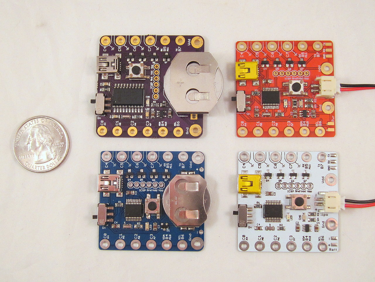
Features. The name SquareWear comes from its shape: a 1.6″x1.6″ square. Credits should be given to my colleague Andrew who came up with the name. Officially it’s Square-Wear, but it could also be Square-Ware, either way you like. I made it with a few different colors and two battery options: a coin battery version, which runs on a built-in CR2032 battery, and a li-po version, which runs on an external li-po battery. Each board has a built-in USB port, which is used for multiple functions: programming the microcontroller, USB serial communication, recharging battery (li-po version), and providing power directly. No external FTDI cable any more! The microcontroller is pre-flashed with Microchip’s USB HID class bootloader, which requires no driver installation, whether you are using Windows, Linux, or Mac. In addition, SquareWear has four power sink pins wired to on-board BS170 mosfets. These four pins support up to 500mA load, which makes them suitable for driving many parallel connected LEDs. Using these power sink pins, your LEDs will look nice and bright. Lastly, there is an on-board push-button that you can use as a general-purpose button. In sum, I designed all these features to make SquareWear a low-cost, all-in-one solution for wearable electronics projects. You can get started right away without having to worry about external components or programmers.
Programming. SquareWear runs Microchip PIC18F14K50 microcontroller. What? It’s not based on Arduino? Why? Well, let me explain. The project started as I was shopping around for different microcontrollers. My friend Christian recommended me to look at PIC. Around the same time I also started designing my own wearable electronics board. At one point I realized I should build the wearable microcontroller board using PIC, because this will be a good motivation for me to learn PIC programming. I chose 18F14K50 to begin with, because it’s among the lowest-cost microcontrollers that have built-in USB support. As I got more familiar with it, I started liking it more and more. It has a decent amount (16KB) of program memory space, not a whole lot, but sufficient for most entry-level wearable electronics projects. It has a decent number (12) of i/o pins, again, not a whole lot, but enough to fit all pins on a small PCB without wasting any. Most importantly, it has Microchip’s USB bootloader and serial communication support. So this naturally became my choice for SquareWear.
Another reasons I went with PIC is that its programming environment – MPLAB X – is a fully-featured cross-platform IDE. It has all the features of a standard IDE, such as code navigation, context aware code completion, debugging, and support for project files and library files. I like using standard IDEs. I think Arduino is great for beginners, but there is no code navigation and completion, and debugging is only possible in printf style. If you are serious about learning to program, you should start using professional tools. I would like to use SquareWear as a way to introduce programming to students, and I think it’s important to get them exposed to standard tools right in the beginning. It will require a slightly higher learning curve, but it’s absolutely worthwhile.
SquareWear Library. I spent quite some time writing the SquareWear Software Library, making it simple to use just like the Arduino. It abstracts away a lot of low-level programming details. I also included several features, such as software PWM, timer interrupt, button interrupt, software reset, which I feel are very useful for wearable projects. Take a look at the SquareWear Demos and the Programming Reference to find out more.
One downside with using 8-bit PIC is that its compiler C18 is a C compiler, that is, not C++. So there is no object-oriented programming, which may appear disappointing. But it’s not a show stopper: we all like the benefits of object-oriented programming, but there are tons of microcontroller projects that are written in plain C style perfectly fine. Particularly with respect to wearable projects, they are typically quite simple. There is no need to use objects, inheritance, function overriding, and all those good stuff. So no need to panic because of the lack of C++.
The last thing to mention is that just like my other projects, SquareWear is completely open-source: the hardware design and software code are all available on GitHub. Beyond wearable electronics projects, SquareWear is also a great little tool for general prototyping need, like interfacing with sensors and actuators. Give it a try and hope you like it!
OpenSprinkler’s 1-year anniversary! Yes, on Oct 9 last year, the OpenSprinkler project got posted on Hackaday and became known to the world for the first time. A lot of updates have happened during this past year. The hardware has gone through four cycles of changes, and the latest version is 1.4. From August 2011 we have started producing the surface mount version of 1.4, making it easier to manufacture and assemble the kit. The software has also been substantially improved. Many user-requested features have been included. I am proud to say that at this moment OpenSprinkler is probably the best Internet-based sprinkler timer with its price and the functionality it provides. I am hoping that in the upcoming years it will start making a positive impact on the technology innovation in consumer-level sprinkler products.
To honor the 1-year anniversary, all orders placed on Oct 9 (today) and 10 will receive a 10% discount. If you have ever considered buying OpenSprinkler but hasn’t made up your mind, there is no better deal than this!
Statistics wise, most OpenSprinkler orders came from the United States, which is not a surprise since we are based in the US. But OpenSprinkler has also reached places outside of the US. So far it has reached close to 30 countries. Here is an un-ordered list: Germany, Netherlands, Australia, South Africa, France, Bulgaria, Spain, Slovakia, Canada, UK, Finland, Portugal, Hungary, Singapore, Belgium, New Zealand, Italy, Turkey, Greece, Peru, Switzerland, Cyprus, Ukraine, Denmark, Estonia, Poland, Austria. I have also marked them on a world map, to give you a better visual:
I want to take a moment to thank the open-source movement. I am a strong supporter for open-source hardware and software. I believe open-source is important for pushing technology innovation and for promoting and implementing new ideas as quickly as possible. Unlike large-scale closed source products, open-source products are often started with a low budget and produced in small batches. We typically assemble kits on the level of a couple hundred per batch. This is how we can quickly update the design, fix bugs, introduce new features, and shorten the overall design cycle. If a particular design didn’t work out, we can simply abandon it and move on. There is little risk of losing big investment money. Also, having a project open-sourced makes it possible for the public to scrutinize the design, identify issues, contribute to the project, and build new projects. As a college educator, I am keen at understanding the underpinnings of how electronic products work, but more than that, I am keen at giving out the knowledge that I know.
Update: OpenSprinkler 2.0 or above uses a different switching regulator and does not require additional resistor any more. The information below is only relevant to OpenSprinkler 1.x.
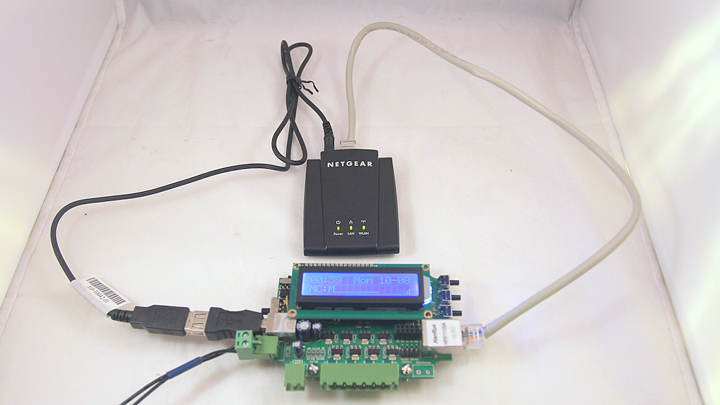
As you know, OpenSprinkler uses a single 24VAc sprinkler transformer to power both the circuit and the sprinkler solenoids. Frequently people are using a WiFi adapter together with OpenSprinkler to provide wireless Ethernet connection. So how about using the same transformer to also power the WiFi adapter? Ah ha, good question. This turns out to be possible and quite easy to do!
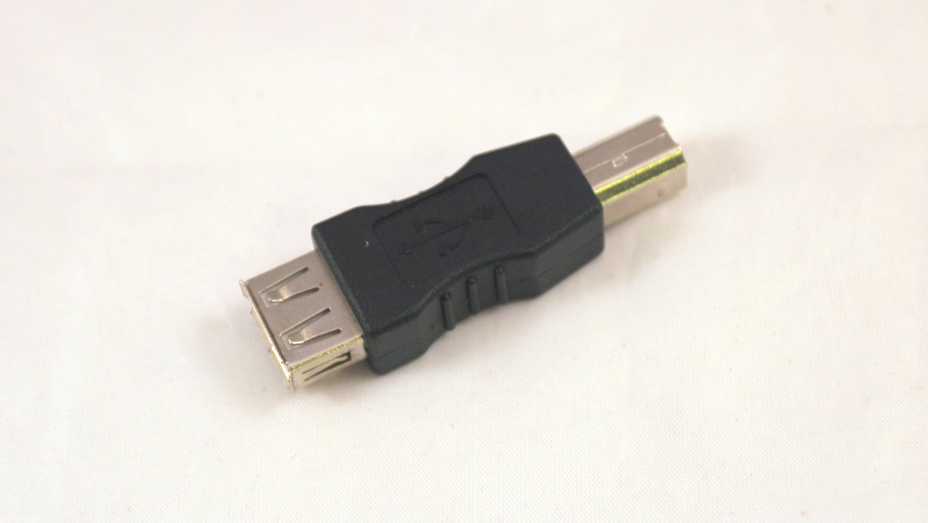
The basic idea is that many of these WiFi adapters (such as the popular NetGear WNCE2001) can be powered using an attached USB cable. One end of the cable is a USB Male A connector, and the other end is typically a 2.5mm power jack that goes into the adapter. Since OpenSprinkler has a built-in USB port (which is connected to the +5V output of the 34063 switching regulator), it can be used to directly power the WiFi adapter. However, OpenSprinkler’s USB connector is a Female B type, so the trick to make this work is to throw in a USB Female A to Male B converter, as shown in the picture below:
You can get this converter from Rayshobby Shop or at online retail stores.
Hold on one second, this is not the only thing you need to do. You also have to solder an additional 1 ohm resistor to the circuit board. The reason is that these WiFi adapters are quite power hungry: I measured that the NetGear WNCE2001 draws about 300-400mA current during operation. On the other hand, OpenSprinkler (by default design) outputs about 330mA current on its +5V output, of which 180mA will have to power the mcu and Ethernet controller. So we need to increase the current output. Fortunately this is not too difficult to do. The trick is to reduce the resistance of Rsc — current limiting resistor for the 34063 switching regulator. According to 34063’s datasheet, the maximum output current is 0.33/Rsc. So if we put two 1 ohm resistors in parallel, Rsc is effectively 0.5 ohm, and hence the maximum output current increases to 660mA, enough to power both the circuit board and the WiFi adapter. Also, OpenSprinkler v1.3u and v1.4 have already designed a spare slot for the parallel Rsc, so it’s pretty easy to make the modification.
You can reduce Rsc even further to provide better safety margin. 34063 supports maximum output current of 1.5A. To do so, you can keep putting more 1 ohm resistors in parallel until you reach the desired resistance. The reason to use multiple 1 ohm resistors is because it’s lowest value common resistor. Anything below 1 ohm will have a big price jump.
Again, if you are interested in trying this, you can get the USB converter from Rayshobby Shop. We will also throw in a couple of 1 ohm resistor free of charge!
I had the urge to send this out a week ago, but I was holding on to it because I had to hear some feedback, suggestions, and issue reports from the initial users. Now I am ready to spread the words:
As always, the first question I need to answer is: what’s new in this version? Here is a list of highlights:
• New features:
Custom station names: each station can have a custom name up to 12 letters long.
Per-station master operation control: each station can individually activate the master station.
Run-once program: similar to the manual override feature on some sprinkler timers.
Station delay time, and master on/off adjusted time: fine tune station turn-on and turn-off time.
Water level/percentage: globally scales water time up and down based on local weather conditions.
Automatically reconnect: improves reliability on unreliable networks.
Support for RTC and automatic RTC detection: keeps time running even when power or network is lost.
Full range of time zones: living in Nepal? No problem.
• Improved features:
Program now has an ‘enable’ flag which allows you to enable or disable each program individually.
Improved Graphical Preview feature, which shows each station’s name and scheduled on/off time.
So this is another major upgrade since Firmware 1.6. So what happened to Firmware 1.7? Well, that was a quick update for the preparation of OpenSprinkler 1.4 orders: except for added support of RTC, it didn’t have any major changes. So I had to number this one 1.8 to distinguish it from the previous version.
Also taking a suggestion from the Forum, I’ve starting using minor revision numbers (1.8.0, 1.8.1 etc.) to keep track of changes in between major releases. This way you can easily find out whether your version is up to date.
I’ve also made a video tutorial (above) for those who want a video guide on how to use this firmware. I ended up having to switch between different ways of recording, so the audio quality is not consistent. Sorry about that, and enjoy the video!