A common question we receive from users is: “How do I use OpenSprinkler to switch a water pump, a heater, a fan, or similar mains-powered devices?” Here are the top 5 ways to bridge the gap between OpenSprinkler and your high-voltage equipment, ranging from “Zero Wiring” to “Zero Software Configuration“.
1. WiFi Smart Plugs
Best For: Ease of use, zero wiring, and total safety.
Approx. Cost: ~$20
This is rapidly becoming the most popular method because it requires zero physical wiring between the controller and the pump. You can have your OpenSprinkler in the garage and control a pump in a greenhouse 50 feet away.
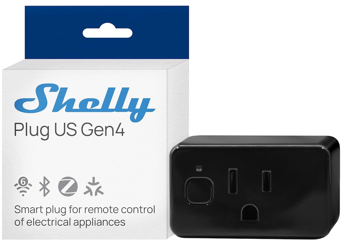
How does it work: WiFi power sockets like the Shelly Plug US support a well-documented HTTP API, which allows you to send commands over WiFi to switch the socket on or off. Crucially, they allow for local IP-based control without relying on a cloud server—a perfect solution for privacy-focused users.
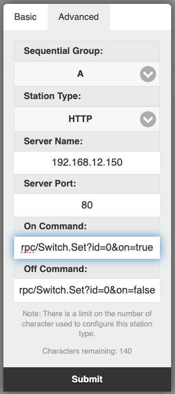
OpenSprinkler features a station type called “HTTP Station“, which sends user-defined HTTP commands when a zone opens or closes. By leveraging the smart plug’s API, zone actions transfer directly to the power plug.
Shelly US Plug Gen 4HTTP Station Config
How to set it up:
Configure your WiFi plug to connect to your router and obtain its IP address.
In OpenSprinkler, edit a zone and set its Station Type to HTTP.
Enter the plug’s IP address and Port in the Server Name and Port fields.
Configure the HTTP commands. Using the Shelly US plug as an example:
On command: rpc/Switch.Set?id=0&on=true
Off command: rpc/Switch.Set?id=0&on=false
Test the zone to verify the plug responds. (Note: If you use a different brand, check its API documentation for the correct command path).
Pros:
Galvanic Isolation: Complete air-gap isolation. No risk of messing with high-voltage wires.
Expandability: Easy to expand to multiple plugs / pumps. You aren’t limited by the physical ports on your OpenSprinkler unit.
Power Monitoring: Many plugs include power consumption monitoring.
Cons:
Not all WiFi plugs support HTTP API or local IP-based control.
Relies on your WiFi router (if WiFi is down, the pump won’t turn on).
Requires initial WiFi configuration on the plug.
2. Wireless but No WiFi: RFToy and RF Sockets
Best For: Long-range control where WiFi is weak.
Approx. Cost: ~$40 (RFToy + Sockets)
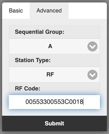
RF Power Sockets work on the 433MHz or 315MHz bands (unlike the 2.4GHz used by WiFi) and typically come with a dedicated remote. With an RFToy, you can decode the remote’s signal and replicate it using OpenSprinkler. OpenSprinkler’s ‘RF Station’ feature is designed exactly for this. You paste the code that RFToy intercepted from the remote, allowing the zone to toggle the socket.
RF power socket with remoteOpenSprinkler RF Station Config
Pros:
Range: RF signals often penetrate walls and floors far better than WiFi.
Isolation: Complete air-gap isolation. No wiring required.
Cost: RF sockets are cheaper per unit than WiFi plugs, making expansion more affordable.
Cons:
Requires purchasing an extra device (RFToy)
Usually one-way communication (no feedback signal to confirm the plug actually turned on).
3. The Safe Wired Way: IoT Relay
Best For: Users who want a reliable wired-only connection without messing with mains voltage.
Approx. Cost: ~$40
If you prefer the reliability of a wired connection but are uncomfortable stripping 110V wires, the IoT Relay is great. It looks like a power strip but features a green low-voltage terminal block on the side.
How to set it up:
Run two wires from OpenSprinkler (COM and a Station Port) to the green connector on the IoT Relay. It works with both AC-powered and DC-powered OpenSprinkler units.
Plug your pump into the “Normally OFF” outlet.
When the station activates, the outlet turns on.
Pros:
Zero Software Configuration: No WiFi configuration to manage.
Plug-and-Play: UL-listed and fully enclosed. Safe to use.
Reliable: It’s a hardwired connection, so it works even if your WiFi goes down.
Cons:
Current limit: Limited to ~12 Amps, which may not meet your pump’s specs.
Availability may be limited as there is only one manufacturer.
Expanding Cost is High if you need to switch multiple pumps.
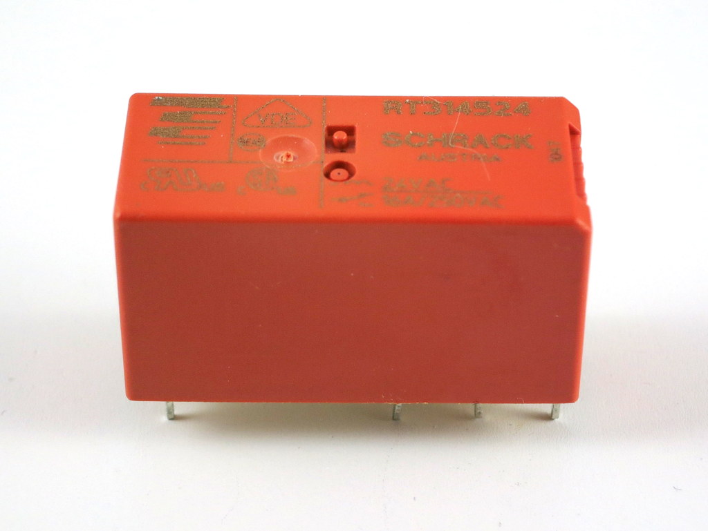
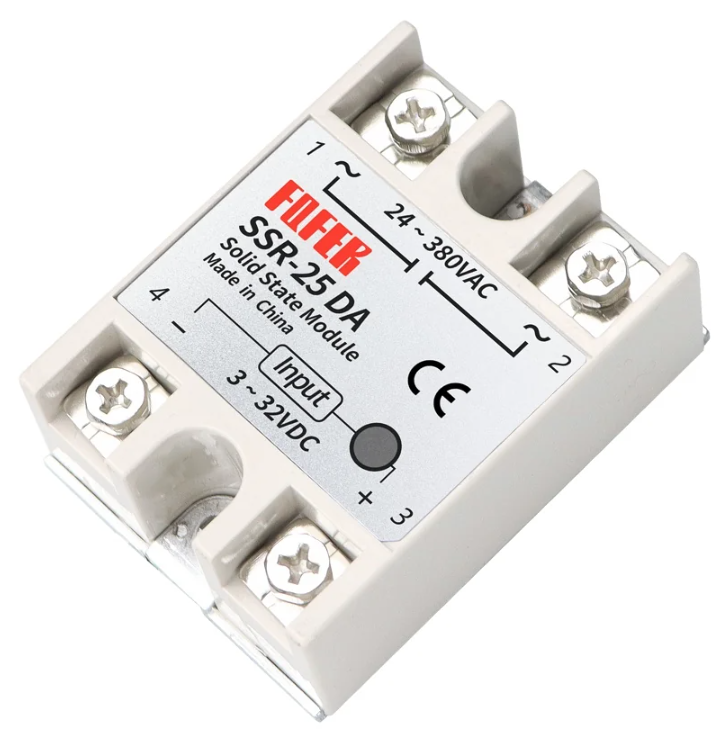
4. The DIY Way: 24VAC Relay / Solid State Relay (SSR)
This is the classic “old school” approach. You buy a standard relay with a 24VAC Coil (for AC-powered OpenSprinkler only; or, if using a DC-powered OpenSprinkler, get a DC Solid State Relay). You wire the coil to the OpenSprinkler just like a sprinkler valve, and wire your pump through the relay’s switch contacts.
Pros:
Lowest Cost: The cheapest option by far.
Reliable: Hardwired connection works even if WiFi fails.
Cons:
Safety Hazard: Requires proper enclosure and handling of exposed mains voltage.
Wiring Required: You need to handle both low and high voltage wiring.
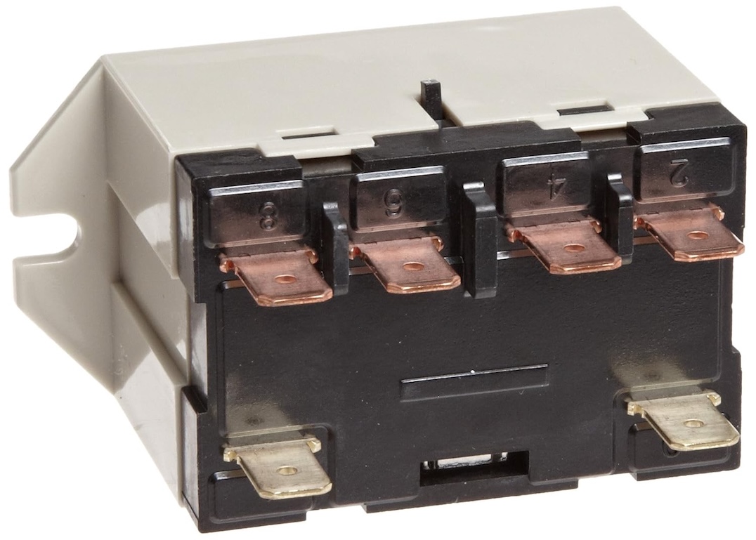
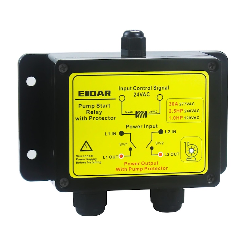
5. The Heavy Duty Option: Pump Start Relay
Best For: Large (1HP+), high power (>1500W), or 3-phase pumps
Approx. Cost: ~$50–$80
If you are running a massive well pump or a booster pump for a large lawn, small relays will weld shut due to the “inductive kickback” of the motor. You need a dedicated Pump Start Relay (from brands like Orbit, Hunter, or Rain Bird). These are essentially industrial-grade versions of Option 4, housed in a NEMA-rated outdoor box.
Pros:
Robust: Built to handle the massive in-rush current of large pumps.
Code Compliant: Safe for permanent outdoor installation.
If you have recently shopped for a new Chamberlain or LiftMaster garage door opener, you might have noticed a new term: Security+ 3.0. While “new and improved” usually sounds good, this latest update has thrown a wrench into the smart home community. Here is a breakdown of what is going on, why your existing gadgets might not work, and how we can help you get OpenGarage running on these new units.
What is Security+ 3.0?
Released in November 2025, Security+ 3.0 is the latest encryption protocol from Chamberlain Group (which owns Chamberlain, LiftMaster, and Craftsman).
How to spot it: These openers feature a White Learn Button (previous generations used Yellow, Purple, or Red/Orange). Some example models are: Chamberlain D1000, LiftMaster 2220L.
The Big Change: Unlike previous versions that communicated via wired data lines, Security+ 3.0 moves accessory communication to encrypted Bluetooth Low Energy (BLE). The wall button wires now provide only power, with no data signal to tap into.
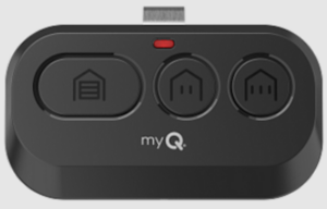
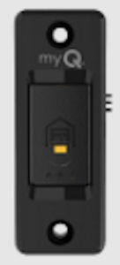
The remote and wall button that come with these systems look like the images below.
The Problem: The “Closed” Ecosystem
Because the new protocol relies on encrypted wireless communication, no third-party gadgets currently support it natively. RatGDO, Konnected, Tailwind, you name it, none supports it.
Devices that worked on Security+ 2.0 (like RATGDO) generally cannot control these new units directly.
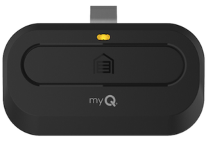
Chamberlain has aggressively moved toward a closed “myQ” ecosystem, locking out local control integration in favor of their cloud subscription model.
The Bottom Line: It is unlikely that native third-party support will arrive anytime soon.
The Solution: The “Sacrifice Remote” Method
If you have a Security+ 3.0 opener and want to use OpenGarage (or any third-party/open-source controller), there is a reliable workaround. It is the same trick we used for Security+ 2.0 before our native support arrived: Switching the button on a dedicated remote.
Instead of wiring OpenGarage to the motor unit directly, you wire it to a spare remote or door button that is paired to your door.
The Concept: You solder two wires to the button contacts inside a spare remote. We have a guide on how to do so.
The Connection: Connect those wires to the OpenGarage relay terminals.
The Result: When OpenGarage “clicks,” it electrically simulates a button press on the remote. The remote then sends the encrypted Security+ 3.0 signal wirelessly to open the door.
This bypasses the new encryption entirely by using Chamberlain’s own hardware to do the talking.
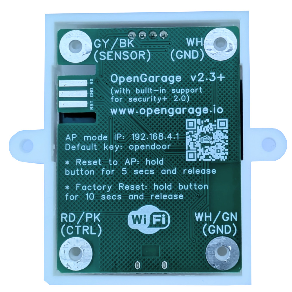
Configuration: When using this approach, you can either use the OpenGarage Classic Version (v2.2), or the newer v2.3+ with its ‘Security+ Version’ option set to ‘None’.
Limitations. The ‘sacrifice remote’ approach is a one-way communication. OpenGarage can send commands to trigger door actions, but it will not receive feedback or status updates from the remote.
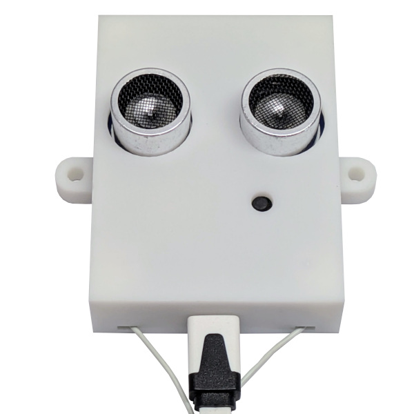
OpenGarage’s built-in ultrasonic distance sensor will still detect and report door status (open, closed, or in-between), so you’ll still have door position monitoring.
However, you will lose the ability to sense and control the garage light, as that requires two-way communication.
For most users, the ultrasonic sensor provides all the essential functionality needed for monitoring and controlling the door itself.
Free Soldering Service
We know soldering tiny wires onto a circuit board isn’t for everyone. We are happy to offer free soldering service for OpenGarage customers.
Here is how it works:
Send us your remote along with a prepaid return shipping label
We’ll solder the wires to the button contacts
We’ll send it back ready to connect to your OpenGarage
Save on Shipping: To avoid paying for return postage, you can mail your remote to us before placing your OpenGarage order. Simply include a note inside the box letting us know it is for an upcoming purchase; or send us a support ticket indicating you will be mailing us a remote and hold on to your existing order. We will then ship the soldered remote back to you in the same package as your order, so no return label is required.
This ‘hardware bridge’ is currently the most feasible way to keep using OpenGarage with the latest Security+ 3.0 GDOs.
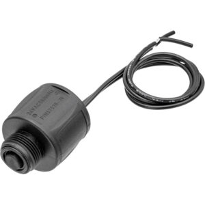
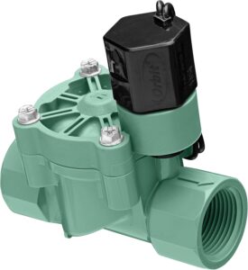
More than a decade ago, I published a blog post titled Understanding 24 VAC Sprinkler Valves. In that post, I took a close look at the sprinkler solenoid’s inrush vs. holding currents under 24 VAC, performed theoretical analysis and actual measurements, and explained the difference in the solenoid’s electrical behavior under AC vs. DC. While 24 VAC is a fairly old technology, it is still the standard for landscaping and irrigation projects today. These solenoid valves are cheap, robust, and widely available in home improvement stores.
24VAC SolenoidSprinkler Valve
In commercial sprinkler controllers, the most common way to switch these solenoids is by using triacs. Over the years, I’ve received many questions about triacs in sprinkler controller designs. So in this post, I’ll take an in-depth look at how to use a triac to switch sprinkler solenoids, interface it directly with a microcontroller (MCU) such as ESP8266, explain the two common power architectures used in real products, and discuss the choice of gate current-limiting resistors.
Triac Basics
You may already be familiar with transistors, but what is a triac? It is a 3-terminal semiconductor component, much like a BJT transistor or MOSFET, but primarily used to switch AC current rather than DC. With a standard NPN transistor, current flowing into the base-emitter junction “switches on” the transistor, allowing current to flow from the collector to the emitter. When the base current stops, the transistor switches off.
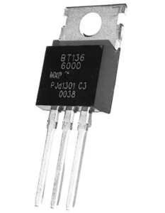
MAC97BT136Z0103MN
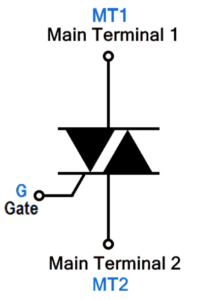
A triac’s three terminals are named Gate, Main Terminal 1 (MT1), and Main Terminal 2 (MT2). These are analogous to Base, Emitter, and Collector of a transistor. Similarly, current flowing between the Gate and MT1 can turn it on, allowing current to flow between MT2 and MT1. However, there are key differences:
Bidirectional Conduction: When on, current can flow between MT2 and MT1 in either direction. This makes the Triac suitable for switching AC load. In contrast, BJTs transistors conduct current in one direction only.
Bidirectional Gate Triggering: Unlike a transistor, a triac can be triggered not only by current flowing into the Gate, but also by current flowing out of the Gate. In other words, the gate current itself can be bidirectional. This leads to different operating Quadrants depending on signal polarity (see below).
Latching Behavior: When the Gate current is removed, a triac remains ON as long as the current flowing between MT2 and MT1 exceeds a minimum threshold called the holding current. When used with AC, the triac naturally turns off near each zero crossing when the load current falls below this threshold. This also explains why if you try to use a triac to switch DC current, it will only turn on but won’t be able to turn off unless you unplug the power.
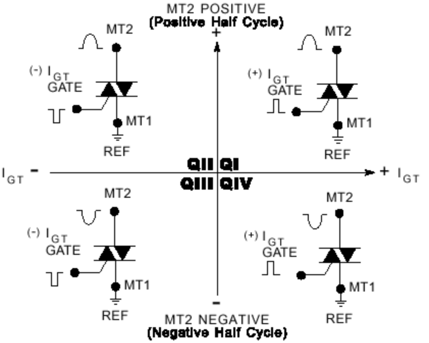
The Four Quadrants
Because a triac controls AC power that swings positive and negative, and the Gate can be triggered by either positive or negative current, there are four distinct operating modes, or Quadrants. These are defined by the polarity of MT2 and the Gate, both measured relative to MT1.
Why does this matter? While a triac is a bidirectional switch, it is not perfectly symmetrical on the inside. The silicon structure behaves differently in each quadrant, which means the Gate Trigger Current IGT (the current required to turn the triac on) varies by quadrant:
Q1, Q2, and Q3 are the most sensitive: IGTis the lowest in these quadrants.
Q4 is the least sensitive, often requiring 2-3x more trigger current than Q1.
Some Example Triacs:
MAC97 is a very low-cost, “sensitive-gate” triac commonly used in sprinkler controller circuits. Its IGT in Q1-Q3 is 3-5mA; and in Q4 is 7-10mA (some datasheets omit Q4).
BT136 is a higher-power triac. Its IGT in Q1-Q3 is 10mA max, and in Q4 is 25mA.
This matters greatly when driving a triac directly from a MCU’s GPIO pin. Some GPIOs may not source enough current to reliably trigger Q4. Some “High Commutation” (Snubberless) triacs do not operate in Q4 at all. This specific limitation drives the design decisions for the power architecture, as we will see next.
Circuit Design Assumptions
Before moving on, let me state a few assumptions to guide the design choices:
Single Power Supply: The same 24 VAC transformer powers both the solenoid valves and the logic circuits. This assumption is fairly obvious as it’s too cumbersome to require two separate power supplies.
Direct Triac Control from GPIO: As a sprinkler controller can have many zones, to minimize cost, we drive a triac directly by a MCU pin. Alternatives exist—relays, solid-state relays, opto-isolated drivers—but they are bulky, more expensive, some involving moving parts, and unnecessary in a single-supply design where true galvanic isolation does not exist anyway.
Half-Wave Rectification: We use a single diode to convert 24 VAC to DC for the logic. This choice is not primarily about cost—it is essential to make a single-supply triac design work. Specifically, half-wave rectification allows the MCU ground and one side of the AC waveform to share a common reference. Full-wave rectifiers, in contrast, create a “virtual ground” that would short-circuit the triac drive path in this topology.
Continuous Gate Drive: We will hold the gate signal active for the entire duration of the “ON” state, rather than pulsing it at zero-crossings like in classic triac circuits. This simplifies the circuit design. While it slightly increases power consumption, the added dissipation is negligible compared to the solenoid current.
Power Architecture for 24 VAC Sprinkler Controllers
Deriving DC from 24 VAC
The first step is converting 24 VAC into low-voltage DC (5V or 3.3V) to power the MCU and peripherals. This is done using a half-wave rectifier (single diode) and a bulk capacitor, followed by a step-down voltage regulator.
Linear Regulator. In older, non-smart controllers, the step-down regulator is often linear (e.g., a discrete zener-based regulator or a 78xx/79xx chip). This is feasible only if the MCU’s current draw is small. You see, a 24 VAC transformer, under light load, can output an unregulated voltage as high as 30 VAC RMS. This corresponds to a peak voltage of 30*1.414 = 42.4V, which is dangerously high. In fact, if you touch the two wires of the transformer, your fingers may get a tingling sensation!
For a small MCU drawing 10mA, dropping 42.4V to 3.3V dissipates about (42.4V-3.3V)*0.01A = 0.391 W. Not too bad with a decent heat sink. This is why linear regulators are common in legacy controllers.
Switching Regulator. Modern, smart controllers typically have a WiFi or Ethernet chip that can easily draw at least 100mA. This would push the power dissipation to nearly 4W – impractical for a linear regulator. For this reason, modern smart controllers all use switching regulators (e.g., LM2574 or LM2596-class chips) to efficiently step down high voltage without excessive heat. The old-school MC34063 can also be used, though its low switching frequency may cause audible noise under light load.
To directly interfacing a MCU with the triac, there are two topology choices.
Design Choice A: MT1 Tied to the Positive Rail
If you reverse-engineer a legacy non-smart controller (e.g., Orbit 28964), you will typically find:
A negative voltage regulator (e.g., via a zener-based circuit or a 7905 chip).
The triac’s MT1 is tied to the positive rail (MCU’s VCC).
Active LOW Logic: The MCU pulls the gate LOW to turn it on. This is similar to how a PNP transistor works as a high-side switch.
Why did they do this? By tying MT1 to MCU’s VCC, the Gate is always pulled negative to MT1 when active. This forces the triac to operate in Q2 and Q3, both high-sensitivity quadrants. The MCU only needs to sink (and never source) current, which is ideal for older MCUs with weak GPIO capability, including open-drain-only outputs. In addition, GPIOs default to high or Hi-Z at power-on, keeping valves safely off. Finally, as the MCU consumes very little current, a linear regulator is acceptable.
The Downside: Setting VCC as voltage reference results in a negative GND voltage, which can be unintuitive and confusing. Extending the system with sensors and additional hardware (which often assume standard GND) is harder.
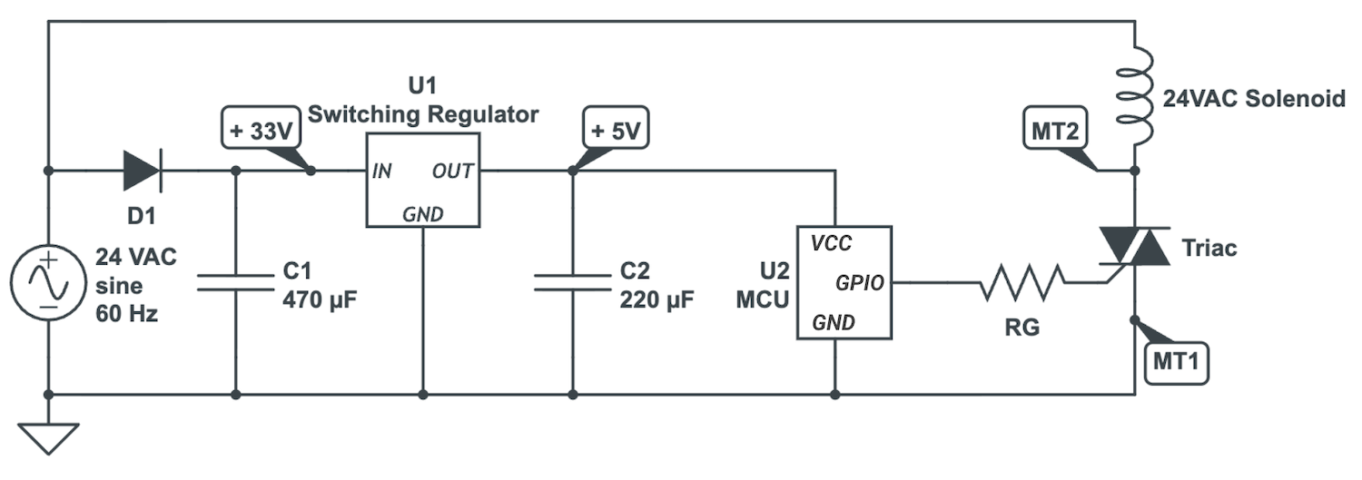
Design Choice B: MT1 Tied to GND
Modern smart controllers typically use a standard “Common Ground” topology:
The triac’s MT1 is tied to MCU’s GND, much like the NPN transistor’s emitter is tied to GND.
Active HIGH Logic: MCU pulls the Gate High to turn it on.
The power circuitry uses a standard positive voltage switching regulator.
Why do they do this? Positive voltage switching regulators are more common and cheaper to source than the negative voltage counterparts, especially when a high input voltage rating (>50V) is required. Also, using GND as voltage reference is easier to understand, debug, and extend.
The Downside: With MT1 grounded, the triac operates in Q1 and Q4. While Q1 is easy to drive, Q4 is the least sensitive quadrant. This is why modern designs almost universally use sensitive-gate triacs such as MAC97 (THT) or Z0103MN (SMD), with Q4 IGT ≤ 7 mA.
When higher-power-rating triacs are needed, you have to watch out for the Q4: if the GPIO cannot provide sufficient IGT in Q4 (in fact, some snubberless triacs don’t support Q4 operation at all), the triac would simply not conduct in half of the AC cycles, resulting in unreliable valve activation and audible noise.
Gate Resistor Selection
To drive a triac directly from a MCU, a gate resistor is required to limit current. The resistor must be small enough to guarantee sufficient IGT in Q4, but large enough to avoid unnecessary power waste or exceeding the MCU GPIO’s current limit.
Assume VCC = 3.3 V, triac’s Q4 IGT = 7 mA (max), Gate forward voltage = 1.5 V (worst-case), we have: RG = (3.3 V – 1.5 V) / 7 mA = 257 Ω. In practice, values in the 220-330 Ω range should work well.
Using Shift Registers or IO Expanders: When controlling many zones, GPIOs can quickly run out. In this case, adding a shift register (e.g., 74HC595) or I2C I/O expanders (e.g., PCA9535) is a common solution. But be careful: these devices may have much weaker current sourcing capabilitythan GPIOs. Voltage drop under load must be considered, and gate resistors may need to be reduced accordingly. If the required IGT cannot be met, an external transistor gate driver may be necessary.
One additional note: if the I/O expander outputs are pulled high at power-on, it will be necessary to add a strong gate pull-down resistor (e.g., 10 kΩ) to keep the gate LOW at power-on. Otherwise, you will notice the sprinkler solenoids momentarily pop up at power-on, which is undesirable.
Verify Gate Current Using an Oscilloscope
The calculation of gate current above assumes a static measurement, but since the triac is controlling an AC load, the forward-on voltage and gate current are both dynamic. Therefore I decided to take measurements using an oscilloscope to make sure the triac is reliably switched on.
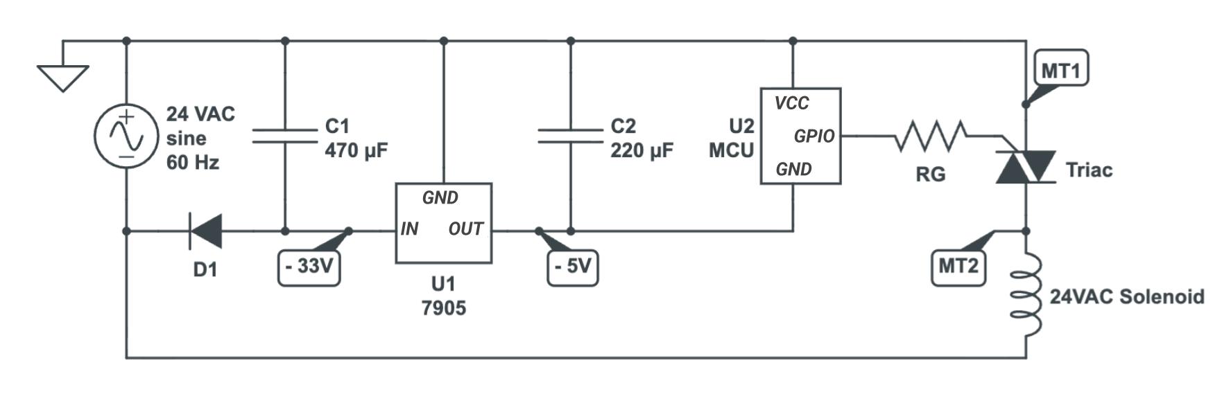
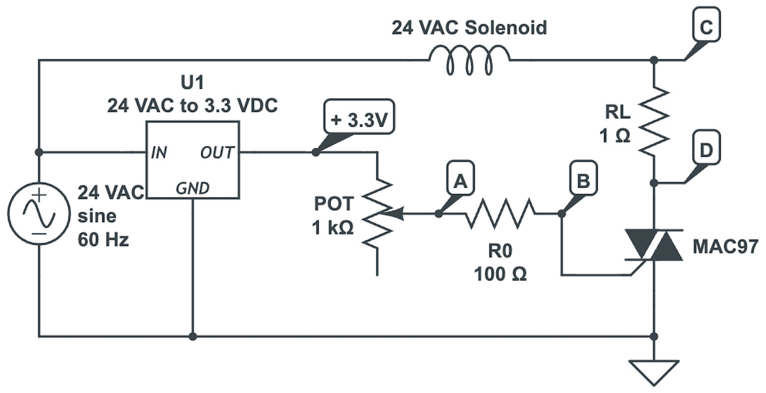
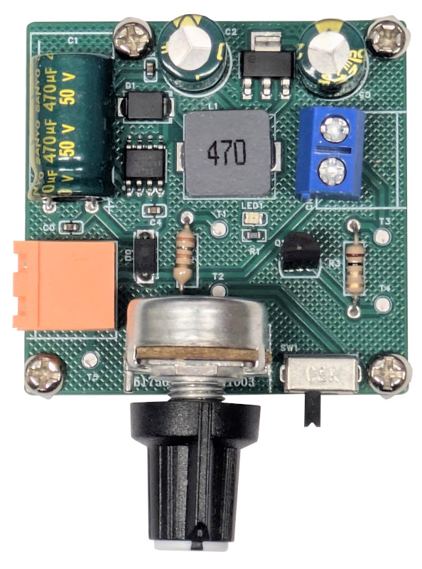
To do so, I made a simple prototype circuit consisting of a 24 VAC to 3.3 VDC switching regulator, a MAC97 Triac, an adjustable gate resistor (100~1100 Ω), a 1 Ω shunt resistor for measuring load current, and a terminal block to hook up a 24 VAC solenoid. Below is a simplified schematic and the actual photo of it.
I hooked up a 4-channel oscilloscope to test points A, B, C, D respectively: A and B are the Gate voltages before and after the fixed 100 Ω resistor; C and D are Load voltages before and after shunt resistor RL. Therefore (VA-VB) / 100 is the gate current, and (VC-VD) / 1 is the load current.
By varying the potentiometer from low to high, I found the point at which the load current starts to miss half of the AC cycles, indicating the triac was still firing in Q1 but failing in Q4. Below are the measurement screenshots. Channels A, B, C, D are displayed in Yellow, Cyan, Purple, and Blue respectively.
When RG = 270 Ω:
All channels (RG = 270 Ω)
Channels A, B, and (A-B) displayed in violet
We can see that (A-B) varies between (1.8-0.88) = 0.92 V and (0.8-(-0.64))=1.44 V, corresponding to 9.2~14.4 mA gate current. This is well above the required trigger current, therefore the triac is fully on.
The “Negative Voltage” Anomaly. You might notice in the screenshots that the Gate voltage VB is negative in some regions, even though the MCU is continuously holding the gate signal High (thus current is flowing into the Gate). At first glance, I was greatly puzzled by this, as it seems to suggest a region of “negative resistance”.
This effect is not caused by the inductive nature of the load—repeating the experiment with a purely resistive load still shows the same negative VB behavior. This suggests that the phenomenon is possibly related to the triac’s internal behavior in Q4. Since MT1 serves as the “Ground” reference, when a large current surge flows out of MT1, it can momentarily make the Gate appear negative relative to MT1 (even though current continues to flow into the Gate). Interestingly, as this negative VB happens to occur in Q4 (when current flows from MT1 to MT2), it effectively increases the voltage potential VAB across the Gate resistor, thus it actually helps keep the triac triggered in Q4.
The screenshot below show the direct measurement of VCD. The peak voltage is 0.37 V, corresponding to 260 mA RMS current. This is consistent with the typical holding current of a 24 VAC solenoid.
Direct measurement of VCD (RG = 270 Ω)
When RG = 390 Ω:
All channels (RG = 390 Ω)
With a larger gate resistor, (A-B) now varies between (1.52-0.84) = 0.68 V and (0.2-(-0.92))=1.12 V, corresponding to a gate current of 6.8~11.2 mA. The triac is still solidly on.
When RG = 920 Ω:
All channels (RG = 920 Ω)
This is where things start to collapse. The gate current drops to only about 2.6~2.7 mA. While the triac is still triggering in Q1, it fails in Q4. Consequently, the load current starts to miss half of the AC cycles, clearly visible in the VCD waveform below. The solenoid also begins to make a loud buzzing noise.
Direct measurement of VCD (RG = 920 Ω)
Additional Considerations
There are some additional considerations I omitted above. These are less of a concern for sprinkler controllers, as they run on low voltage (24VAC), but can be important when using triacs to switch general AC loads that are high-voltage and/or high-current.
1. Latching vs. Holding Current Triac’s datasheets distinguish between Latching Current (minimum MT2-MT1 current required to turn the triac on) and Holding Current (required to stay on). With inductive loads like solenoids, current lags voltage. If you were using short pulses to trigger the triac, the pulse might end before the current rises high enough to latch, causing the triac to fail. In our design, however, this distinction is largely irrelevant because the Gate is held active continuously. The triac is retriggered every half-cycle, so precise latching timing is not critical.
2. Critical dV/dt and False Triggering “dV/dt” refers to how fast the voltage across the triac changes. If voltage spikes too fast, the triac can trick itself into turning on without a Gate signal. This can be a major concern when switching a high-voltage load, such as 110 V or 220 V. In our case, however, 24 VAC is a relatively low voltage, thus the risk of false triggering is low.
3. Snubbers and MOVs / TVS Diodes Sprinkler wires run underground and outdoors, making them giant antennas for lightning and static induction.
MOVs or TVS Diodes: It is recommended to place an MOV or TVS diode across the 24 VAC input terminals. This acts as a surge protector, clamping high-voltage spikes before they blow up your triac or even MCU.
Snubber: RC snubbers are optional but can further reduce stress on the triac.
Summary
Triacs are a great choice for switching 24 VAC sprinkler solenoids: they are cheap, compact, and have no moving parts for long-term reliability. With careful attention to quadrant operation, gate current, and power architecture, a triac can be driven directly from a microcontroller without opto-isolation or external drivers.
Design Checklist
Use a sensitive-gate triac with low Q4 trigger current requirement
The MT1-to-GND design is generally preferred for WiFi-enabled designs due to switching regulator availability.
Choose gate resistors based on worst-case Q4 IGT, and account for under-load voltage drop if using shift registers or I/O expanders.
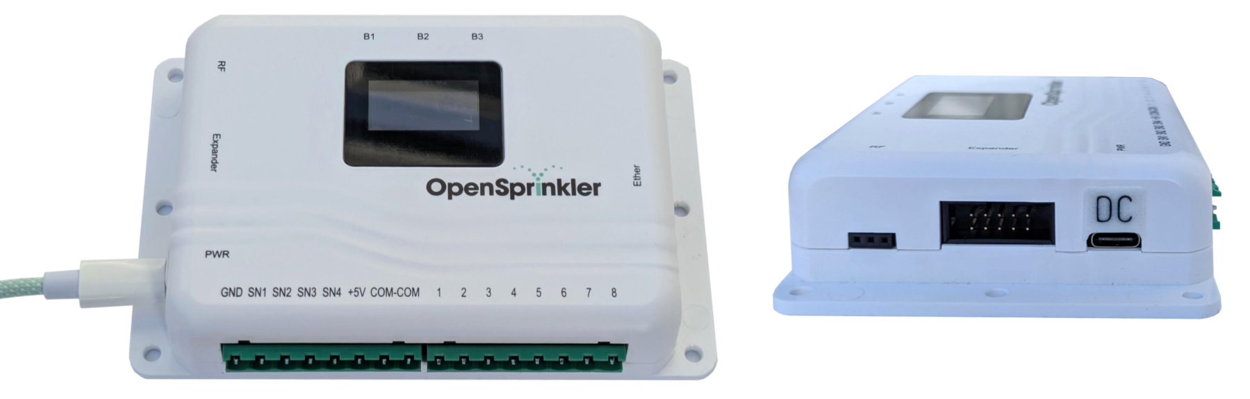
Back in July, we debuted the AC-powered OpenSprinkler v3.4, featuring a new, redesigned enclosure and several hardware improvements (read here). Building on that, today I’m thrilled to unveil the upcoming DC-powered OpenSprinkler v3.4 — the very first OpenSprinkler powered by USB-C! Check out some sneak-peek photos below:
This model shares the same sleek, low-profile enclosure as its AC counterpart. This means it features a single-layer circuit board, two extra sensor ports (SN3, SN4), and an external Ethernet connector for easy installation of the wired Ethernet module.
The key innovation, however, is the move to USB-C as the power source. This change offers several powerful advantages, rooted in our goal of modernizing the sprinkler control circuit.
Why Move Away from 24 VAC?
Traditionally, most sprinkler controllers rely on 24VAC to operate sprinkler valves. This is a dated standard with several notable drawbacks: 24VAC power adapters are heavy, bulky, expensive, and difficult to source outside North America. For international users, finding a compatible 24VAC adapter for their country is a major pain point. Furthermore, their output voltage is unregulated and they lack current limiting circuitry, posing a major risk in the event of a short circuit.
The Origin of DC-Powered OpenSprinkler
When I designed the first DC-powered OpenSprinkler, my goal was to eliminate the dependence on 24VAC and switch to DC power adapters, which are lightweight, compact, inexpensive, and globally available. DC power supplies also include built-in current limiting and protection circuitry — making them safer to use and resilient to faults.
However, to work with standard 24VAC sprinkler solenoids, a DC controller must simulate the behavior of a 24VAC solenoid using DC-only voltage. Specifically, under AC power, a solenoid coil naturally limits its current through inductive reactance: 1. Inrush Current: When the solenoid first activates, it draws a high inrush current (500–700mA) to energize the plunger. 2. Holding current: Once energized, the solenoid requires a lower, stable holding current (200–300mA) to remain open. Under AC power, this reduction happens automatically because the the plunger (now moved in) increases the coil’s inductance, which in turn raises it reactance and limits the current.
To replicate this effect under DC, OpenSprinkler uses a 7.5VDC adapter as its main power source. Since a typical sprinkler solenoid has a coil resistance of 30–40Ω, this voltage naturally produces the 200–300mA holding current required to keep the valve open. To generate the initial inrush current, however, it uses an internal voltage booster to momentarily raise the voltage to 21VDC. This dual-voltage method is essential, because the high inrush current is necessary to reliably open the valve, but if applied continuously, it can overheat the solenoid coil and significantly reduce its lifespan.
Why USB-C is a Game Changer
The DC-powered circuitry is a proven innovation that has allowed users to ditch the outdated 24VAC technology for years. The new v3.4 now takes this a step further by adopting USB-C as its main power source. This introduces three key benefits.
1. Universal Availability
USB-C is a global standard for everything from phones to laptops. This makes sourcing the power adapter incredibly easy, no matter where you are. These adapters are powerful yet lightweight, affordable, and feature built-in protection circuitry.
2. Adjustable Voltage (USB-C PD & PPS)
Modern USB-C adapters are essentially smart, adjustable power supplies. Those that support the PPS (Programmable Power Supply) standard can provide a continuous voltage range (e.g., any voltage between 5.0V and 15.0V). This is a game-changer for optimizing sprinkler valve performance.
Different solenoids have different coil resistances and ideal holding currents. By matching the holding current to the manufacturer’s spec, you prevent overheating (from too much current) and unreliable operation (from too little). With v3.4, you can now calculate and set the ideal input voltage for your specific valves, and the controller will negotiate with the USB-C adapter to provide it. This level of customization ensures best efficiency and reliability. For example:
A 30Ω coil (older Orbit valves) with 250mA holding current works best at 7.5VDC
A 60Ω coil (newer Orbit valves) with 200mA holding current works best at 12VDC
In previous DC models, you would have to swap the power adapter to match the voltage. With USB-C, the controller automatically negotiates the optimal voltage from a single USB-C power source.
3. Mistake-Proof Design
Previous DC models used a standard barrel jack. Despite our best effort to prevent mistakes, some users would accidentally plug in a 24VAC adapter (simply because the plug fits in), resulting in damage. USB-C completely eliminates that risk: an AC adapter plug physically cannot fit into a USB-C port.
Q: How does the controller customize the input voltage? A: It has a built-in USB-C Power Delivery (PD) chip that negotiates the requested voltage directly with the USB-C adapter.
Q: How can I determine the ideal voltage to set for my valves? A: Multiply your valve’s holding current by its coil resistance. Example: 250mA × 35Ω = 8.75VDC. The holding current is typically specified in the valve’s datasheet. The coil resistance is also in the datasheet, or otherwise can be measured using a multimeter.
Q: Can I use any USB-C charger? What if mine doesn’t support PPS? A: If the adapter supports PPS, the voltage can be set precisely. If your adapter only supports fixed voltages (5 V, 9 V, 15 V, etc.), it will select the nearest match.
Q: Does v3.4 still include an internal voltage booster? A: Yes. The controller still needs to reliably generate an impulse voltage (21VDC) for the inrush current, which not all USB-C adapters can provide. The internal booster remains, ensuring consistent performance regardless of your charger’s capabilities.
Q: How much current can it support? A: This is determined by your USB-C adapter’s power rating. A standard 18W adapter can provide roughly 2A at 9V, while more powerful (30W) adapters can supply even more current.
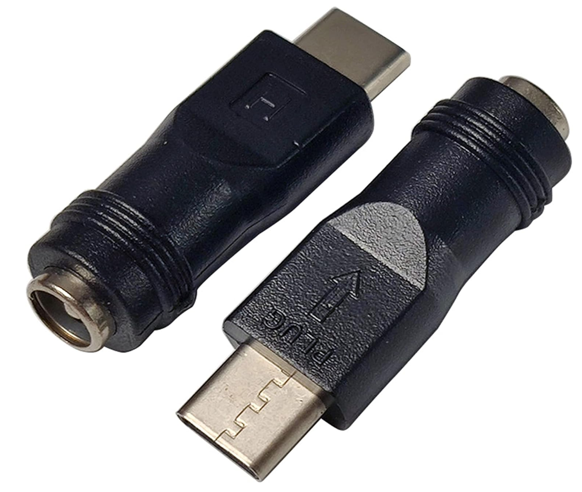
Q: Can I still use my 7.5VDC adapter with a barrel plug? A: Yes, you can use a simple dc-female-to-USBC adapter like the one shown below. It’s a simple pass-through converter and does NOT do any voltage conversion. However, note that the input voltage will be fixed at your adapter’s rating (e.g., 7.5V) and will not be adjustable.
Q: How can I power v3.4 using a 12VDC solar setup? A: If your solar power source has a standard barrel plug, you can use the same dc-female-to-USBC adapter shown above.
Q: Which expander is it compatible with? A: Fully compatible with DC Expander v3, just like previous v3 models.
Q: Will DC v3.3 still be available? A: Yes, we will continue selling the v3.3 model while supplies last. In the meantime, we will keep offering the v3.3 circuit board without an enclosure for repairs and DIY projects.
Q: Can I reuse my existing wired Ethernet module? A: Yes — it uses the same W5500 Ethernet module as v3.3.
Q: I recently bought an OpenSprinkler DC v3.3. Can I exchange it? A: Yes, if your purchase was made within the last 30 days, it qualifies for an exchange under our no-questions-asked return policy. Please see our terms and conditions for details.
Exciting news! We’re preparing to release a new hardware revision of OpenGarage: version 2.3+. This will be the first OpenGarage to include native support for Security+ 2.0, eliminating the need for an external Security+ adapter. The hardware form factor is identical to OpenGarage v2.2, but with enhanced circuitry and software library courtesy of the open-source work of Ratgdo.
With this upgrade, OpenGarage can communicate directly with Security+ 2.0 garage door systems, enabling new capabilities such as reporting partially open status and controlling the opener’s light. Here’s a sneak-peek photo of version 2.3+:
FAQ
Q: What is Security+ 2.0? A: Security+ 2.0 is a garage door opener technology introduced by Chamberlain around 2011 and sold under the LiftMaster, Chamberlain, and Craftsman brands. It uses rolling-code encryption for both remotes and wall button controls, providing stronger security and more reliable signals.
You can usually identify a Security+ 2.0 opener by its yellow “learn” button (and often a yellow antenna too). If you’ve purchased a garage door opener of the above brands in the last several years, there’s a good chance it uses Security+ 2.0. If you are not sure, take a look at your opener’s user manual, usually it will explicitly mention the term Security+ 2.0.
Unlike older systems, which worked by simply shorting the two button wires, Security+ 2.0 enforces the use of encoded signals. This allows not only open/close commands, but also richer feedback such as whether the door is partially open or the light is on.
Q: Why couldn’t earlier versions of OpenGarage support it directly? A: Previous versions (like v2.2) relied on shorting the two button wires — which no longer works with Security+ 2.0. To control those systems, you had to use an external adapter (e.g., the Security+ 2.0 adapter that we sell) as a “middleman.” When the two wires on the adapter are shorted, it generates encoded signals accepted by the opener.
Q: What is Ratgdo? A:Ratgdo (Rage Against The Garage Door Opener) is an open-source project developed by Paul Wieland. It allows a microcontroller (such as an ESP8266) to directly speak the Security+ 2.0/1.0 protocols via GPIO pins. In effect, Ratgdo replicates what a proprietary Security+ 2.0 adapter does — enabling direct open/close/stop commands, door status reporting, and even light control.
Q: What hardware changes are in OpenGarage v2.3+? A: v2.3+ incorporates the same type of control circuits shared by the ratgdo community (see rat-ratgdo). It uses two MOSFETs — one for transmitting, one for receiving — to safely interface with the opener’s signal/button wire (typically 12 V DC).
⚠️ Important: Because of this design, v2.3+ is NOT compatible with legacy openers that use AC (e.g., 24 VAC) on the control /button wires. Using it on those systems could damage the circuitry. For those setups, OpenGarage v2.2 remains the recommended model.
Q: When will OpenGarage v2.3+ be available? A: We’re now accepting pre-orders, with shipments expected no later than early October 2025.
Q: Does v2.3+ still use the built-in ultrasonic distance sensor? A: Since Security+ 2.0 directly reports the door’s open/close status, there’s no need to rely on the ultrasonic sensor for that purpose. In Security+ 2.0 mode, v2.3+ will not use the sensor for door status, but it will continue using it to detect vehicle presence in the garage.
Q: Will OpenGarage v2.2 still be sold? A: Yes. Since v2.2 is compatible with legacy openers, including both AC and DC systems (via its onboard solid-state relay), we’ll continue offering it alongside v2.3+.
Q: If v2.2 works with an external Security+ 2.0 adapter, why upgrade to v2.3+? A: Two key reasons:
More features — v2.3+ enables additional features such as reporting partial open status and toggle the opener’s light, which Security+ 2.0 adapters can’t provide.
Lower cost — buying v2.2 plus an external adapter costs more than a single v2.3+.
Bottom line: Choose v2.3+ if your garage door system is made by Chamberlain, LiftMaster, or Craftsman. For all other brands, use v2.2. (Technically, any system with button wires that output DC below 20 V can use v2.3+, but it offers no benefit on other brands since they don’t support the Security+ protocol.)
Q: Can I modify my existing v2.2 to support Security+ 2.0? A: In theory, yes — by adding MOSFETs and resistors. But unless you’re experienced with soldering, we don’t recommend it.
Q: What about Security+ 1.0? A: Security+ 1.0 (mid-1990s–2010) was Chamberlain/LiftMaster’s first rolling-code system. It used colored learn buttons (purple, red, orange, green), but shorting the two wires still worked. Its status reporting is limited compared to 2.0. Ratgdo also supports Security+ 1.0, so with v2.3+ you can still read door status and control the opener’s light on those systems.
Q: I just bought an OpenGarage — can I exchange it for v2.3+? A: Yes. Purchases made within the last 30 days qualify for our no-questions-asked return/refund policy (see our terms and conditions).
Summary
✨ With v2.3+, OpenGarage now natively supports the Security+ 2.0 technology — no additional adapters required, more features unlocked, and the same compact design!