Feed on
Posts
Comments


Update: OpenSprinkler new mobile app (native version) is now available on all platforms. Search ‘opensprinkler’ in iOS App Store, Android Play Store, or Windows Phone Store, then download and install the app. Additional details can be found in this blog post.


In this blog post, I will walk you through the basic steps to set up and use the OpenSprinkler mobile web app developed by Samer Albahra. I’d like to thank Samer for making this app available, and credits should be attributed to him. Initially I was planning to write a long post with textual instructions. But then I felt this app is such a significant contribution that it deserves its own video tutorial. So please take a look at the video below first. As the video is already quite long, I will keep the textual information short, with only a summary of the necessary steps, download links, and pointers to resources. Since the app is a work in progress, feel free to leave your comments and suggestions at the Rayshobby Forum.


Prerequisites

In order to use this app, you will need a working OpenSprinkler setup, such as

  • OpenSprinkler 1.x running firmware version 1.8.2 or above (note: firmware 1.8.3 preferred);
  • or OpenSprinkler 2.0 running firmware version 2.0.0 or above;
  • or OpenSprinkler Pi any version running Dan’s interval_program (equivalent to firmware 1.8.2).

If you have OpenSprinkler 1.x with firmware earlier than 1.8.2, please follow the Firmware Update Instructions to re-flash the microcontroller with the latest firmware.

Also, if you are not familiar with the concept of a mobile web app, please take a look at my previous post about the app. Simply speaking, it’s an app that runs in a browser. It’s somewhat slower than a native app, but the biggest advantage is that it’s cross-platform (i.e. same app runs on both iOS, Android, etc., even desktop browsers). By adding the web link to home screen, the app will appear like a true native app.

NOTE to keep in mind: the app provides an alternative front end to the OpenSprinkler controller. The default front end, which is the controller’s webpage (accessed by typing in the controller’s ip in a browser), is still available and functioning. Any operation you apply through the app will also be reflected in the default front end.


Version 1: Hosted App on Rayshobby.net

Samer made the app available in two versions. The first is a hosted app available at the following url:

http://rayshobby.net/apps/sprinklers/

Type this in the browser on your smartphone, tablets, or even desktop computer, and you can start using it immediately. However, before you proceed, make sure you have port forwarding set up on your router. See below.

Port Forwarding: because the hosted app needs to communicate with your OpenSprinkler through HTTP commands, your controller must be accessible by the rayshobby server. To do so, you need to set up port forwarding on your router, so that an external HTTP request to your router will be mapped to your OpenSprinkler controller. This requires knowing your OpenSprinkler’s IP address and port number (default is 80). Please refer to your router’s user manual for instructions. In addition, you can use dynamic DNS service (such as dyn.com, freeDNS etc.) to set up a DNS name for your router (i.e. an easy-to-remember name such as rayshobby.dyndns-web.com instead of the router’s IP). Most routers support dynamic DNS service as well.

Logging in: going back to the app, on the log-in page, type in your router’s IP (or dynamic DNS), optionally followed by the port number (if it’s not the default 80), and your OpenSprinkler’s access password (the default password is ‘opendoor’). Then click on the button.

Add Link to Homescreen: most mobile browsers support adding (or bookmarking) a link to homescreen. This creates a homescreen icon, which you can simply click to start the app each time.

Features: the app has implemented all features available on the latest OpenSprinkler firmware. It provides a more stylish and intuitive interface than the default front end. For example, you can use slidebars to set values, there is a status bar that shows the currently running station with count-down timer, the app’s program preview provides an easy way to switch to a different day, everything is optimized for mobile viewing experience, and finally since the app is a front end itself it does not require external Javascript as required by the default front end. Please follow the video tutorial above and try out the app yourself. Most of the features are self-explanatory.

Donation: Samer wrote the app and shared it for free. I can’t thank him enough for making this app available and so polished. If you like the app, please consider donating some money to support his work. The donation link is available on the app’s ‘About’ page (accessible by clicking the control panel button at the upper-left corner of the app).

Summary: to summarize, in order to use the hosted web app, all you need is to set up port forwarding on your router, and use the hosted web app’s url above. That’s it!


Version 2: Self-Installed App on A Local Web Server

The second version is a self-installed app that requires using a local web serer. Most of the features in the second version are shared with the hosted web app above, however, by using a local web server you gain two additional features that may be very useful: logging, and weather-based rain delay.

Installation: for installation, simply follow the instructions on my previous post about the web app, particularly the How to Set it Up (using Raspberry Pi as example) section.

Logging Feature: the self-installed app records stations runs and keeps the history of station runs in a log file. On the app’s homepage you will see a button. Clicking on it brings out the log view, which categorizes log data by station names.

Weather-based Rain Delay: having a local web server also allows weather-based rain delay. This feature is developed by Andrew Shilliday (thank you, Andrew!). Basically, it’s a script that periodically pulls data from Yahoo Weather API (using your location information), and enforces rain delay if certain weather conditions are met. Technically, the data from Yahoo Weather contains a condition code that tells the local weather condition (e.g. showers, thunderstorm etc.). The script is associated with a data file that defines the amount of rain delay hours when a certain condition code is detected. For installation and setup instructions, please refer to Andrew’s GitHub page:

https://github.com/andrewshilliday/OpenSprinkler-WebRainDelay

This is a work in progress, and we are planning to integrate this feature into the OpenSprinkler firmware so that in the future it will not need installation any more.


Resources and Links

I am really glad to see these wonderful user contributions. They tremendously help make OpenSprinkler a better product, and I learned a lot through the forum discussions, which in turn inspired new ideas. Below I list the currently active forum threads that are related to the mobile web app development and the weather feature:

We are actively working on making the weather-based control a firmware feature. If you have ideas and suggestions, please feel free to leave them at the forum. Thanks!


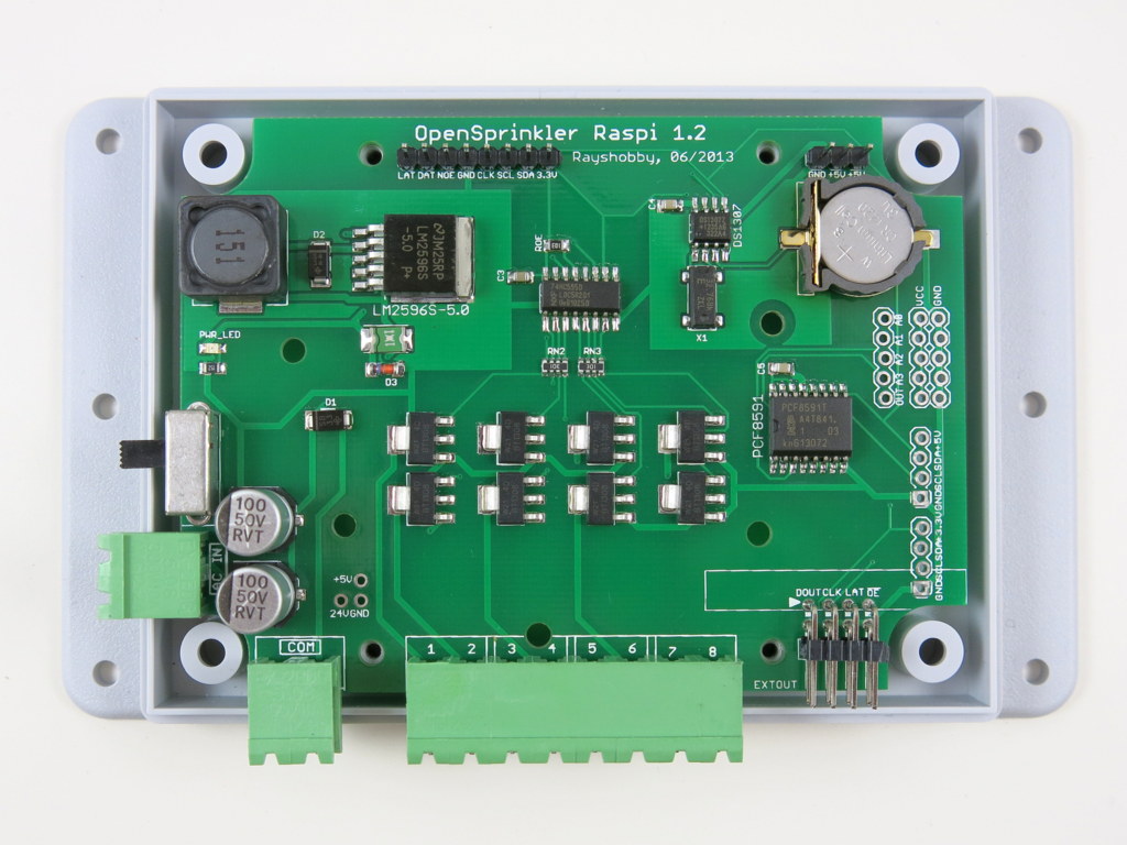
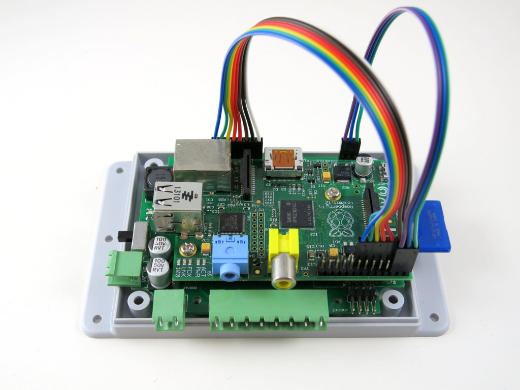
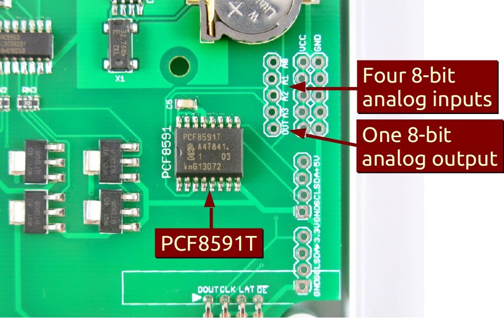
Hi, this is a new product post for OpenSprinkler Pi (OSPi) v1.2. Since its original release, OSPi has become a very popular product. This version is a minor revision. The main change compared to version 1.1 is the addition of a PCF8591T 8-bit A/D D/A converter, which provides four independent 8-bit analog input pins, and one 8-bit analog output pin. The reason this has been added is that Raspberry Pi (RPi)’s GPIO pins do not have built-in ADC capability. In order to interface with analog sensors (such as soil moisture sensor, light sensor etc.), you would need an ADC unit. The addition of the PCF8591T chip allows OSPi to provide on-board analog inputs as well as output. This makes it more convenient for your prototyping need. Other than this, the rest of the circuit is pretty much the same as before, with 24V AC to 5V DC switching regulator (based on LM2596S), DS1307 RTC and backup battery, 74HC595 shift register and triacs. Here are two pictures of the OSPi v1.2 board:

IMG_0004IMG_0008

If you Google ‘RPi ADC’ you will find plenty of choices of ADC modules and tutorials on how to get them to work with RPi. Why did I pick PCF8591T? There are several reasons. First, it’s low-cost: volume pricing is just a couple of dollars per piece. Second, it provides four independent A/D channels, and one D/A channel. This means you can use one chip to interface with 4 different analog sensors, and additionally you can get one channel of analog output. According to the datasheet, the analog output is implemented with resistor divider chain, which is sometimes a better choice than PWM. Also, it uses I2C interface, so it doesn’t require any extra GPIO pins from RPi. Overall it’s a very attractive choice. The main downside is that it’s only 8-bit. This means the analog input value is on a resolution of 0 to 255, same with analog output. A lot of the other chips provide at least 10 bits of precision. But I figured that 8-bit is sufficient in many cases, so I settled with this choice.

The chip, together with analog pinouts, are located on the right-hand side of the board:
IMG_0006_annotated

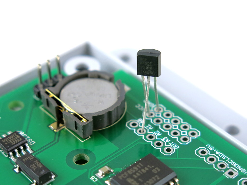
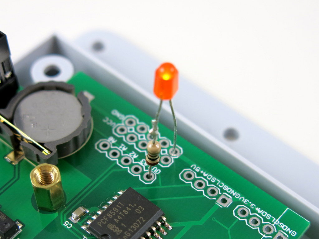
For convenience, I’ve also provided a separate pair of VCC and GND pinouts for each analog channel. The picture on the left below is an example of plugging in a MCP9700 temperature sensor directly to the pinouts; and the picture on the right below shows an LED (with current limiting resistor) plugged into the analog output channel, to allow programmable control of the LED brightness.

IMG_0005IMG_0009

Suppose this gets you interested, the next question is how to program RPi to talk to the ADC chip? Fortunately there are plenty of tutorials online. In particular, I found the following posts very useful:

If you are confused and just want a quick demo. Here is a short tutorial to get you started.

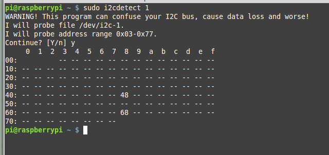
First, run sudo i2cdetect 1 to check if the PCF8591T chip is detected. (Note, if you own RPi rev. 1 you should run sudo i2cdetect 0 instead). You should then see a printout like the following. This shows it has detected two I2C devices, one is at address 0x68 (that’s the DS1307 RTC), and one 0x48 (this is PCF8591T).
pcf8591t_i2cdetect

Next, you can use the i2cget command to read analog values from a particular channel. For example, run
sudo i2cget -y 1 0x48
repeatedly to sample the analog value from channel 0 (pin A0). To change to channel 1 instead, run
sudo i2cset -y 1 0x48 0x01
and then if you run sudo i2cget -y 1 0x48 that will return sampled value of channel 1, and so on.

To enable analog output, use the i2cset command. For example:
sudo i2cset -y 1 0x48 0x40 0xff
where 0xff is the 8-bit analog output value. You can change it to any value between 0x00 to 0xff to enable 256 grades of values. Since the chip is powered by 3.3V supply, that will translate to an analog output from 0V to 3.3V linearly.

The above use shell commands as an example to interface with the chip. There are also WiringPi and Python code examples which can do the same. When I get time I will write a more complete tutorial. For now, try to explore on your own 🙂

OpenSprinkler Pi v1.2 is immediately available for purchase at Rayshobby Shop, at the same old price.

One of the hallmarks of OpenSprinkler / OpenSprinkler Pi is the capability of expanding the number of zones. While the main controller can only interface with 8 zones, you can expand beyond 8 zones by daisy chaining Zone Expansion boards. Each expansion board adds another 8 zones. Because the zone expansion is implemented using shift registers, there is no hardware limitation on the total number of zones (although there is a software limitation due to the memory space required to store the information and data for each zone). This provides an economic way to implement a large number of zones. On commercial sprinkler controllers, zone expansion is relatively expensive, sometimes requiring you to upgrade to a new controller all together. On OpenSprinkler, if you need more zones, just buy more expansion boards. The software is designed to handle all zones in a consistent user interface.

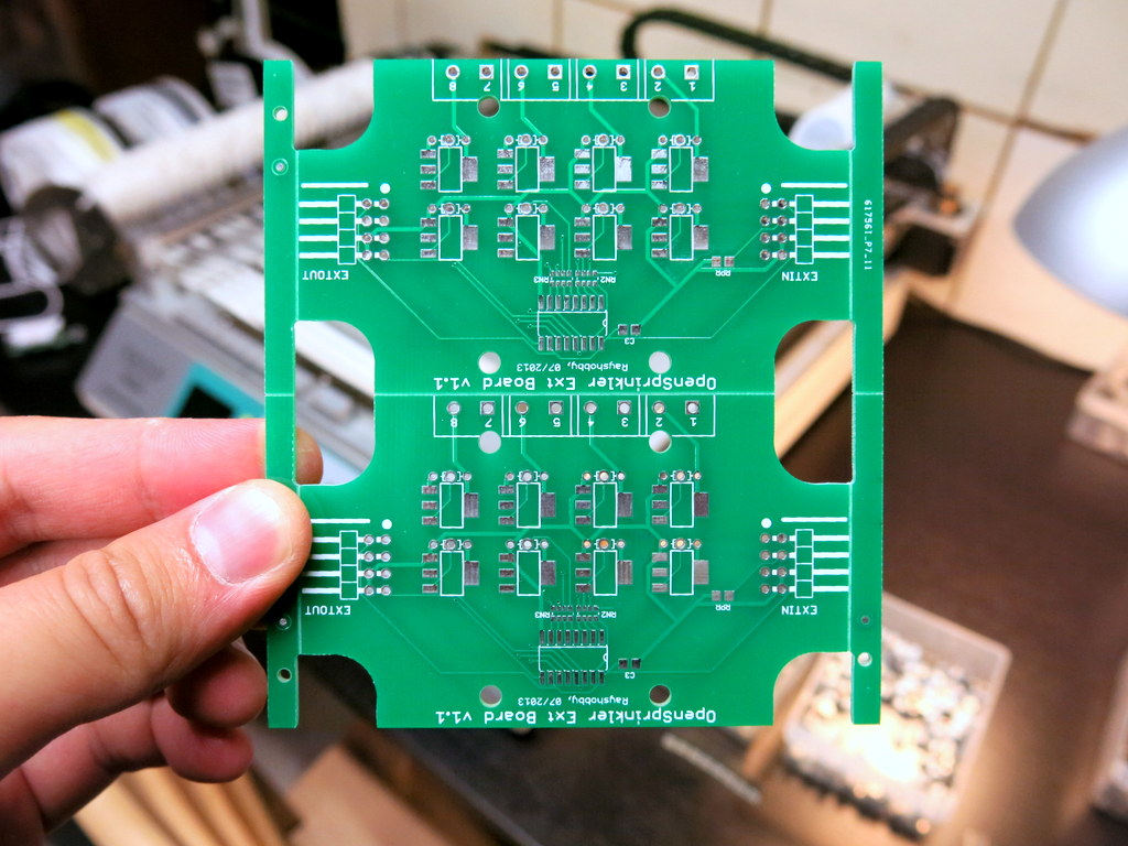
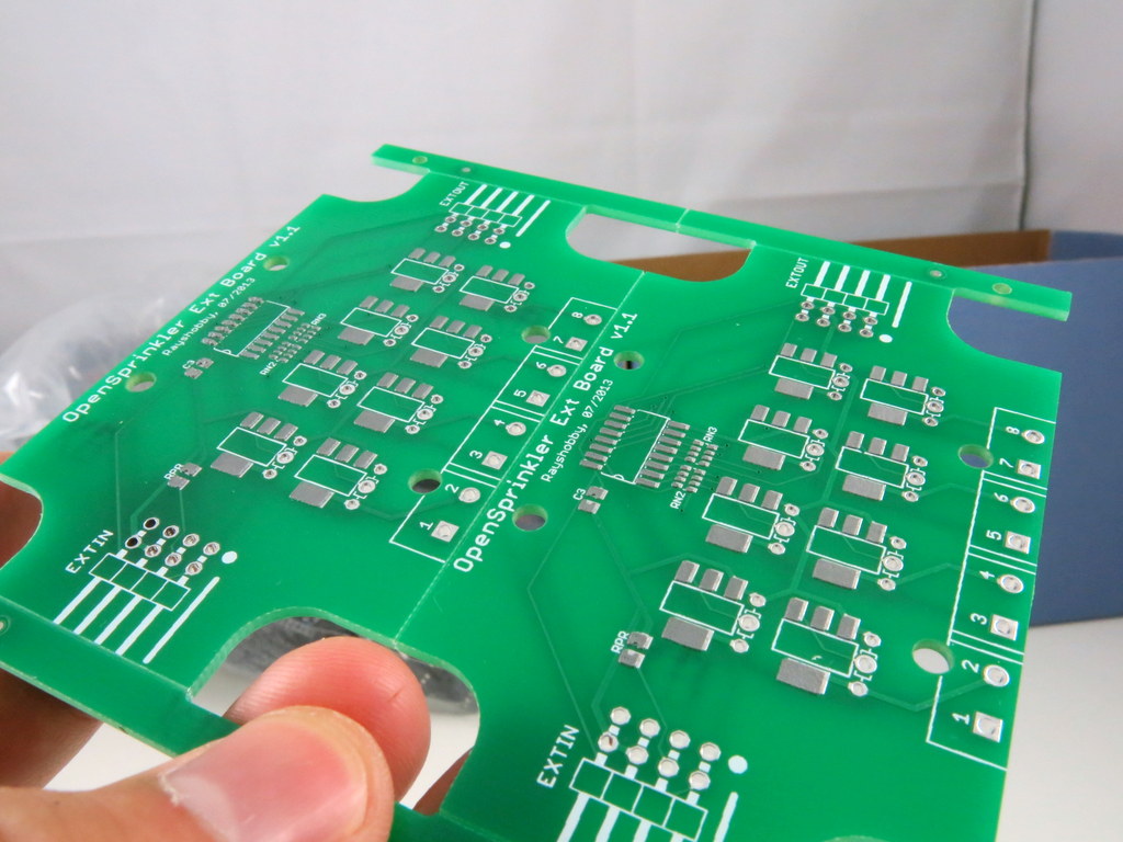
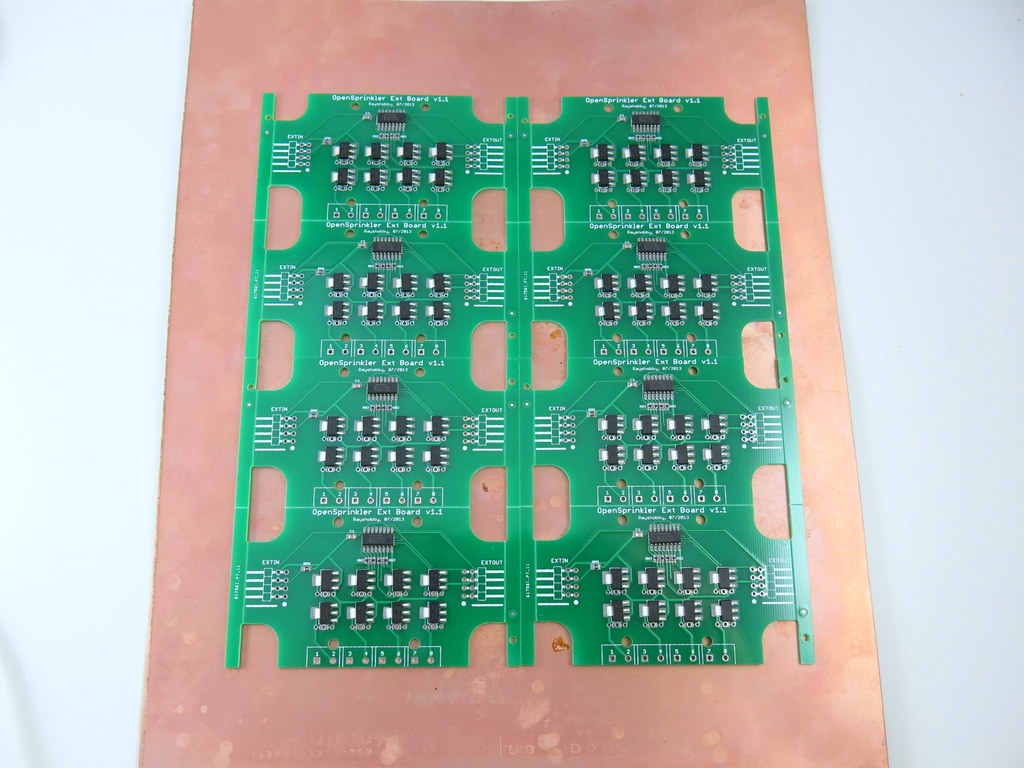
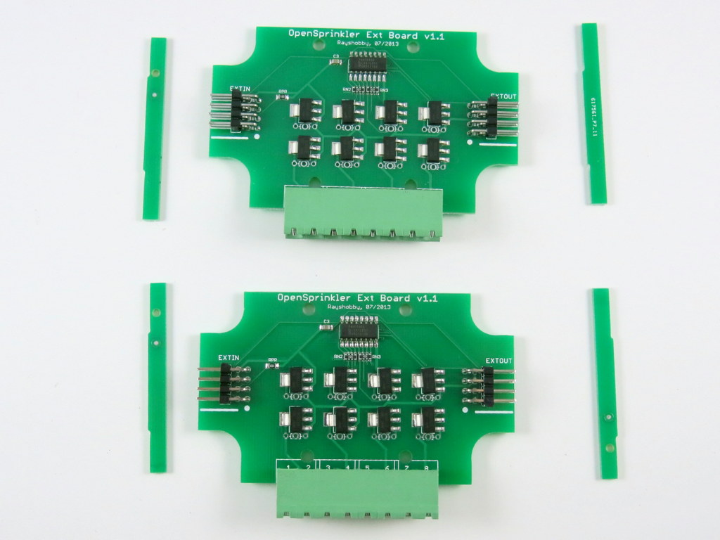
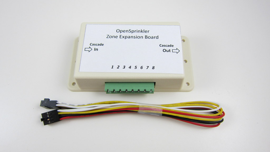
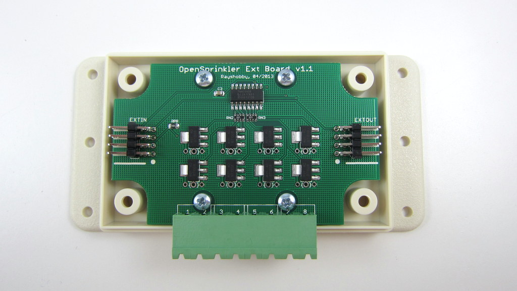
Previously, the zone expansion board is based on the same PCB as the main controller, and they share the same enclosure. This makes it easy to use a consistent enclosure design for both. However, the zone expansion circuit is actually very simple (just a shift register, a couple of resistors, and eight triacs), so it’s no need to commission a PCB as large as the main controller for something that can be much smaller. So I’ve decided to give the expansion board an upgrade, to version 1.1, which uses a much smaller PCB footprint, and its own dedicated enclosure (based on Serpac WM011).

IMG_3017IMG_3014

The new version is just a little over half the size of the original one. So in the same amount of space you can almost fit two expansion boards. This is particularly useful for people who has a limited space to fit a main controller and one or more expansion boards.

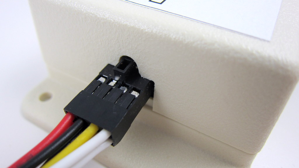
In addition, the zone expansion cable has been upgraded to use a polarized connector. Specifically, the connector has a small bump at the top, which matches the notch on the cutout of the enclosure. This way, there is only one possible orientation to insert the cable connector, thus preventing incorrect orientation:

IMG_3011IMG_3013

The picture on the left above shows the polarized cutout on the expansion board, and the picture on the right shows a similar cutout on the upcoming injection molded OpenSprinkler enclosure. This can help avoid mistakes when inserting the expansion cable. A special note that this cable has different pin connections with the previous version of expansion boards. So you should NEVER use the polarized cable with previous versions of zone expansion boards, or you may risk damaging your main controller!

Finally, expansion board v1.1 has added a 10K pull-down resistor, which when coupled with OpenSprinkler 2.0, allows the main controller to automatically detect the number of zone expansion boards. This feature is already included in hardware design, but hasn’t been implemented in software yet. The basic principle is that the main controller has a 1.5K pull-up resistor, and each expansion board has a 10K pull-down resistor. When multiple expansion boards are linked together, the pull-down resistors are connected in parallel, thus changing the divided voltage. By using an analog pin (which is internally wired to the voltage division point), the controller can easily calculate how many boards are linked together. A very simple solution!

To conclude, here is a short summary of the new features on OpenSprinkler Zone Expansion Board v1.1:

  • Reduced form factor, and dedicated enclosure.
  • Polarized expansion cable connector.
  • Added pull-down resistor for automatic detection of the number of expansion boards.
  • Besides, the new expansion board retains the on-board PCB holes to fit one MOV per zone, and it works with both OpenSprinkler and OpenSprinkler Pi.

That’s all for the update. This new version is in stock and available for purchase at Rayshobby Shop. Same old price!

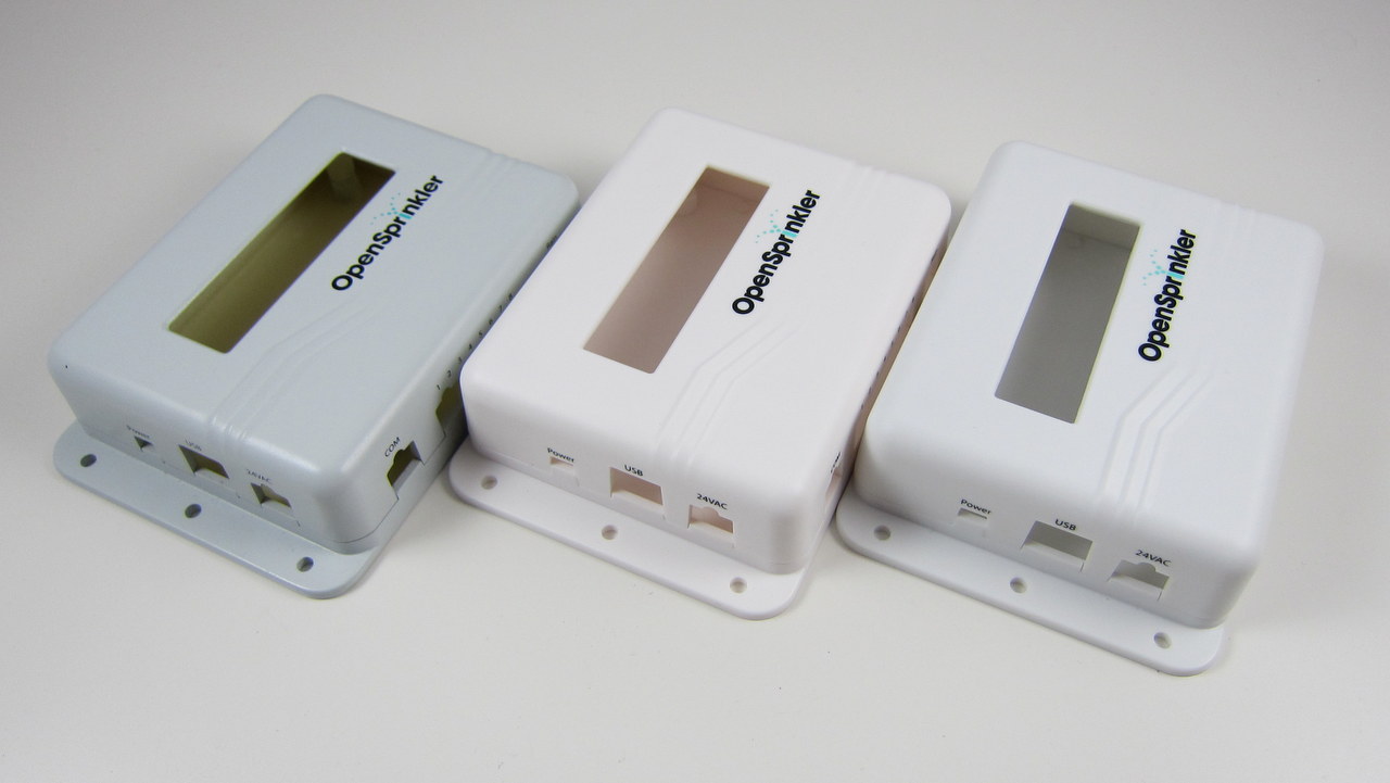
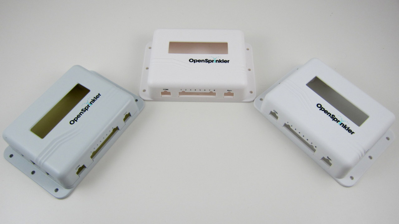
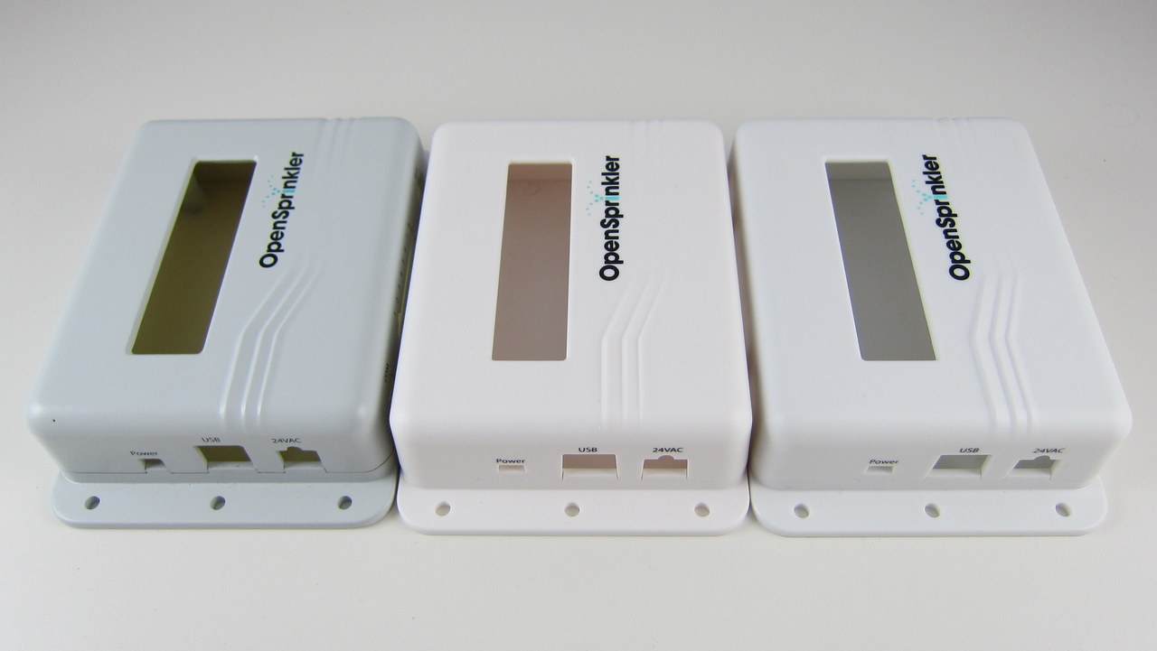
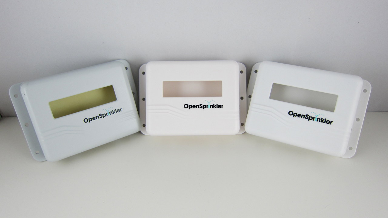
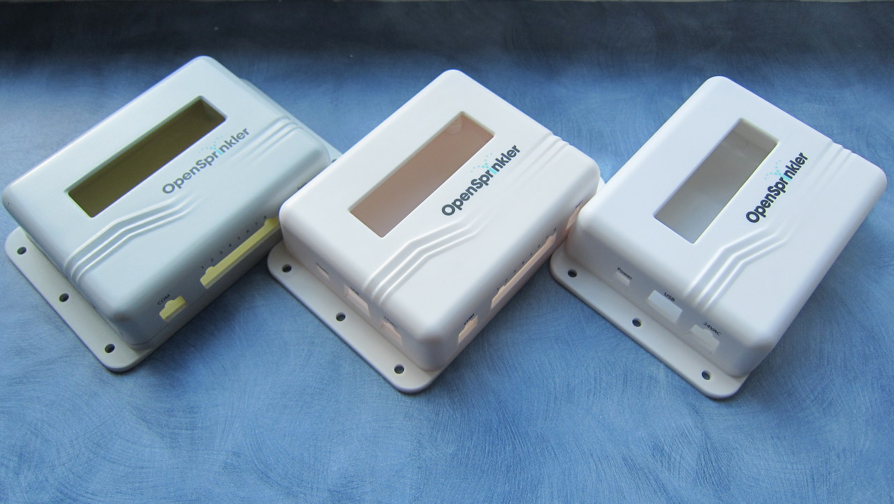
The final sample of the injection molded enclosure has arrived. Very exciting! The moment of decision: I’ve got three samples, each with a slightly different color. I’ve taken a few picture of all three side by side. The differences are subtle, but basically the first one (left) is more gray-ish, the second one (middle) is closer to milk white, the third one (right) is closer to pure white. Please vote for your favorite color in the comments section below (you can either use 1, 2, 3, or left, middle, right, or anything un-ambigious). I’ve only got a couple of days to give them my final decision, so please vote as quickly as you can. Thanks!

IMG_3003-001

IMG_3006-001

IMG_3005-001

IMG_3004-001

IMG_3000-001

After a few weeks of shipping these ‘underground’, I am finally happy to spread the words around: the OpenSprinkler Pre-Release v2.0s is officially available for sale! Note that this is the SMT assembled version — we don’t have DIY 2.0 yet. As usual, the first question to ask is what’s new in this version?

  • Upgraded MCU: OpenSprinkler 2.0 uses ATmega644, which is twice as much as ATmega328 in all aspects (i.e. flash memory size, GPIO pins, RAM, EEPROM, perhaps price as well 🙂 ). This makes it possible to add new features that I have planned ahead (e.g. weather-based control, logging, interfacing with wireless devices etc.) We will no longer be constrained by the flash memory size, well, at least for a while.
  • Upgraded Switching Regulator: the switching regulator (for 24VAC->5VDC conversion) has been upgraded from MC34063 to LM2596, which is less noisy and capable of outputting higher current. As more users are powering WiFi adapters through OpenSprinkler’s USB port, it’s important to make the power conversion section robust. The same circuitry is now also used in OpenSprinkler Pi. Details about this change can be found in this blog post.
  • Added microSD Card Slot: microSD card is useful for expanding the storage size of a microcontroller. This s great for a lot of purposes, such as logging, storing a lot of sprinkler programs, Javascript files etc. A standard microSD card shares the SPI interface and requires only one extra GPIO pin to operate. Hence adding microSD card support is a no brainer!
  • Expansion Board Detection: this allows the main controller to automatically detect the number of zone expansion boards linked to the controller. Not so crucial, but neat. The implementation is actually quite simple: it uses a pull-up resistor on the main controller and one pull-down resistor on each expansion board to form a voltage divider. By checking the voltage using an analog pin, the mcu can easily calculate how many boards are linked.
  • Other Features: given the plentiful GPIO pins available on ATmega644, I’ve added support to adjust LCD contrast and backlight (using two PWM pins), a set of pin headers for plugging in an off-the-shelf RF transmitter (for interfacing with wireless devices). The other un-used pins are made available in the pinout area (including three analog pins, two interrupt pins, two digital pins, as well as TXD, RXD, SDA and SCL).

OK, that’s quite a detailed list of new features. Here is an annotated diagram of the actual hardware:

os20_component_diagram

Also, just for fun, a diagram that shows each module of the circuit and where they are located on the PCB:

os20_module_diagram

The reason I call this the Pre-Release 2.0 is that the official 2.0 will use the injection molded enclosures I blogged about in this post. While that is already in production at SeeedStudio, I can’t give a reliable estimate of how long it will take for the final products to arrive. There have already been multiple delays, so I won’t be surprised if there are more… Other than the difference in the enclosure design, the pre-release 2.0 hardware is the same as the final 2.0.

If you are wondering what I mean by ‘shipping these underground’ at the beginning of the post — we’ve been automatically upgrading the recent orders of assembled OpenSprinkler v1.4s to v2.0s. Why not make it public? Well, there are several reasons. The first is that due to the Maker Faire and the vacation after that, I haven’t had time to finish the documentations, and I’m reluctant to officially release a product when the documentations are not ready yet. Second, I’ve been experimenting with minor changes of the 2.0 design, and we’ve been shipping several small batches, each with slight different hardware design. This is an important process to get user feedback, and to iron out all engineering issues before the official release. Finally, as many users have been waiting for 2.0, I don’t want to suddenly get into an overload situation, where the number of orders exceed our capacity to process them.

In terms of software, OpenSprinkler 2.0 is currently flashed with firmware 2.0.0, which is functionally the same as firmware 1.8.3, except for the additional options such as LCD contrast and backlight, and the support for a higher number of expansion boards and programs. More exciting firmware features will be gradually added over time. Also, starting from firmware 2.0.0, the source code can be compiled in Arduino 1.x (latest stable version is 1.0.5), and this is also the recommended Arduino version to compile OpenSprinkler code. I will continue to provide a VirtualBox image which has everything needed for compilation set up and ready to go.

The final bit of news: if you are interested in DIY 2.0, unfortunately that won’t be available for at least a couple of months. The delay is partly because the new injection molded enclosures are not ready yet (there is no space in the current enclosure to fit all through-hole components), and partly because there are a few design decisions I haven’t ironed out yet. So at least for a couple of months we will keep offering DIY 1.42u for anyone who wants to build OpenSprinkler from scratch.

So much for the announcement of OpenSprinkler Pre-Release 2.0. Feel free to leave your comments and suggestions below, or at the Rayshobby Forum. Thanks!

« Newer Posts - Older Posts »