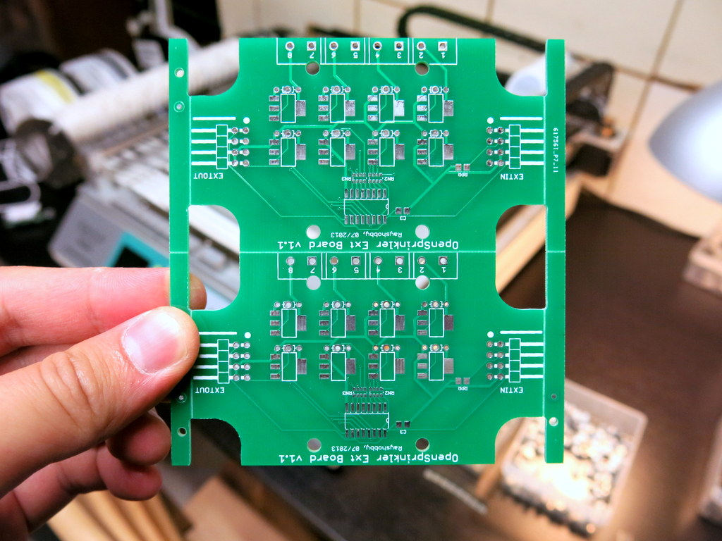
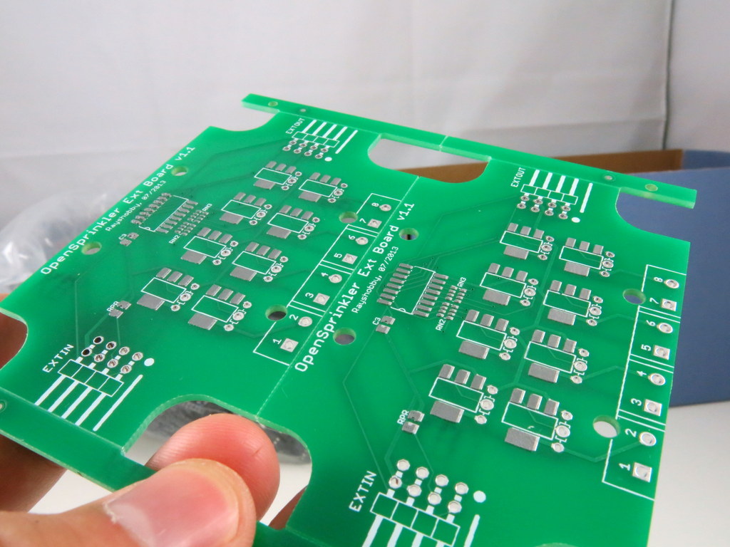
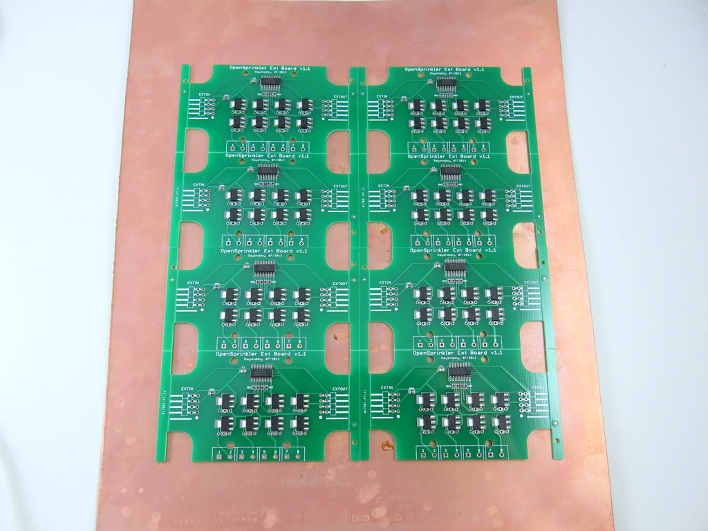
A lot of prototype PCBs arrived over the weekend. Among them is my long-waited OpenSprinkler Beagle — a sprinkler / irrigation extension board for the BeagleBone Black. Cool, time for some prototyping actions!
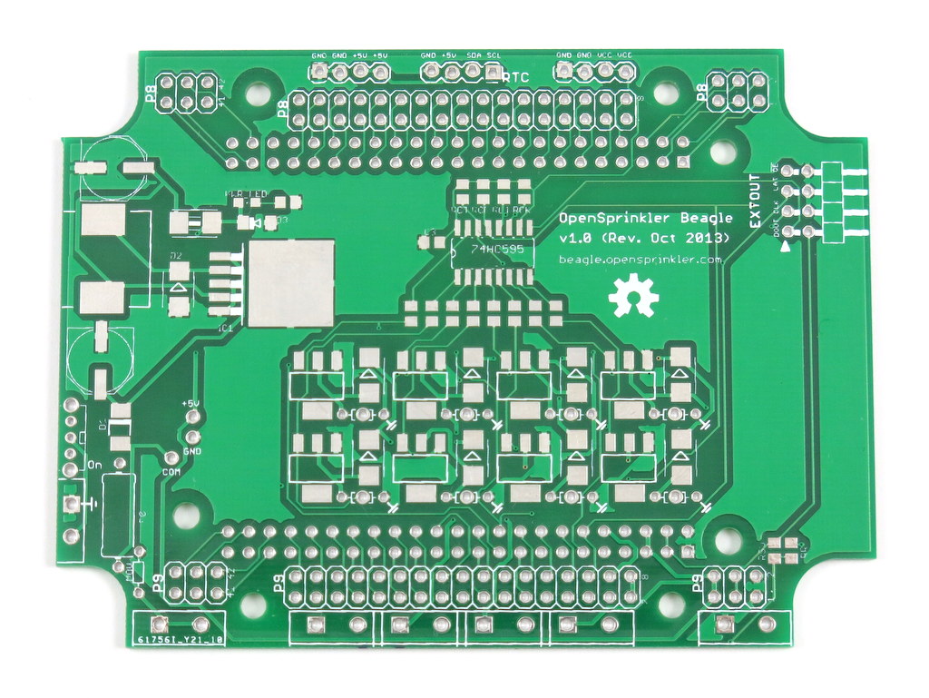

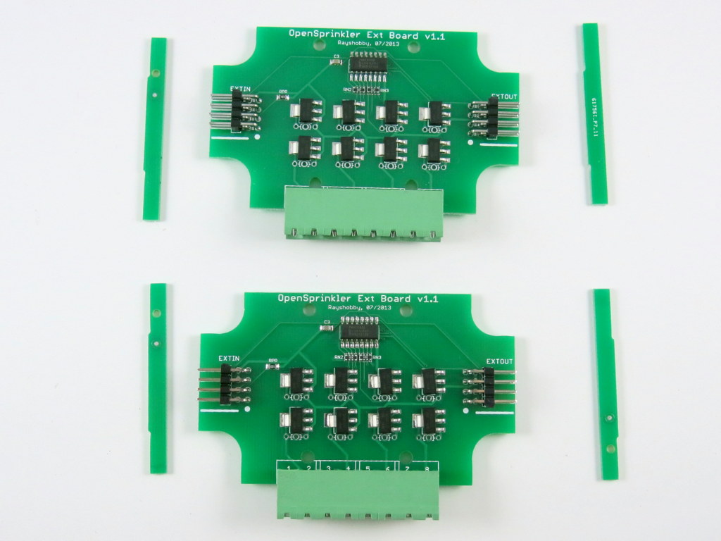
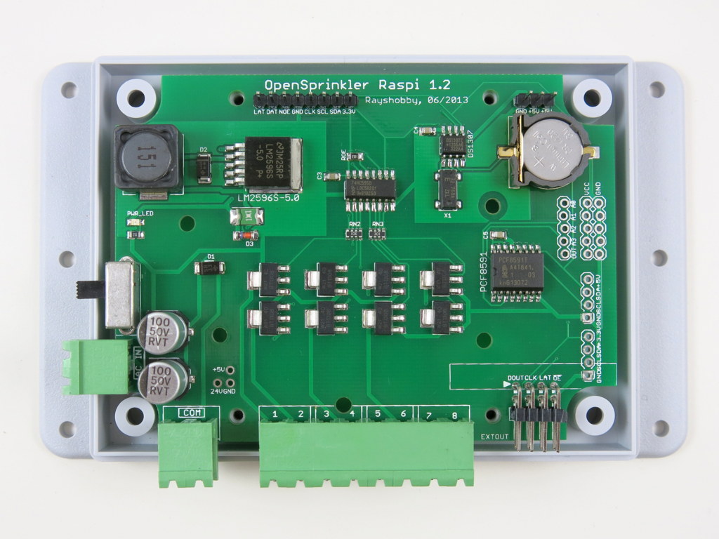
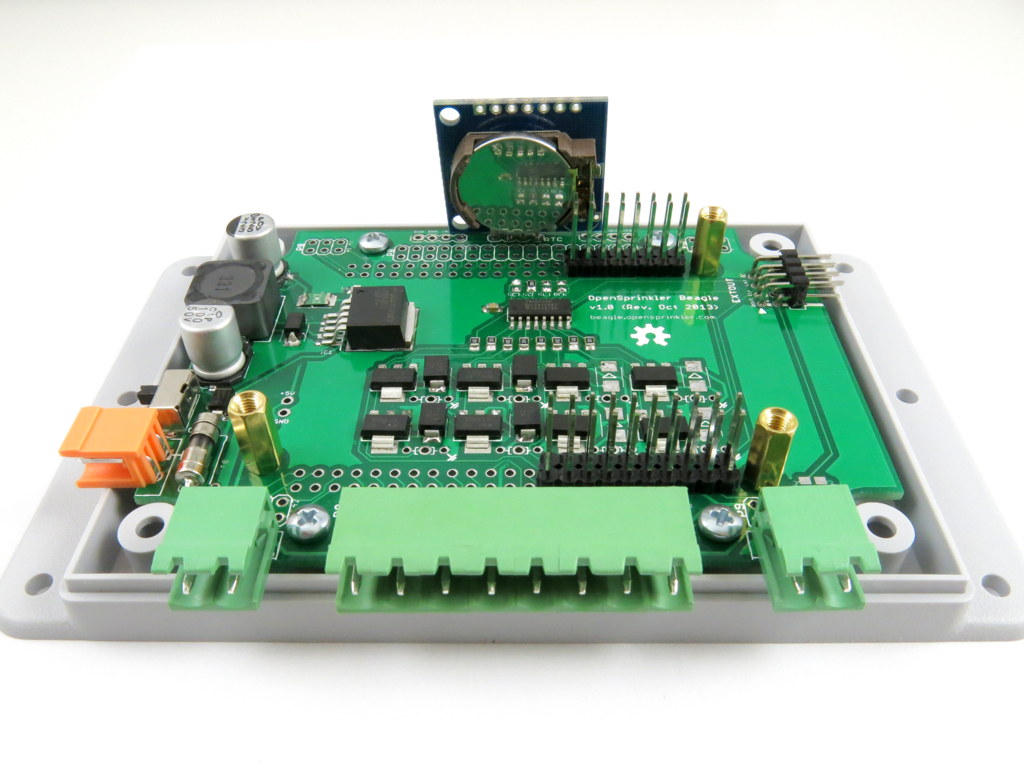
The design of OpenSprinkler Beagle largely follows OpenSprinkler Pi (OSPi). As usual, the board contains a 24VAC to 5VDC switching regulator, shift register, triacs, terminal blocks, and zone expansion board connector. It provides 5V power to the BeagleBone Black, uses 4 GPIO pins (specifically P9_11, 12, 13, 14) to interface with the shift register, and SDA2/SCL2 to interface with the DS1307 RTC. Since the BeagleBone and RPi are similar in size, I can reuse the same enclosure as I’ve been using so far.
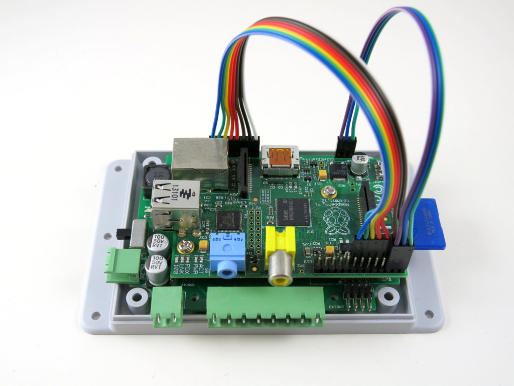
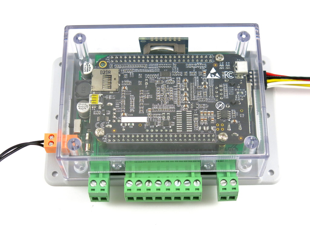
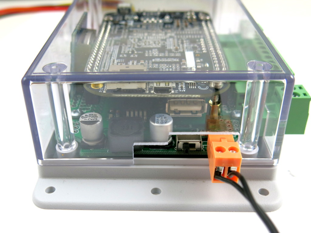
There are also several changes and improvements. First and probably the biggest design change is that the BeagleBone Black is now oriented face-down, and it plugs directly to the extra long male pin headers as you can see on the pictures above and below. In contrast, on OSPi, the Raspberry Pi is oriented face-up, and connection from RPi to the board is through a pair of 8-pin and 3-pin cables. The biggest advantage of the face-down design is that it saves the cables, and there is now some extra space in the upper-half of the enclosure, making it possible to add additional modules. To make it easy to reuse the available pins on the BeagleBone, I’ve also mapped out all the 46 pins on ports P8 and P9 to the pinout area.
I actually wanted to use the same design for OSPi, but it’s more tricky because RPi uses male pin headers, which means the extension board will have to provide female pin headers. I haven’t been successful at finding extra long female pin headers, but I will keep looking.

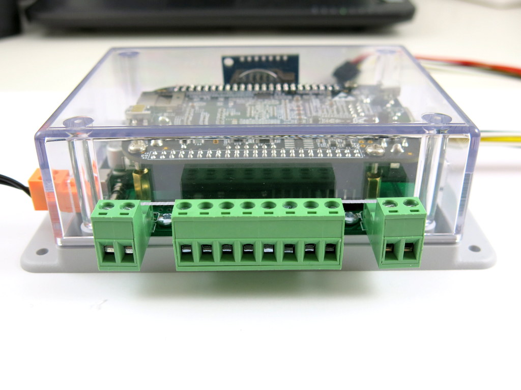
Among the other changes: the 24VAC port is now using a new type of terminal block that has different pin spacing and color with the others. This will reduce the chance of accidentally plugging 24VAC into the COM or rain sensor port, which has happened before. Speaking of rain sensor port, yes, there is now a rain sensor terminal — it takes one extra GPIO pin, but there are plenty of GPIO pins on the BeagleBone, so who cares 🙂
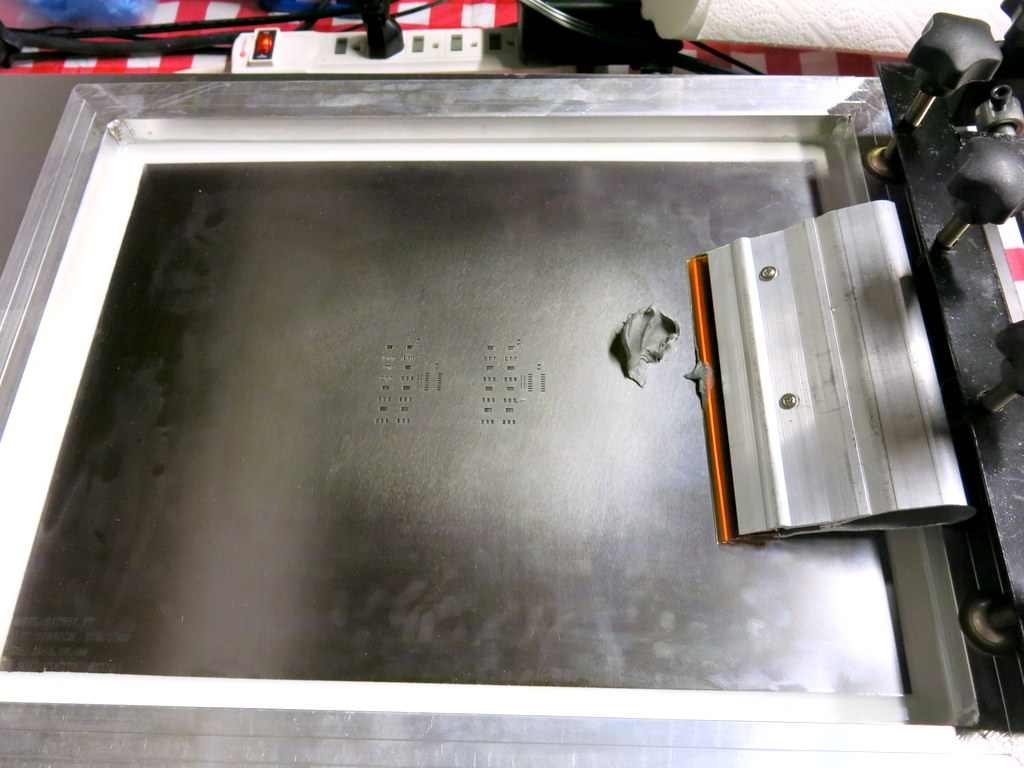
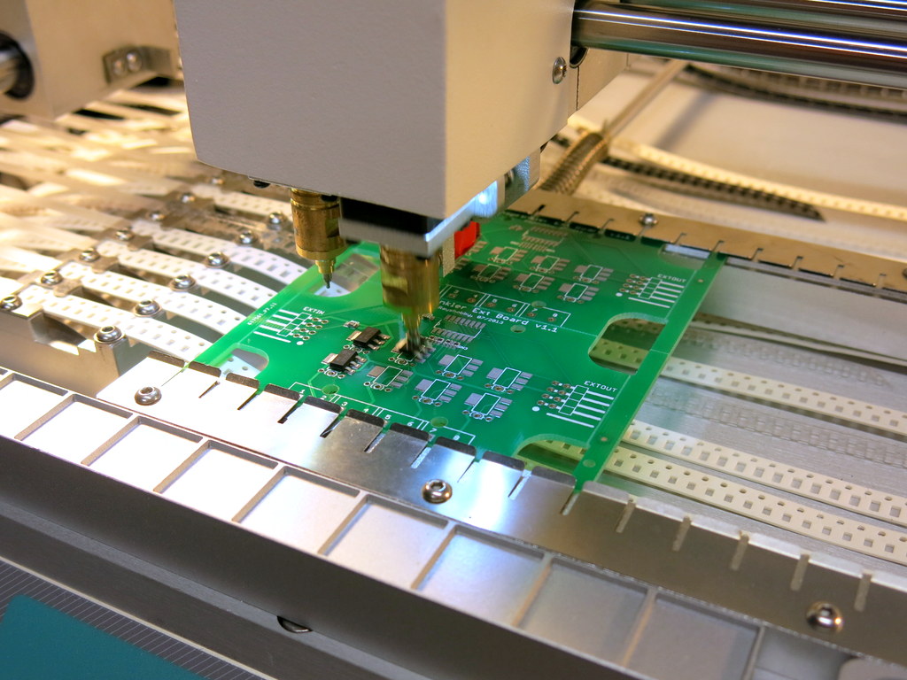
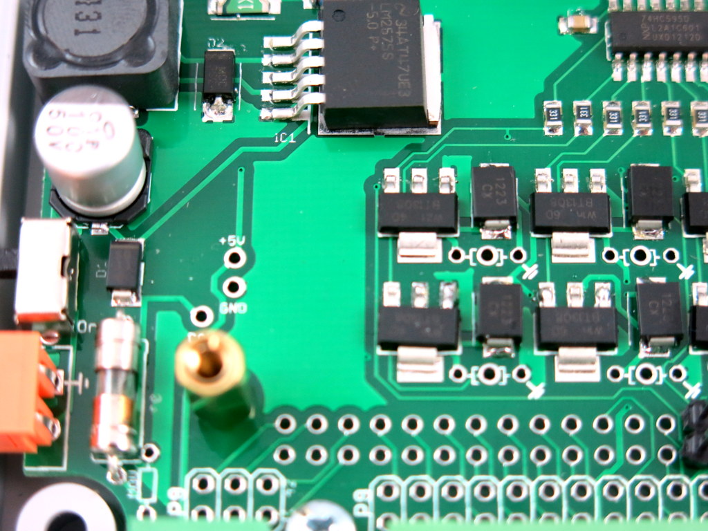
Also, I’ve added a 2A fuse, and nine 48V bidirectional TVS (transient-voltage suppressor) — one for the power in, and one for each of the eight zones. This will provide some level of protection to the circuit during power surges and lightening. In the past I’ve used MOVs (metal-oxide varistors). Those are pretty cheap, but they are bulky and have to be hand-soldered since they are through-hole components. TVS is a bit more expensive but can be easily automated using pick-and-place machines.
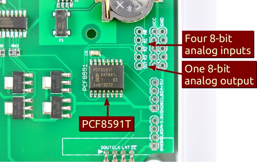
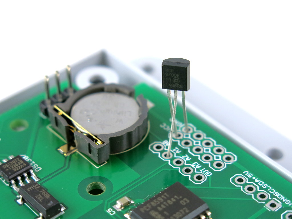
Also, the analog-digital converter (ADC) has been removed since the BeagleBone has built-in analog pins. As sort of an experiment, I also removed the on-board DS1307 RTC, but instead added pin headers to plug in an external RTC module, as you can see close to the top of the PCB. This was done as an experiment to empty out some space on the PCB to allow future expansion. But it turns out to be not very successful, because the module actually takes quite some space and makes it difficult to close the top cover.
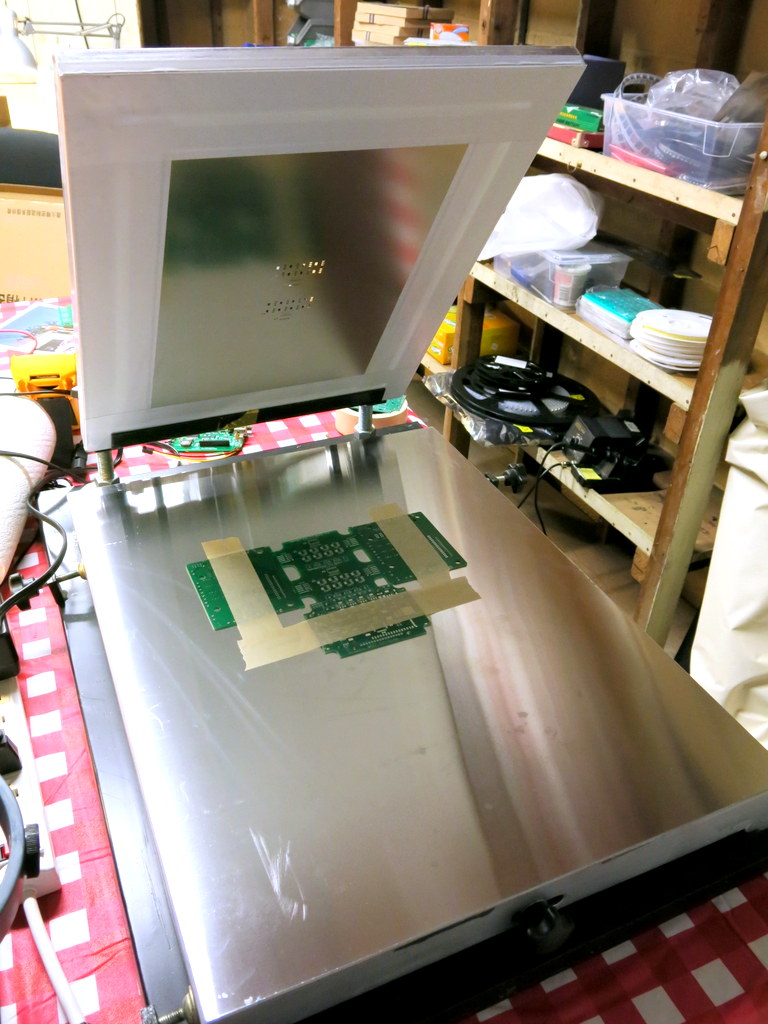
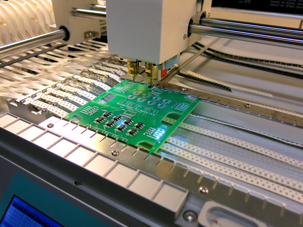
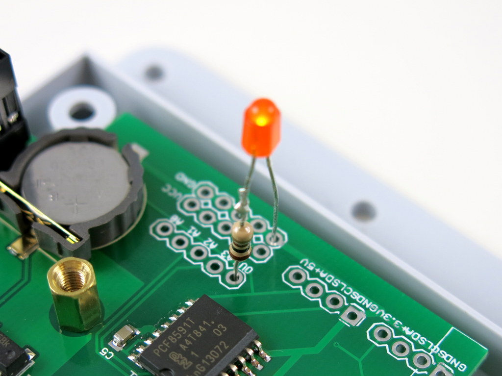
Here are some additional pictures of the assembly:
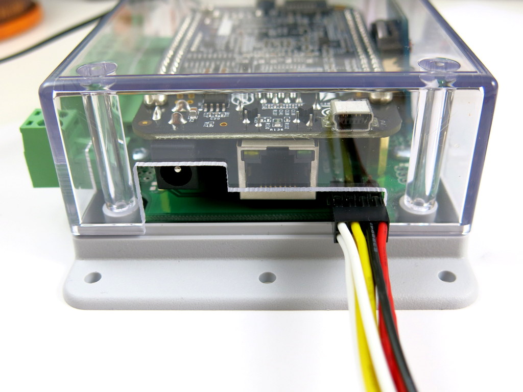
I quite like the overall design. There are a few minor changes I want to make before the official release. For example, the 100uF capacitor is currently too close to the BeagleBone’s USB port, and it needs to be moved further away. Also, I can make the PCB color black to match the color of the BeagleBone Black. By the way, I learned from the forum that some users want to use the sprinkler controller to control garage doors. I figured it’s it’s pretty easy to add a relay on the board for general-purpose applications. So I am gonna try to add that too.
Naming
What would be a good abbreviated name for OpenSprinkler Beagle? Since it’s designed for the BeagleBone Black, I could call it OSBBB, but I want to distinguish it from another product I am working on — the OpenSprinkler Bee (OSBee). OSBBB and OSBee are too close with each other to pronounce. One possibility is to call it OS-Bo, which would put it nicely in a series with OS-Pi and OS-Bee. If you have better suggestions, feel free to leave a comment below. Thanks!