OpenSprinkler Extension Board Build Instructions
(Note: all images below are clickable, in order for you to see the full-resolution details.)
Versions
Version 1.3u/v1.4 Extension Board
 |
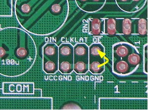
The OpenSprinkler extension board uses the same PCB as the main controller, but with only a subset of components. Specifically, these are shift register (74HC595), two 330ohm resistor arrays, eight triacs, one 8-port screw terminal, and two 2×4 pin headers. A 2×4 extension cable is also included. The extension board PCB is marked by a purple label. The soldering instructions are similar to Part 3 of the controller assembly instructions. |
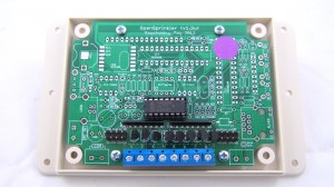 |
Solder the components to the PCB. Refer to the picture on the left. |
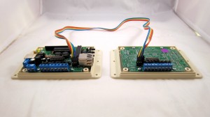 |
Take out the extension cable, plug one end to the main controller’s EXTOUT (right) connector, and the other to the extension board’s EXTIN (left) connector. The cable is symmetric, so it doesn’t matter which end goes to the main controller, as long as you both ends are plugged in the same orientation. In other words, make sure the wire colors are ordered in the same way. The diagram below shows the actual pin connections.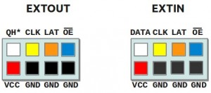 If you have multiple extension boards, you can cascade them in the same way: connect the EXTOUT of the previous board to the EXTIN of the next board. |
Version 1.2u Extension Board
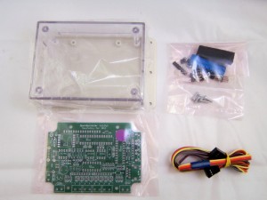 |
The OpenSprinkler extension board uses the same PCB as the main controller, but with only a subset of components. Specifically, these are shift register (74HC595), 10K resistor, two 330ohm resistor arrays, eight triacs, one 8-port screw terminal, and two 2×3 pin headers. A 2×3 extension cable is also included. The extension board PCB is marked by a purple label. The soldering instructions are similar to Part 3 of the controller assembly instructions. Note: IC socket is not included for the shift register. Please solder the shift register directly to the PCB. |
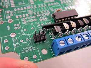 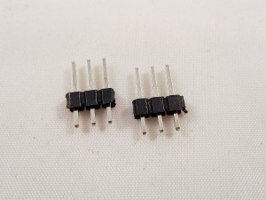 |
Solder the components to the PCB. Refer to the picture on the left. The 10K resistor goes to R1. Most kits should have two 2×3 male headers. Solder one of them to EXTIN (left) connector pinout, and the other to the previous board’s EXTOUT pinout. To cascade multiple extension boards, simply connect the previous board’s EXTOUT to the next board’s EXTIN. Some kits may have two 1×8 male headers. In this case, use a diagonal cutter to cut out two 1×3 male headers, and solder them individually to the pinouts to make a 2×3 pin header. |
 |
Take out the extension cable, plug one end to the main controller’s EXTOUT (right) connector, and the other to the extension board’s EXTIN (left) connector. The cable is symmetric, so it doesn’t matter which end goes to the main controller, as long as you both ends are plugged in the same way (i.e. the same orientation). Each end is actually a 2×4 connector, with two empty holes. The diagram below shows how the pin connections.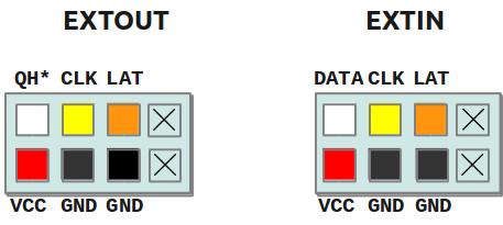
|
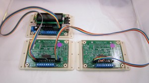 |
If you have multiple extension boards, cascade them in the same way. The picture on the left shows an example. The pictures below show two close-up views.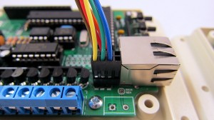 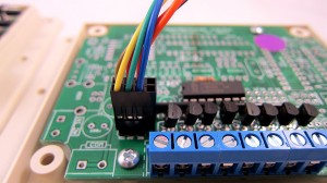
|
Version 1.1 Extension Board
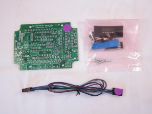 |
The OpenSprinkler extension board uses the same PCB as the main controller, but with only a subset of components. Specifically, these are shift register (74HC595), 10K resistor, two 330ohm resistor arrays, eight triacs, one 8-port screw terminal, and two 2×3 pin header. A 2×3 extension cable is also included. The extension board PCB is marked by a purple label, which matches one end of the extension cable. The soldering instructions are similar to Part 3 of OpenSprinkler assembly instructions. Note: IC socket is not included for the shift register. Please solder the shift register directly to the PCB. |
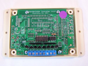 |
Insert the components to the PCB and solder them. This is pretty straightforward, except for two notes:
1. The pin headers are 4+2 pins. Insert it such that 4 pins are on the top (DATA, CLK, LAT, QH*), and 2 pins are on the bottom (VCC, GND). Leave the 24V pins open and do not use them. If the pin headers are too long, clip them with a diagonal cutter. 2. Depending on the PCB you’ve received, the 10K resistor may located differently than shown.
This resistor is not crucial, so it’s ok if you leave it out. |
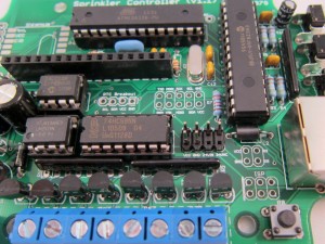 |
If your main (master) controller does not already have the 4+2 pin header, solder it now. Again, make sure that you leave the two 24VAC pins open and do not use them. |
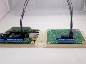 |
Take out the extension cable. Plug the end with a purple label to the extension board, and the other end to the master controller. The cable has 3+2 wires. Make sure the bottom 2 wires go into the VCC and GND pins.
Basically, the cable should make the following connections (master->extension board): |
Here are two close-up views of the connectors. Note that the wire colors may differ from the cable you received.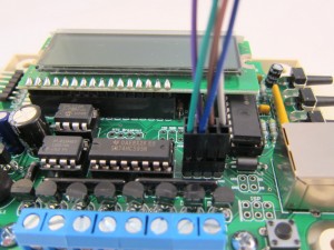 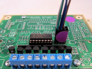
|
