
OpenSprinkler F.A.Q.
- Circuit Design and Extensions
- Modify the Code
- Modifications and General Use
- Sprinkler Valves
- Networking Issues
Circuit Design and Extensions
Q: What pins are available for connecting to external sensors and/or circuits?
A: The available pins depend on the particular hardware version. Please check the PCB image of each version, and the available pins are all marked in the pinout area. Here is a short summary:
- Hardware v1.0: TXD, RXD, (SPI) SCK, MOSI, MISO, (I2C) SDA, SCL, digital D3.
- Hardware v1.1: TXD, RXD, (SPI) SCK, MOSI, MISO, (I2C) SDA, SCL, digital D3 and D9.
- Hardware v1.2u: (I2C) SDA, SCL, digital D2, D3, analog A1.
- Hardware v1.3u: (I2C) SDA, SCL, analog A1, A2, A3.
- Hardware v1.4u/1.42u: (I2C) SDA, SCL, analog A2, A3.
- Hardware v1.4s: (I2C) SDA, SCL, analog A2, A3, A6, A7.
- Hardware v2.0s: (I2C) SDA, SCL, analog A5, A6, A7, serial TXD, RXD, interrupts INT0, INT2, digital D14, D15.
Note that Arduino analog pins can also be used as digital pins. Also, if not using the RFM12B transceiver, digital pins D2 and D10 are free in all hardware versions.
Q: Can I power a USB WiFi adapter (or other USB devices) through OpenSprinkler?
A: This is supported by default from hardware versions 1.42u and 2.0s. For earlier hardware versions, please check this blog post.
Q: How to add MOVs (varistors)?
A: From OpenSprinkler 2.1, the fully assembled OpenSprinkler has built-in bidirectional transient voltage suppressor (TVS). There is no need to install MOVs for fully assembled OpenSprinkler (2.1 or above).
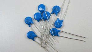
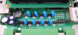
MOVs are useful for protecting the controller from impulse high voltages such as lightning. The surface mount versions (including 1.4s, 2.0s, and zone expansion boards) currently have PCB holes designed to fit one MOV per station. You can solder MOVs by following the picture below: each MOV (blue colored) should be inserted across the top and bottom holes next to every triac. The stock MOVs that we offer are of type 07D560K.
Q: How to use OpenSprinkler to interface with DC devices?
A: There are two solutions. The simplest is probably to use a relay board, which you can get from Amazon, eBay and a variety of places. The basic idea is that OpenSprinkler will control the relays, which in turn control DC devices. See the blog post here for an example.
A potentially simpler and cheaper option is to use OpenSprinkler to directly drive DC devices. This can be done by replacing the traics (i.e. AC transistors) with DC transistors. We recommend MPSA14, a common NPN Darlington transistor. However, note that if the DC devices you are driving are inductive load (such as DC valves), you need to solder additional protecting (flyback) diodes, one per station. The positive lead of the diode should go to the common wire, and the negative lead should go to each individual station wire.
Q: How to add an external Real-Time Clock (RTC) module?
A: RTC (DS1307) support has been added in code since firmware 1.7. RTC allows time keeping even when the controller is offline. OpenSprinkler hardware 1.4 or above has built-in RTC and backup battery, and the RTC option is turned on by default. For previous versions of OpenSprinkler hardware, you can add an external RTC module by connecting the following pins (from RTC module to controller): SDA->SDA, SCL->SCL, VCC->VIN(+5V), GND->GND. Note that you must use the VIN(+5V) line on the controller: the VCC line on the controller is +3.3V and will not work for the DS1307 RTC. Special notes:
- On v1.0, there is no pinout for VIN. Please check the schematic to identify pads that are connected to the VIN line.
- On v1.1, there is an RTC breakout pin header. Do not use this pin header because there is an error in its design. Instead, use the pins in the main pinout area.
- On v1.2u, the VIN pin is located on the upper-left corner of the PCB, next to the indicator LED.
The external DS1307 RTC module is available from Rayshobby Shop. It is also available at Adafruit and Sparkfun.
Q: Why is there not a built-in WiFi chip on the controller?
A: As I explained in this page, this is mainly due to the cost of adding a WiFi chip and the lack of robust open-source WiFi solutions currently. However, you can provide the controller with wireless connectivity by using WiFi repeater or bridge. This way, the WiFi password and security options will be handled by the repeater or bridge, so the controller does not have to deal with them at all. This makes a lot of sense because WiFi repeaters are inexpensive (the cheapest options are $20-$30), and it significantly reduces the code on the controller side, thus improving it robustness.
More circuit design notes can be found in this blog post.
Modify the code
Q: How do I know which file to modify?
A: The OpenSprinkler code consists of two components: an OpenSprinkler library, which provides functions to interface with the hardware (e.g. solenoid Ethernet, LCD controls etc.), and a scheduling program, which implements a scheduling algorithm and maintains schedule data. In most cases, you will probably be modifying the latter. The scheduling program is further divided into a main program (e.g. interval_program.pde), a server program (server.pde), and program data structure (e.g. program.h/.cpp). The main program is in charge of initialization, setting up controllers, and running the main loop; the server program responds to Ethernet packets, and the program data structure keeps the necessary program data.
Q: How do I implement a new http GET command?
A: The basic steps are:
- Go to server.pde, find the analyze_get_url function, and add a new GET keyword there (e.g. getstatus)
- Implement a function that responds to the keyword (e.g. print_webpage_getstatus)
- Inside print_webpage_getstatus function, parse the input http string to extract the information you need (e.g. station index, custom requests), and then call suitable functions to instrument these requests
- Return an http page by calling bfill.emit_p and insert strings and/or data. Example return pages are a simple http webpage that prints the data requested, a confirmation page, an automatic re-direct, or a Unauthorized page in case something is wrong with the incoming requests.
Q: How do I change the http port number?
A: From firmware v1.8, http port can be set on the Options webpage.
Modifications and General Use
Q: What’s the range of allowed input power voltage?
A: The absolute maximum input voltage is 28V if using AC, or 40V if using DC (note that the peak voltage of 28VAC is about 40V). This is mainly limited by the voltage rating of the switching regulator, which can handle up to 40V input. The minimum input voltage is 6V, as the switching regulator is set up in ‘step-down’ mode and diode D1 will drop about 0.7V.
When you measure the open-circuit voltage of your sprinkler transformer, sometimes you will get a reading higher than 28VAC. This is ok. These transformers are not regulated, so the open-circuit (i.e. no load) voltage can be quite high. Once you connect the transformer to a circuit and current is drawn from it (i.e. with load), the voltage will drop to about 24~25VAC.
Q: I understand the main controller can control up to 8 station. How to expand beyond 8 stations?
A: From OpenSprinkler v1.1, zone expansion is generically supported in both hardware and software. This is implemented by adding pinouts for the 74HC595 shift register. A connector is used to link master controller with zone expansion boards, each of which extends the number of stations by 8. The connection follows (master->expansion): CLK->CLK, LATCH->LATCH, DOUT (QH*)->DIN (DATA), VCC->VCC, GND->GND. Check the Zone Expansion Boards page for additional details.
Q: How do I perform an emergency stop?
A: You can stop the operation of the controller either by clicking the ‘Stop Operation’ button (requires password) on the homepage, or by pressing and holding button B2 on the controller manually.
Q: I replaced the mcu with a fresh one I bought from Digikey. Now I get an avrdude: initialization failed, rc=-1 error. What should I do?
A: To use a fresh mcu, run the following command first:
avrdude -c usbtiny -p m328p -B 250 -F -U lfuse:w:0xe2:m -U hfuse:w:0xd1:m -U efuse:w:0x06:m
This will set the correct fuse bits, and then you can upload a program. More technically: the USBtiny programmer that comes with OpenSprinkler is set to work at the highest speed by default. This requires the ATmega328 to run at 8MHz or above. Fresh mcus are usually clocked at 1MHz, so you need to set the fuse bits first to change the clock rate to 8MHz.
Sprinkler Valves
Q: What’s the maximum distance allowed between the controller and the valves?
A: This depends on the wire gauge (AWG) that you are using to connect the valves. Here is an example list of the maximum distance with respect to the wire gauge. In general, you should be able to run at least 700-800 feet (>200 m) by using 20 AWG wires, and longer if you use thicker wires.
Q: What’s the maximum distance allowed between the main controller and extension boards?
A: This depends on the wire gauge (AWG) of the extension board cable. The default cable shipped with the kit is a 15 inch long 24AWG cable. The resistance on each wire measures about 0.14 ohm. Since the control lines draw very little current, the voltage drop on the wire is usually very small. The ground line runs higher current as it sinks current for the sprinkler solenoids. Because of this, the circuit design allocates three wires to the ground to reduce resistance. Overall you can probably run at least 50 feet without significant voltage drop.
Q: Can I connect the sprinkler valves with garden hoses?
A: Yes you can. Most sprinkler valves use NPT (National Pipe Thread) standard, while garden hoses use GHT (Garden Hose Thread) standard. So you need an adapter. Just Google ‘NPT to GHT adapter’. You can also get these adapters in local retail stores such as Lowe’s or HomeDepot.
Q: My valves are making a loud noise and do not seem to be fully open.
A: You may have soldered RN1 (1K ohm resistor network) in the place or RN2 or RN3 (330 ohm resister networks). This would reduce the gate current of the triacs and thus they cannot remain fully open (saturated). Check to see if this is the case.
Networking Issues
Q: When using a WiFi adapter/bridge, the DHCP does not work – the controller cannot get a valid IP.
A: Try using static IP instead. To do so, hold B3 when powering up the controller, you will enter option setup mode. Click B3 to navigate to the ‘Use DHCP’ option, and set it to ‘No’. Following from this option, set static IP and gateway IP. Make sure these IP addresses are set correctly according to your router’s configuration.
Update: the latest firmware uses the new JeeLabs EtherCard library, which seems to have solved the DHCP issue. Flash your controller with the most recent firmware and see if it solve the problem.